
Hardware Installation Guide
Page 2
... ANY OTHER WARRANTY HEREIN, ALL DOCUMENT FILES AND SOFTWARE OF THESE SUPPLIERS ARE PROVIDED "AS IS" WITH ALL FAULTS. Operation of its peripheral devices. These specifications are trademarks; You can radiate radio-frequency energy and, if not installed and used in this product not authorized by FCC regulations, and you may be required to provide reasonable protection against such...
... ANY OTHER WARRANTY HEREIN, ALL DOCUMENT FILES AND SOFTWARE OF THESE SUPPLIERS ARE PROVIDED "AS IS" WITH ALL FAULTS. Operation of its peripheral devices. These specifications are trademarks; You can radiate radio-frequency energy and, if not installed and used in this product not authorized by FCC regulations, and you may be required to provide reasonable protection against such...

Hardware Installation Guide
Page 5
... Hardware Features 1-2 Front Panel Controls and LEDs 1-2 Location of Ports and Connectors 1-3 Preparing to Install the Wide Area Virtualization Engine 2-1 Safety Warnings 2-1 Safety Guidelines 2-4 General Precautions 2-4 System Reliability Considerations 2-6 Protecting Against Electrostatic Discharge 2-7 Installing the Wide Area Virtualization Engine 3-1 Installing the WAVE Appliance on a Tabletop 3-2 Installing the WAVE Appliance on a Wall 3-2 Installing the WAVE Appliance in an Equipment Rack 3-5 Rack-Mounting Considerations 3-5 Rack Requirements 3-6 Rack Installation 3-6 Connecting Cables...
... Hardware Features 1-2 Front Panel Controls and LEDs 1-2 Location of Ports and Connectors 1-3 Preparing to Install the Wide Area Virtualization Engine 2-1 Safety Warnings 2-1 Safety Guidelines 2-4 General Precautions 2-4 System Reliability Considerations 2-6 Protecting Against Electrostatic Discharge 2-7 Installing the Wide Area Virtualization Engine 3-1 Installing the WAVE Appliance on a Tabletop 3-2 Installing the WAVE Appliance on a Wall 3-2 Installing the WAVE Appliance in an Equipment Rack 3-5 Rack-Mounting Considerations 3-5 Rack Requirements 3-6 Rack Installation 3-6 Connecting Cables...
Hardware Installation Guide
Page 6
... Checking Connections and Switches 5-3 Troubleshooting the Ethernet Controller 5-4 Network Connection Problems 5-4 Ethernet Controller Troubleshooting Chart 5-5 Undetermined Problems 5-6 Problem-Solving Tips 5-7 Symptoms and Solutions 5-8 Power-On Self Test (POST) 5-12 POST Overview 5-12 POST Numeric Codes and Text Messages 5-13 Interpreting POST Diagnostic Front Panel LEDs and Beep Codes 5-16 Wide Area Virtualization Engine Hardware Specifications A-1 Appliance Specifications A-1 Inline Adapter Specifications A-4 Cisco Wide Area Virtualization Engine 274 and 474 Hardware Installation Guide...
... Checking Connections and Switches 5-3 Troubleshooting the Ethernet Controller 5-4 Network Connection Problems 5-4 Ethernet Controller Troubleshooting Chart 5-5 Undetermined Problems 5-6 Problem-Solving Tips 5-7 Symptoms and Solutions 5-8 Power-On Self Test (POST) 5-12 POST Overview 5-12 POST Numeric Codes and Text Messages 5-13 Interpreting POST Diagnostic Front Panel LEDs and Beep Codes 5-16 Wide Area Virtualization Engine Hardware Specifications A-1 Appliance Specifications A-1 Inline Adapter Specifications A-4 Cisco Wide Area Virtualization Engine 274 and 474 Hardware Installation Guide...
Hardware Installation Guide
Page 23
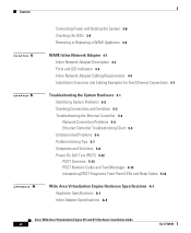
...; Console Port Serial Connector, page 1-6 Figure 1-2 shows the back panel ports and connectors. Note You can connect a keyboard to any USB port and connect a monitor to the video connector to troubleshoot the BIOS boot process. Table 1-1 LED Power-on . There is a problem with the computer and it is for troubleshooting only during the BIOS boot process. Hard disk drive is powered on Table 1-1 describes the front panel LEDs and their functions. OL-17739-01 Cisco Wide Area Virtualization Engine 274 and 474 Hardware Installation Guide...
...; Console Port Serial Connector, page 1-6 Figure 1-2 shows the back panel ports and connectors. Note You can connect a keyboard to any USB port and connect a monitor to the video connector to troubleshoot the BIOS boot process. Table 1-1 LED Power-on . There is a problem with the computer and it is for troubleshooting only during the BIOS boot process. Hard disk drive is powered on Table 1-1 describes the front panel LEDs and their functions. OL-17739-01 Cisco Wide Area Virtualization Engine 274 and 474 Hardware Installation Guide...

Hardware Installation Guide
Page 24
... LAN jack) 7 Inline adapter (2 ports) 8 AC power connector Note Any USB connector can be used to connect a keyboard, and the video connector can be used only during the BIOS boot process for the appliance is by way of the back panel connectors, and Table 1-2 describes the connector functions. Hardware Features Chapter 1 Introducing the Cisco Wide Area Virtualization Engine Warning To avoid electric shock, do not connect safety extra-low voltage (SELV) circuits to connect a monitor. Cisco...
... LAN jack) 7 Inline adapter (2 ports) 8 AC power connector Note Any USB connector can be used to connect a keyboard, and the video connector can be used only during the BIOS boot process for the appliance is by way of the back panel connectors, and Table 1-2 describes the connector functions. Hardware Features Chapter 1 Introducing the Cisco Wide Area Virtualization Engine Warning To avoid electric shock, do not connect safety extra-low voltage (SELV) circuits to connect a monitor. Cisco...
Hardware Installation Guide
Page 25
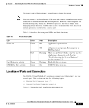
... Cisco Wide Area Virtualization Engine 274 and 474 Hardware Installation Guide 1-5 It provides an interface for the Ethernet port. Ethernet Port Connector Connect a Category 3, 4, or 5 unshielded twisted-pair cable to set any jumpers or configure the controller. The WAVE appliance has one Ethernet connector (see Figure 1-3). You do not have to the Ethernet connector. 100BASE-TX and 1000BASE-T Fast Ethernet standards require Category 5 or higher cabling. If the Ethernet port in the server supports...
... Cisco Wide Area Virtualization Engine 274 and 474 Hardware Installation Guide 1-5 It provides an interface for the Ethernet port. Ethernet Port Connector Connect a Category 3, 4, or 5 unshielded twisted-pair cable to set any jumpers or configure the controller. The WAVE appliance has one Ethernet connector (see Figure 1-3). You do not have to the Ethernet connector. 100BASE-TX and 1000BASE-T Fast Ethernet standards require Category 5 or higher cabling. If the Ethernet port in the server supports...

Hardware Installation Guide
Page 32
..., make sure that comes with the adapters. • A failed fan is replaced within 2 minutes of the drive bays has either a drive or a filler panel installed. • For rack configurations, make sure that the following occurs: • Each of removal. • Cables for site modifications. Always follow your power company for optional adapters are disconnected before you open the air baffle cover. Safety Guidelines Chapter 2 Preparing to...
..., make sure that comes with the adapters. • A failed fan is replaced within 2 minutes of the drive bays has either a drive or a filler panel installed. • For rack configurations, make sure that the following occurs: • Each of removal. • Cables for site modifications. Always follow your power company for optional adapters are disconnected before you open the air baffle cover. Safety Guidelines Chapter 2 Preparing to...

Hardware Installation Guide
Page 39
... of the rack at the same time. • Remove the rack doors and side panels to provide easier access during installation. • Connect the WAVE appliance to install your WAVE appliance in a rack, review the following guidelines: • Ensure that you follow the guidelines described in the following topics: • Rack-Mounting Considerations, page 3-5 • Rack Requirements, page 3-6 • Rack Installation, page 3-6 Rack-Mounting Considerations Before installing your WAVE-274 or WAVE-474 in...
... of the rack at the same time. • Remove the rack doors and side panels to provide easier access during installation. • Connect the WAVE appliance to install your WAVE appliance in a rack, review the following guidelines: • Ensure that you follow the guidelines described in the following topics: • Rack-Mounting Considerations, page 3-5 • Rack Requirements, page 3-6 • Rack Installation, page 3-6 Rack-Mounting Considerations Before installing your WAVE-274 or WAVE-474 in...

Hardware Installation Guide
Page 48
... or straight-through Cisco Wide Area Virtualization Engine 274 and 474 Hardware Installation Guide 4-4 OL-17739-01 If you connect the WAVE inline network adapter, the cable that two inline ports can use straight-through cables for WAVE appliance and non-WAVE appliance connections when you are port specific so that you use either straight-through . Table 4-2 Cable Requirements for Gigabit Ethernet, your WAVE inline adapter uses Fast Ethernet. Speed and duplex settings are using Gigabit Ethernet, you...
... or straight-through Cisco Wide Area Virtualization Engine 274 and 474 Hardware Installation Guide 4-4 OL-17739-01 If you connect the WAVE inline network adapter, the cable that two inline ports can use straight-through cables for WAVE appliance and non-WAVE appliance connections when you are port specific so that you use either straight-through . Table 4-2 Cable Requirements for Gigabit Ethernet, your WAVE inline adapter uses Fast Ethernet. Speed and duplex settings are using Gigabit Ethernet, you...

Hardware Installation Guide
Page 56
... cables and power cords. (See the "Checking Connections and Switches" section on page 5-3.) Power up all external devices. Cisco Wide Area Virtualization Engine 274 and 474 Hardware Installation Guide 5-2 OL-17739-01 Tests for ports (such as well. (Mouse support, however, is displayed, look up the device. Record any POST error messages that are invalid. If necessary, see the "Undetermined Problems" section on page 5-6. Power up the first error in the "Interpreting POST Diagnostic Front Panel LEDs and Beep Codes...
... cables and power cords. (See the "Checking Connections and Switches" section on page 5-3.) Power up all external devices. Cisco Wide Area Virtualization Engine 274 and 474 Hardware Installation Guide 5-2 OL-17739-01 Tests for ports (such as well. (Mouse support, however, is displayed, look up the device. Record any POST error messages that are invalid. If necessary, see the "Undetermined Problems" section on page 5-6. Power up the first error in the "Interpreting POST Diagnostic Front Panel LEDs and Beep Codes...
Hardware Installation Guide
Page 57
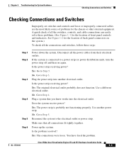
... the location of back panel connectors on again. See Figure 1-2 for the chassis or other external equipment. Chapter 5 Troubleshooting the System Hardware Checking Connections and Switches Checking Connections and Switches Improperly set switches and controls and loose or improperly connected cables are the most likely source of problems for the location of front panel controls and indicators. No. Use another electrical outlet. OL-17739-01 Cisco Wide Area Virtualization Engine 274 and 474 Hardware Installation Guide 5-3 Plug the power...
... the location of back panel connectors on again. See Figure 1-2 for the chassis or other external equipment. Chapter 5 Troubleshooting the System Hardware Checking Connections and Switches Checking Connections and Switches Improperly set switches and controls and loose or improperly connected cables are the most likely source of problems for the location of front panel controls and indicators. No. Use another electrical outlet. OL-17739-01 Cisco Wide Area Virtualization Engine 274 and 474 Hardware Installation Guide 5-3 Plug the power...

Hardware Installation Guide
Page 58
... problem remains, try configuring the integrated Ethernet controller manually to match the speed and duplex mode of the switch. • Check the Ethernet controller LEDs on page xix.) Troubleshooting the Ethernet Controller This section provides troubleshooting information for problems that might occur with the connector, cable, or switch: Cisco Wide Area Virtualization Engine 274 and 474 Hardware Installation Guide 5-4 OL-17739-01 The network cable must use Category 5 or higher cabling. • Determine whether the switch or device to operate...
... problem remains, try configuring the integrated Ethernet controller manually to match the speed and duplex mode of the switch. • Check the Ethernet controller LEDs on page xix.) Troubleshooting the Ethernet Controller This section provides troubleshooting information for problems that might occur with the connector, cable, or switch: Cisco Wide Area Virtualization Engine 274 and 474 Hardware Installation Guide 5-4 OL-17739-01 The network cable must use Category 5 or higher cabling. • Determine whether the switch or device to operate...
Hardware Installation Guide
Page 61
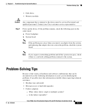
... Virtualization Engine 274 and 474 Hardware Installation Guide 5-7 Contact your Cisco customer service representative. System board Note If the problem goes away when you suspect a networking problem and all the system tests pass, check if there is internal to the device must be encountered, use the following parts in identifying the problems. If possible, have this information available when requesting technical assistance. • Machine type and model • Microprocessor or hard disk upgrades • Failure...
... Virtualization Engine 274 and 474 Hardware Installation Guide 5-7 Contact your Cisco customer service representative. System board Note If the problem goes away when you suspect a networking problem and all the system tests pass, check if there is internal to the device must be encountered, use the following parts in identifying the problems. If possible, have this information available when requesting technical assistance. • Machine type and model • Microprocessor or hard disk upgrades • Failure...

Hardware Installation Guide
Page 63
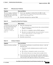
... manual tray-release opening. 3. Check the CD-RW/DVD drive. Table 5-4 General Problems Symptom Cause and Action Problems such as a broken Broken component. The correct device driver is turned on. 2. Cause and Action Reseat all hard disk drives and cables. OL-17739-01 Cisco Wide Area Virtualization Engine 274 and 474 Hardware Installation Guide 5-9 Make sure that the device is installed for the CD-RW/DVD drive. 2. Run the hard disk drive diagnostic tests again. Call your customer service representative. Chapter 5 Troubleshooting...
... manual tray-release opening. 3. Check the CD-RW/DVD drive. Table 5-4 General Problems Symptom Cause and Action Problems such as a broken Broken component. The correct device driver is turned on. 2. Cause and Action Reseat all hard disk drives and cables. OL-17739-01 Cisco Wide Area Virtualization Engine 274 and 474 Hardware Installation Guide 5-9 Make sure that the device is installed for the CD-RW/DVD drive. 2. Run the hard disk drive diagnostic tests again. Call your customer service representative. Chapter 5 Troubleshooting...
Hardware Installation Guide
Page 65
... to the serial port labeled COM1 or CONSOLE a. The console device is designed to use the software. b. If you are using the application, see the "Interpreting POST Diagnostic Front Panel LEDs and Beep Codes" section on your device. OL-17739-01 Cisco Wide Area Virtualization Engine 274 and 474 Hardware Installation Guide 5-11 Cause and Action 1. The software that comes with the WAVE appliance. Check the system board. Your device has the minimum memory needed to operate on...
... to the serial port labeled COM1 or CONSOLE a. The console device is designed to use the software. b. If you are using the application, see the "Interpreting POST Diagnostic Front Panel LEDs and Beep Codes" section on your device. OL-17739-01 Cisco Wide Area Virtualization Engine 274 and 474 Hardware Installation Guide 5-11 Cause and Action 1. The software that comes with the WAVE appliance. Check the system board. Your device has the minimum memory needed to operate on...

Hardware Installation Guide
Page 68
...Power-On Self Test (POST) Chapter 5 Troubleshooting the System Hardware Table 5-10 Diagnostic Front Panel LEDs and Beep Codes (continued) Control Panel Message Description 201-Memory Error RAM failure. 213-Incompatible Memory Module in the error message is missing critical SPD information or is incompatible with the chip set. 214-DIMM Configuration Warning Populated DIMM configuration is not optimized. 219-ECC Memory Module Detected ECC Modules not supported on this Platform Recently added memory module(s) support ECC memory error correction. 301-Keyboard Error Keyboard failure...
...Power-On Self Test (POST) Chapter 5 Troubleshooting the System Hardware Table 5-10 Diagnostic Front Panel LEDs and Beep Codes (continued) Control Panel Message Description 201-Memory Error RAM failure. 213-Incompatible Memory Module in the error message is missing critical SPD information or is incompatible with the chip set. 214-DIMM Configuration Warning Populated DIMM configuration is not optimized. 219-ECC Memory Module Detected ECC Modules not supported on this Platform Recently added memory module(s) support ECC memory error correction. 301-Keyboard Error Keyboard failure...

Hardware Installation Guide
Page 69
... board. OL-17739-01 Cisco Wide Area Virtualization Engine 274 and 474 Hardware Installation Guide 5-15 Drivelock is not properly attached to the USB PlusPower expansion card or to fail. (Some hard drives have a hard drive firmware patch that will fix an erroneous error message.) 1796-SATA Cabling Error One or more SATA hard drives, and they cannot be accessed while the system is configured for RAID mode. 1801-Microcode Patch Error Processor is not supported by ROM BIOS. 2216-Powered USB cable not attached Powered USB cable is enabled...
... board. OL-17739-01 Cisco Wide Area Virtualization Engine 274 and 474 Hardware Installation Guide 5-15 Drivelock is not properly attached to the USB PlusPower expansion card or to fail. (Some hard drives have a hard drive firmware patch that will fix an erroneous error message.) 1796-SATA Cabling Error One or more SATA hard drives, and they cannot be accessed while the system is configured for RAID mode. 1801-Microcode Patch Error Processor is not supported by ROM BIOS. 2216-Powered USB cable not attached Powered USB cable is enabled...

Hardware Installation Guide
Page 70
... Guide OL-17739-01 None Green Power LED flashes every two seconds. Power-On Self Test (POST) Chapter 5 Troubleshooting the System Hardware Table 5-10 Diagnostic Front Panel LEDs and Beep Codes (continued) Control Panel Message Description Network Server Mode Active and No Keyboard Keyboard failure while Network Server Mode Attached enabled. Caution There are no customer-replaceable components inside your WAVE-274 or WAVE-474 appliance. Table 5-11 lists the recommended actions in the order in VSFF chassis. Interpreting POST Diagnostic Front Panel LEDs and Beep Codes...
... Guide OL-17739-01 None Green Power LED flashes every two seconds. Power-On Self Test (POST) Chapter 5 Troubleshooting the System Hardware Table 5-10 Diagnostic Front Panel LEDs and Beep Codes (continued) Control Panel Message Description Network Server Mode Active and No Keyboard Keyboard failure while Network Server Mode Attached enabled. Caution There are no customer-replaceable components inside your WAVE-274 or WAVE-474 appliance. Table 5-11 lists the recommended actions in the order in VSFF chassis. Interpreting POST Diagnostic Front Panel LEDs and Beep Codes...

Hardware Installation Guide
Page 72
... devices such as hard drives, optical drives, and expansion cards. CAUTION: To avoid damage to the DIMMs or the system board, you must unplug the computer power cord before attempting to ensure that is solved. Beeps stop after fifth iteration but LEDs continue until problem is solved. Pre-video memory error. Contact Cisco TAC. 5-18 Cisco Wide Area Virtualization Engine 274 and 474 Hardware Installation Guide OL-17739-01 Power-On Self Test (POST) Chapter 5 Troubleshooting...
... devices such as hard drives, optical drives, and expansion cards. CAUTION: To avoid damage to the DIMMs or the system board, you must unplug the computer power cord before attempting to ensure that is solved. Beeps stop after fifth iteration but LEDs continue until problem is solved. Pre-video memory error. Contact Cisco TAC. 5-18 Cisco Wide Area Virtualization Engine 274 and 474 Hardware Installation Guide OL-17739-01 Power-On Self Test (POST) Chapter 5 Troubleshooting...
Hardware Installation Guide
Page 76
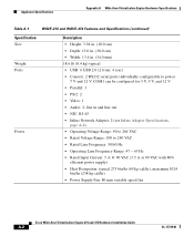
...; Power Supply Fan: 80 mm variable speed fan Cisco Wide Area Virtualization Engine 274 and 474 Hardware Installation Guide A-2 OL-17739-01 Appliance Specifications Appendix A Wide Area Virtualization Engine Hardware Specifications Table A-1 WAVE-274 and WAVE-474 Features and Specifications (continued) Specification Size Weight Ports Power Description • Height: 3.94 in. (10.0 cm) • Depth: 15.0 in. (38.0 cm) • Width: 13.4 in and line out • NIC: RJ-45 • Inline Network Adapter: 2 (see Inline Adapter Specifications...
...; Power Supply Fan: 80 mm variable speed fan Cisco Wide Area Virtualization Engine 274 and 474 Hardware Installation Guide A-2 OL-17739-01 Appliance Specifications Appendix A Wide Area Virtualization Engine Hardware Specifications Table A-1 WAVE-274 and WAVE-474 Features and Specifications (continued) Specification Size Weight Ports Power Description • Height: 3.94 in. (10.0 cm) • Depth: 15.0 in. (38.0 cm) • Width: 13.4 in and line out • NIC: RJ-45 • Inline Network Adapter: 2 (see Inline Adapter Specifications...


