
Software Configuration Guide
Page 28
... fixed at the same priority. This is not recorded on page 2-10 for the FXS interfaces because they are not applicable to write "cpmProcExtPriority" are unsuccessful. 1-12 Cisco VG248 Analog Phone Gateway Software Configuration Guide OL-1209-02 However, because the VG248 runs threads, rather than processes, the MIB is a method that provided by the...
... fixed at the same priority. This is not recorded on page 2-10 for the FXS interfaces because they are not applicable to write "cpmProcExtPriority" are unsuccessful. 1-12 Cisco VG248 Analog Phone Gateway Software Configuration Guide OL-1209-02 However, because the VG248 runs threads, rather than processes, the MIB is a method that provided by the...

Hardware Installation Guide
Page 3
1 C H A P T E R CONTENTS About this Guide vii Overview vii Audience vii Objectives viii Organization viii Related Documentation ix Obtaining Documentation ix World Wide Web ix Documentation CD-ROM ix Ordering Documentation x Documentation Feedback x Obtaining Technical Assistance xi Cisco.com xi Technical Assistance Center xi Contacting TAC by Using the Cisco TAC Website xii Contacting TAC by Telephone xii Overview 1-1 Introduction 1-1 Front Panel 1-3 FXS Telco Connectors 1-3 Status Indicators 1-6 78-13154-01 Cisco VG248 Analog Phone Gateway Hardware Installation Guide iii
1 C H A P T E R CONTENTS About this Guide vii Overview vii Audience vii Objectives viii Organization viii Related Documentation ix Obtaining Documentation ix World Wide Web ix Documentation CD-ROM ix Ordering Documentation x Documentation Feedback x Obtaining Technical Assistance xi Cisco.com xi Technical Assistance Center xi Contacting TAC by Using the Cisco TAC Website xii Contacting TAC by Telephone xii Overview 1-1 Introduction 1-1 Front Panel 1-3 FXS Telco Connectors 1-3 Status Indicators 1-6 78-13154-01 Cisco VG248 Analog Phone Gateway Hardware Installation Guide iii

Hardware Installation Guide
Page 5
Contents A A P P E N D I X B A P P E N D I X Setting the VG248 on a Shelf or Table 3-6 Connecting the VG248 to the Network 3-6 Connecting to the Ethernet Port 3-6 Connecting to the Console Port 3-7 Connecting to the FXS Telco Connectors 3-10 Connecting Power 3-10 Verifying Installation 3-11 Regulatory Compliance and Technical Specifications A-1 Regulatory Compliance A-1 EMI Class A Warnings A-2 ... Disconnecting Device B-18 Safety Cover Requirement B-19 Jewelry Removal Warning B-21 Lightning Activity Warning B-23 78-13154-01 Cisco VG248 Analog Phone Gateway Hardware Installation Guide v
Contents A A P P E N D I X B A P P E N D I X Setting the VG248 on a Shelf or Table 3-6 Connecting the VG248 to the Network 3-6 Connecting to the Ethernet Port 3-6 Connecting to the Console Port 3-7 Connecting to the FXS Telco Connectors 3-10 Connecting Power 3-10 Verifying Installation 3-11 Regulatory Compliance and Technical Specifications A-1 Regulatory Compliance A-1 EMI Class A Warnings A-2 ... Disconnecting Device B-18 Safety Cover Requirement B-19 Jewelry Removal Warning B-21 Lightning Activity Warning B-23 78-13154-01 Cisco VG248 Analog Phone Gateway Hardware Installation Guide v

Hardware Installation Guide
Page 13
... call waiting, caller ID, call transfer, and call transfer. These sections provide an overview of the entire device. 78-13154-01 Cisco VG248 Analog Phone Gateway Hardware Installation Guide 1-1 It includes 48 FXS port interfaces to connect directly to a normal central office (CO) or PBX line, supporting features such as if they are connected...
... call waiting, caller ID, call transfer, and call transfer. These sections provide an overview of the entire device. 78-13154-01 Cisco VG248 Analog Phone Gateway Hardware Installation Guide 1-1 It includes 48 FXS port interfaces to connect directly to a normal central office (CO) or PBX line, supporting features such as if they are connected...

Hardware Installation Guide
Page 15
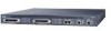
... (REN) load-3 per line, and only two phones per line can be off-hook at any one time 78-13154-01 Cisco VG248 Analog Phone Gateway Hardware Installation Guide 1-3 Figure 1-2 VG248 Front Panel 58952 1 2 1 2 3 4 6 5 7 1 FXS telco connectors, ports 1-24 and 25-48 5 System status indicators 2 Port status indicators, ports 1-24 and 25-48 6 Ethernet port...
... (REN) load-3 per line, and only two phones per line can be off-hook at any one time 78-13154-01 Cisco VG248 Analog Phone Gateway Hardware Installation Guide 1-3 Figure 1-2 VG248 Front Panel 58952 1 2 1 2 3 4 6 5 7 1 FXS telco connectors, ports 1-24 and 25-48 5 System status indicators 2 Port status indicators, ports 1-24 and 25-48 6 Ethernet port...

Hardware Installation Guide
Page 16
Table 1-1 FXS Ports 1-24 Connector Pinouts Pin Number 1, 26 2, 27 3, 28 4,29 5, 30 6,31 7, 32 8, 33 9, 34 10, 35 11, 36 12, 37 13, 38 14, 39 ... Port 19 transmit/receive Port 20 transmit/receive Port 21 transmit/receive Port 22 transmit/receive Port 23 transmit/receive Cisco VG248 Analog Phone Gateway Hardware Installation Guide 1-4 78-13154-01 Table 1-1 describes the FXS connector pinouts for both directions. Front Panel Chapter 1 Overview • Voice activity detection • Supported codecs-G.711 and G.729a...
Table 1-1 FXS Ports 1-24 Connector Pinouts Pin Number 1, 26 2, 27 3, 28 4,29 5, 30 6,31 7, 32 8, 33 9, 34 10, 35 11, 36 12, 37 13, 38 14, 39 ... Port 19 transmit/receive Port 20 transmit/receive Port 21 transmit/receive Port 22 transmit/receive Port 23 transmit/receive Cisco VG248 Analog Phone Gateway Hardware Installation Guide 1-4 78-13154-01 Table 1-1 describes the FXS connector pinouts for both directions. Front Panel Chapter 1 Overview • Voice activity detection • Supported codecs-G.711 and G.729a...

Hardware Installation Guide
Page 17
... 1-24 Connector Pinouts (continued) Pin Number 24, 49 25, 50 Function Port 24 transmit/receive Unused Table 1-2 describes the FXS connector pinouts for ports 25-48. Table 1-2 FXS Ports 25-48 Connector Pinouts Pin Number Function 1, 26 Port 25 transmit/receive 2, 27 Port 26 transmit/receive 3, 28 Port 27 transmit/receive 4,29.../receive 17, 42 Port 41 transmit/receive 18, 43 Port 42 transmit/receive 19, 44 Port 43 transmit/receive 20, 45 Port 44 transmit/receive Cisco VG248 Analog Phone Gateway Hardware Installation Guide 1-5
... 1-24 Connector Pinouts (continued) Pin Number 24, 49 25, 50 Function Port 24 transmit/receive Unused Table 1-2 describes the FXS connector pinouts for ports 25-48. Table 1-2 FXS Ports 25-48 Connector Pinouts Pin Number Function 1, 26 Port 25 transmit/receive 2, 27 Port 26 transmit/receive 3, 28 Port 27 transmit/receive 4,29.../receive 17, 42 Port 41 transmit/receive 18, 43 Port 42 transmit/receive 19, 44 Port 43 transmit/receive 20, 45 Port 44 transmit/receive Cisco VG248 Analog Phone Gateway Hardware Installation Guide 1-5

Hardware Installation Guide
Page 18
Front Panel Chapter 1 Overview Table 1-2 FXS Ports 25-48 Connector Pinouts (continued) Pin Number Function 21, 46 Port 45 transmit/receive 22, 47 Port 46 transmit/receive 23, 48 Port 47 ... on the front panel display the VG248 status: • Port Status Indicators • System Status Indicators • Ethernet Status Indicators Table 1-3 includes descriptions of the LED states of these status indicators. Check the event log for details. Console link not connected Not operating normally Cisco VG248 Analog Phone Gateway Hardware Installation Guide 1-6 78-13154...
Front Panel Chapter 1 Overview Table 1-2 FXS Ports 25-48 Connector Pinouts (continued) Pin Number Function 21, 46 Port 45 transmit/receive 22, 47 Port 46 transmit/receive 23, 48 Port 47 ... on the front panel display the VG248 status: • Port Status Indicators • System Status Indicators • Ethernet Status Indicators Table 1-3 includes descriptions of the LED states of these status indicators. Check the event log for details. Console link not connected Not operating normally Cisco VG248 Analog Phone Gateway Hardware Installation Guide 1-6 78-13154...

Hardware Installation Guide
Page 36
...FXS Telco Connectors, page 3-10 • Connecting Power, page 3-10 Connecting to the Ethernet Port Use the Ethernet port to connect the VG248 to the IP network to telephone-network voltage (TNV) circuits. The VG248 supports half- Connecting the VG248 to the Network Chapter 3 Installing the VG248 Setting the VG248...or other IP telephony systems in the network, such as Cisco CallManager. or full-duplex Ethernet operation. Some LAN and WAN ports both use RJ-45 connectors. Cisco VG248 Analog Phone Gateway Hardware Installation Guide 3-6 78-13154-01 Use caution when ...
...FXS Telco Connectors, page 3-10 • Connecting Power, page 3-10 Connecting to the Ethernet Port Use the Ethernet port to connect the VG248 to the IP network to telephone-network voltage (TNV) circuits. The VG248 supports half- Connecting the VG248 to the Network Chapter 3 Installing the VG248 Setting the VG248...or other IP telephony systems in the network, such as Cisco CallManager. or full-duplex Ethernet operation. Some LAN and WAN ports both use RJ-45 connectors. Cisco VG248 Analog Phone Gateway Hardware Installation Guide 3-6 78-13154-01 Use caution when ...

Hardware Installation Guide
Page 40
Figure 3-6 Connecting to the Telco Connectors on the VG248 58934 1 1 1 FXS telco connectors Connecting Power Provide power to the analog devices (see Figure 3-7). 3-10 Cisco VG248 Analog Phone Gateway Hardware Installation Guide 78-13154-01 Connecting the VG248 to the Network Chapter 3 Installing the VG248 Connecting to the FXS Telco Connectors Use one of the two 24-port FXS telco connectors to connect the VG248 to the VG248 by plugging the power cord (included) into the AC power adapter on the rear panel (see Figure 3-6).
Figure 3-6 Connecting to the Telco Connectors on the VG248 58934 1 1 1 FXS telco connectors Connecting Power Provide power to the analog devices (see Figure 3-7). 3-10 Cisco VG248 Analog Phone Gateway Hardware Installation Guide 78-13154-01 Connecting the VG248 to the Network Chapter 3 Installing the VG248 Connecting to the FXS Telco Connectors Use one of the two 24-port FXS telco connectors to connect the VG248 to the VG248 by plugging the power cord (included) into the AC power adapter on the rear panel (see Figure 3-6).

Hardware Installation Guide
Page 81
..., description 1-8 connecting console port 3-7 Ethernet port 3-6 FXS connectors 3-10 console port connecting to 3-7 pinouts 1-7 INDEX D documentation, organization viii E electricity, interference considerations 2-7 EMI, preventing 2-7 ESD, preventing 2-6 Ethernet port connecting to 3-6 pinouts 1-7 F front panel, description 1-3 FXS connectors connecting to 3-10 description 1-3 pinouts 1-4 G grounding, the system 2-3 78-13154-01 Cisco VG248 Analog Phone Gateway Hardware Installation Guide IN-1
..., description 1-8 connecting console port 3-7 Ethernet port 3-6 FXS connectors 3-10 console port connecting to 3-7 pinouts 1-7 INDEX D documentation, organization viii E electricity, interference considerations 2-7 EMI, preventing 2-7 ESD, preventing 2-6 Ethernet port connecting to 3-6 pinouts 1-7 F front panel, description 1-3 FXS connectors connecting to 3-10 description 1-3 pinouts 1-4 G grounding, the system 2-3 78-13154-01 Cisco VG248 Analog Phone Gateway Hardware Installation Guide IN-1

Hardware Installation Guide
Page 82
..., ensuring 2-2 P pinouts console port 1-7 Ethernet port 1-7 FXS connectors 1-4 power connector, location 1-8 disconnecting, for removal 2-7 requirements 1-8 safety considerations 2-5 preventing EMI 2-7 ESD 2-6 R rack, installing VG248 in 3-1 rear panel, description 1-8 RFI 2-7 S safety warnings for installation 2-8 shelf, placing VG248 on 3-6 site installation, choosing 2-2 status indicators Ethernet 1-7 ports 1-6 system 1-6 IN-2 Cisco VG248 Analog Phone Gateway Hardware Installation Guide 78-13154-01
..., ensuring 2-2 P pinouts console port 1-7 Ethernet port 1-7 FXS connectors 1-4 power connector, location 1-8 disconnecting, for removal 2-7 requirements 1-8 safety considerations 2-5 preventing EMI 2-7 ESD 2-6 R rack, installing VG248 in 3-1 rear panel, description 1-8 RFI 2-7 S safety warnings for installation 2-8 shelf, placing VG248 on 3-6 site installation, choosing 2-2 status indicators Ethernet 1-7 ports 1-6 system 1-6 IN-2 Cisco VG248 Analog Phone Gateway Hardware Installation Guide 78-13154-01

Hardware Installation Guide
Page 83
Index T telco connectors, see FXS connectors V verifying, installation 3-11 W wiring interference 2-7 78-13154-01 Cisco VG248 Analog Phone Gateway Hardware Installation Guide IN-3
Index T telco connectors, see FXS connectors V verifying, installation 3-11 W wiring interference 2-7 78-13154-01 Cisco VG248 Analog Phone Gateway Hardware Installation Guide IN-3