
Getting Started Guide
Page 12
... voice interfaces, or additional LAN interfaces • PC with 32- Cisco Smart Business Communications System Software and Documentation CD-ROM A separate rack-mount kit (Part Number: 53-2993-01) can be required: • Cisco Unified IP phones • Cables for connecting phones • Cable for... power supply (included with the product: • Accessory kit containing: - Installing Components for Cisco Unified Communications 500 Series for Small Business Items Not Included These additional items might be ordered for using web-...
... voice interfaces, or additional LAN interfaces • PC with 32- Cisco Smart Business Communications System Software and Documentation CD-ROM A separate rack-mount kit (Part Number: 53-2993-01) can be required: • Cisco Unified IP phones • Cables for connecting phones • Cable for... power supply (included with the product: • Accessory kit containing: - Installing Components for Cisco Unified Communications 500 Series for Small Business Items Not Included These additional items might be ordered for using web-...

Getting Started Guide
Page 24
Use a number 2 Phillips screwdriver to the sides of the chassis as shown in the rack-mount kit for Rack-Mounting Power Supply 2 1 242823 1 Wall-mount bracket 24 2 Rack-mount bracket 242820 Step 1 Attach the mounting brackets to install the bracket screws. Figure 8 Attaching Rack-Mount Brackets to the 8- Use four screws on each side. and 16-user models only.) Figure 9 Brackets for the power supply. (This step applies to the UC 520 1 VIC 4FXS/DID 3 2 1 0 IN USE 00 Step 2 Figure 9 shows the brackets in Figure 8, using the screws provided.
Use a number 2 Phillips screwdriver to the sides of the chassis as shown in the rack-mount kit for Rack-Mounting Power Supply 2 1 242823 1 Wall-mount bracket 24 2 Rack-mount bracket 242820 Step 1 Attach the mounting brackets to install the bracket screws. Figure 8 Attaching Rack-Mount Brackets to the 8- Use four screws on each side. and 16-user models only.) Figure 9 Brackets for the power supply. (This step applies to the UC 520 1 VIC 4FXS/DID 3 2 1 0 IN USE 00 Step 2 Figure 9 shows the brackets in Figure 8, using the screws provided.
Getting Started Guide
Page 25
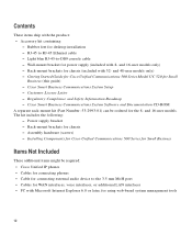
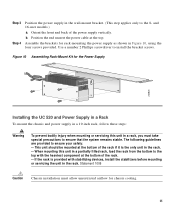
... to the 8- This unit should be mounted at the top. The following guidelines are provided to install the bracket screws. Figure 10 Assembling Rack-Mount Kit for the Power Supply 242824 Installing the UC 520 and Power Supply in a Rack To mount the chassis and power supply in a 19-inch rack...
... to the 8- This unit should be mounted at the top. The following guidelines are provided to install the bracket screws. Figure 10 Assembling Rack-Mount Kit for the Power Supply 242824 Installing the UC 520 and Power Supply in a Rack To mount the chassis and power supply in a 19-inch rack...

Getting Started Guide
Page 37
... switch on a desktop, table, or shelf, observe the following steps: Step 1 Step 2 Locate the adhesive strip with the rubber feet in the accessory kit. Desktop Installation When installing a Cisco Catalyst Express 520 on a desktop, table, or shelf, perform the following precautions: Warning The plug-socket combination must allow unrestricted airflow for unrestricted...
... switch on a desktop, table, or shelf, observe the following steps: Step 1 Step 2 Locate the adhesive strip with the rubber feet in the accessory kit. Desktop Installation When installing a Cisco Catalyst Express 520 on a desktop, table, or shelf, perform the following precautions: Warning The plug-socket combination must allow unrestricted airflow for unrestricted...

