Hardware Installation Guide
Page 3
... a Service Request 18 Definitions of Service Request Severity 19 Obtaining Additional Publications and Information 19 Product Overview 1 Product Description 1 Cisco uBR7100 Series Models 2 Cisco uBR7111 and Cisco uBR7111E 2 Cisco uBR7114 and Cisco uBR7114E 2 Cisco uBR7100 Series Router Operational Features 2 Cisco uBR7100 Series Routers Physical Description 3 Fixed Interface Units 6 Ethernet/Fast Ethernet LAN Interface 6 RF Cable Interface 6 Field-Replaceable Units 7 Port Adapters...
... a Service Request 18 Definitions of Service Request Severity 19 Obtaining Additional Publications and Information 19 Product Overview 1 Product Description 1 Cisco uBR7100 Series Models 2 Cisco uBR7111 and Cisco uBR7111E 2 Cisco uBR7114 and Cisco uBR7114E 2 Cisco uBR7100 Series Router Operational Features 2 Cisco uBR7100 Series Routers Physical Description 3 Fixed Interface Units 6 Ethernet/Fast Ethernet LAN Interface 6 RF Cable Interface 6 Field-Replaceable Units 7 Port Adapters...
Hardware Installation Guide
Page 7
.... Audience To use the appropriate companion publications to all models of the Cisco uBR7100 series universal broadband router, including the Cisco uBR7111, Cisco uBR7111E, Cisco uBR7114, and Cisco uBR7114E routers. It contains procedures for Cisco uBR7100 series routers. For a list of the Cisco uBR7100 Series and Cisco uBR7100E Series Universal Broadband Router Hardware Installation Guide, its intended audience, its organization, and its document conventions...
.... Audience To use the appropriate companion publications to all models of the Cisco uBR7100 series universal broadband router, including the Cisco uBR7111, Cisco uBR7111E, Cisco uBR7114, and Cisco uBR7114E routers. It contains procedures for Cisco uBR7100 series routers. For a list of the Cisco uBR7100 Series and Cisco uBR7100E Series Universal Broadband Router Hardware Installation Guide, its intended audience, its organization, and its document conventions...
Hardware Installation Guide
Page 21
...range. The downstream uses a 6 MHz channel width in the 5 to all models of the Cisco uBR7100 series universal broadband router, including the Cisco uBR7111, Cisco uBR7111E, Cisco uBR7114, and Cisco uBR7114E routers. DOCSIS supports the 6 MHz North American channel plans using the ITU J.112 Annex A RF ... P T E R 1 This chapter provides physical and functional overviews of Cisco uBR7100 series universal broadband routers and contains the following two standards: • The Cisco uBR7111 and Cisco uBR7114 support the Data-over a coaxial cable connection. The downstream uses an 8 ...
...range. The downstream uses a 6 MHz channel width in the 5 to all models of the Cisco uBR7100 series universal broadband router, including the Cisco uBR7111, Cisco uBR7111E, Cisco uBR7114, and Cisco uBR7114E routers. DOCSIS supports the 6 MHz North American channel plans using the ITU J.112 Annex A RF ... P T E R 1 This chapter provides physical and functional overviews of Cisco uBR7100 series universal broadband routers and contains the following two standards: • The Cisco uBR7111 and Cisco uBR7114 support the Data-over a coaxial cable connection. The downstream uses an 8 ...
Hardware Installation Guide
Page 22
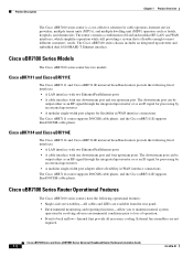
... the Cisco uBR7114E supports EuroDOCSIS cable plants. Cisco uBR7100 Series and Cisco uBR7100E Series Universal Broadband Router Hardware Installation Guide 1-2 OL-5916-01 Cisco uBR7111 and Cisco uBR7111E The Cisco uBR7111 and Cisco uBR7111E universal broadband routers provide the following fixed interfaces: • A LAN interface with two Ethernet/FastEthernet ports • A cable interface with one upstream port. Cisco uBR7114 and Cisco uBR7114E The Cisco uBR7114 and Cisco uBR7114E...
... the Cisco uBR7114E supports EuroDOCSIS cable plants. Cisco uBR7100 Series and Cisco uBR7100E Series Universal Broadband Router Hardware Installation Guide 1-2 OL-5916-01 Cisco uBR7111 and Cisco uBR7111E The Cisco uBR7111 and Cisco uBR7111E universal broadband routers provide the following fixed interfaces: • A LAN interface with two Ethernet/FastEthernet ports • A cable interface with one upstream port. Cisco uBR7114 and Cisco uBR7114E The Cisco uBR7114 and Cisco uBR7114E...

Hardware Installation Guide
Page 24
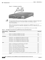
...shows the rear panel of the router. Figure 1-2 shows the rear panel of the Cisco uBR7114 and Cisco uBR7114E routers. Cisco uBR7100 Series and Cisco uBR7100E Series Universal Broadband Router Hardware Installation Guide 1-4 OL-5916-01 Figure 1-1 Cisco uBR7111 and Cisco uBR7111E Universal Broadband Router-Rear Panel View 4 3 ... 6 Power supply 7 Console and auxiliary ports 8 US0 9 DS0 10 Module slot (not used) 11 DS0 RF Figure 1-2 Cisco uBR7114 and Cisco uBR7114E Universal Broadband Router-Rear Panel View 4 3 2 1 116835 5 I DS0 RF DS0 US3 ACT ACT LNK FE 0/0 FE 0/1 1 US2 ...
...shows the rear panel of the router. Figure 1-2 shows the rear panel of the Cisco uBR7114 and Cisco uBR7114E routers. Cisco uBR7100 Series and Cisco uBR7100E Series Universal Broadband Router Hardware Installation Guide 1-4 OL-5916-01 Figure 1-1 Cisco uBR7111 and Cisco uBR7111E Universal Broadband Router-Rear Panel View 4 3 ... 6 Power supply 7 Console and auxiliary ports 8 US0 9 DS0 10 Module slot (not used) 11 DS0 RF Figure 1-2 Cisco uBR7114 and Cisco uBR7114E Universal Broadband Router-Rear Panel View 4 3 2 1 116835 5 I DS0 RF DS0 US3 ACT ACT LNK FE 0/0 FE 0/1 1 US2 ...

Hardware Installation Guide
Page 26
...a 5 to process the signal for installing the router on a tabletop, installing the router in an equipment rack, and attaching the cable-management bracket are given in Chapter 3, "Installing Cisco uBR7100 Series Universal Broadband Routers." On the Cisco uBR7111E and Cisco uBR7114E routers, the cable interface supports the EuroDOCSIS channel plan...with 64 QAM and 256 QAM data rates, while the upstream supports QPSK and 16 QAM data rates. Note On the Cisco uBR7111E and Cisco uBR7114E routers, the DS0 connector is automatically muted when the DS0 RF port is a 10-Mbps 10BASE-T Ethernet or a 100-...
...a 5 to process the signal for installing the router on a tabletop, installing the router in an equipment rack, and attaching the cable-management bracket are given in Chapter 3, "Installing Cisco uBR7100 Series Universal Broadband Routers." On the Cisco uBR7111E and Cisco uBR7114E routers, the cable interface supports the EuroDOCSIS channel plan...with 64 QAM and 256 QAM data rates, while the upstream supports QPSK and 16 QAM data rates. Note On the Cisco uBR7111E and Cisco uBR7114E routers, the DS0 connector is automatically muted when the DS0 RF port is a 10-Mbps 10BASE-T Ethernet or a 100-...
Hardware Installation Guide
Page 27
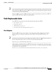
... used for local monitoring purposes. Note For the most current information on the network at any one upstream port, and the Cisco uBR7114 and Cisco uBR7114E routers support four upstream ports. The Cisco uBR7111 and Cisco uBR7111E routers support one time. Chapter 1 Product Overview Field-Replaceable Units Note Only one downstream connector should be used for data traffic...
... used for local monitoring purposes. Note For the most current information on the network at any one upstream port, and the Cisco uBR7114 and Cisco uBR7114E routers support four upstream ports. The Cisco uBR7111 and Cisco uBR7111E routers support one time. Chapter 1 Product Overview Field-Replaceable Units Note Only one downstream connector should be used for data traffic...
Hardware Installation Guide
Page 28
...OL-5916-01 The product number for the blank port adapter is MAS-7100-PABLANK=. Table 1-1 lists and describes the port adapters supported by Cisco uBR7100 series routers. Field-Replaceable Units Figure 1-4 Port Adapter Locking Tabs Locked Unlocked Chapter 1 Product Overview 36092 5 I DS0 RF DS0 US3 ACT ACT LNK... FE 0/0 FE 0/1 1 US2 SLOT 0 SLOT 1 US1 US0 PWR CONS SYS AUX RDY EN uBR7114 Caution To ensure adequate airflow across the router port adapters, a port adapter or a blank port adapter must be installed in each port adapter slot.
...OL-5916-01 The product number for the blank port adapter is MAS-7100-PABLANK=. Table 1-1 lists and describes the port adapters supported by Cisco uBR7100 series routers. Field-Replaceable Units Figure 1-4 Port Adapter Locking Tabs Locked Unlocked Chapter 1 Product Overview 36092 5 I DS0 RF DS0 US3 ACT ACT LNK... FE 0/0 FE 0/1 1 US2 SLOT 0 SLOT 1 US1 US0 PWR CONS SYS AUX RDY EN uBR7114 Caution To ensure adequate airflow across the router port adapters, a port adapter or a blank port adapter must be installed in each port adapter slot.

Hardware Installation Guide
Page 32
... follows: • Slot 0-Fixed LAN (Fast Ethernet) interface • Slot 1-Fixed RF interface • Slot 3-Modular port adapter Note Slots 2, 4, and 5 are not used on Cisco uBR7114 and Cisco uBR7114E routers. Functional Overview Chapter 1 Product Overview Rack-Mount and Cable-Management Kit The rack-mount and cable-management kit for...
... follows: • Slot 0-Fixed LAN (Fast Ethernet) interface • Slot 1-Fixed RF interface • Slot 3-Modular port adapter Note Slots 2, 4, and 5 are not used on Cisco uBR7114 and Cisco uBR7114E routers. Functional Overview Chapter 1 Product Overview Rack-Mount and Cable-Management Kit The rack-mount and cable-management kit for...

Hardware Installation Guide
Page 33
... commands. The following example, most of the status information for each interface in the Software You can identify interfaces by using Cisco IOS commands. To display information about all interfaces, use the show interfaces command with the interface type, slot number, and ... US3 ACT ACT LNK FE 0/0 FE 0/1 1 US2 SLOT 0 SLOT 1 US1 US0 PWR CONS SYS AUX RDY EN uBR7114 Slot 1 Note The slots for each interface is omitted: Router# show interfaces type slot/port. In the following example shows how the show interfaces command. Indentifing Interface Information in...
... commands. The following example, most of the status information for each interface in the Software You can identify interfaces by using Cisco IOS commands. To display information about all interfaces, use the show interfaces command with the interface type, slot number, and ... US3 ACT ACT LNK FE 0/0 FE 0/1 1 US2 SLOT 0 SLOT 1 US1 US0 PWR CONS SYS AUX RDY EN uBR7114 Slot 1 Note The slots for each interface is omitted: Router# show interfaces type slot/port. In the following example shows how the show interfaces command. Indentifing Interface Information in...

Hardware Installation Guide
Page 38
... router shows sample output from power-on X.25 software, Version 3.0.0. The following example using Cisco IOS commands. National clock card with an RJ-45 receptacle. Configuration register is 0x0 Other Interfaces Console port-Provides access for a local terminal and is "ubr7100-p-mz" cisco uBR7114... 2 MB (fixed) - Identifying the Network Processor and the Cisco IOS Release Software Version To identify the processor and software version installed in your Cisco uBR7100 series router, use the show version Cisco Internetwork Operating System Software IOS (tm) EGR Software (UBR7100-P-M), ...
... router shows sample output from power-on X.25 software, Version 3.0.0. The following example using Cisco IOS commands. National clock card with an RJ-45 receptacle. Configuration register is 0x0 Other Interfaces Console port-Provides access for a local terminal and is "ubr7100-p-mz" cisco uBR7114... 2 MB (fixed) - Identifying the Network Processor and the Cisco IOS Release Software Version To identify the processor and software version installed in your Cisco uBR7100 series router, use the show version Cisco Internetwork Operating System Software IOS (tm) EGR Software (UBR7100-P-M), ...

Hardware Installation Guide
Page 39
...RF DS0 RF DS0 DS0 DS0 ACT ACT LNK FE 0/0 FE 0/1 1 SLOT 0 SLOT 1 US0 PWR CONS SYS AUX RDY EN uBR7114 EN Card Enable US0 U0 Enable Figure 1-8 Cisco uBR7114 System LEDs ACT ACT Active Active Link Link LNK LNK 21 PWR Power Sys Rdy SYS RDY 36455 5 I DS0 RF RF DS0...DS0 US3 ACT ACT LNK FE 0/0 FE 0/1 1 US2 SLOT 0 SLOT 1 US1 US0 PWR CONS SYS AUX RDY EN uBR7114 DS0 DS0 US3 U3 Enable US2 U2 Enable EN Card Enable US0 U0 Enable US1 U1 Enable OL-5916-01 Cisco uBR7100 Series and Cisco uBR7100E Series Universal Broadband Router Hardware Installation Guide 1-19
...RF DS0 RF DS0 DS0 DS0 ACT ACT LNK FE 0/0 FE 0/1 1 SLOT 0 SLOT 1 US0 PWR CONS SYS AUX RDY EN uBR7114 EN Card Enable US0 U0 Enable Figure 1-8 Cisco uBR7114 System LEDs ACT ACT Active Active Link Link LNK LNK 21 PWR Power Sys Rdy SYS RDY 36455 5 I DS0 RF RF DS0...DS0 US3 ACT ACT LNK FE 0/0 FE 0/1 1 US2 SLOT 0 SLOT 1 US1 US0 PWR CONS SYS AUX RDY EN uBR7114 DS0 DS0 US3 U3 Enable US2 U2 Enable EN Card Enable US0 U0 Enable US1 U1 Enable OL-5916-01 Cisco uBR7100 Series and Cisco uBR7100E Series Universal Broadband Router Hardware Installation Guide 1-19

Hardware Installation Guide
Page 47
... use all the screws and the brackets provided to secure the chassis to the rack posts. • If you are identical. Figure 2-2 Cisco uBR7114 Router Footprint and Outer Dimensions 23.25 in. (59 cm) Chassis depth including cables Chassis depth 18.25 in. (46.36 cm) 22136 ...43.18 cm). • The height of the chassis is constructed to use the rack-mount kit designed for Cisco uBR7100 series routers. The dimensions for the Cisco uBR7114 universal broadband router. Figure 2-2 shows the chassis footprint, which you need if you plan to support the weight and dimensions of the...
... use all the screws and the brackets provided to secure the chassis to the rack posts. • If you are identical. Figure 2-2 Cisco uBR7114 Router Footprint and Outer Dimensions 23.25 in. (59 cm) Chassis depth including cables Chassis depth 18.25 in. (46.36 cm) 22136 ...43.18 cm). • The height of the chassis is constructed to use the rack-mount kit designed for Cisco uBR7100 series routers. The dimensions for the Cisco uBR7114 universal broadband router. Figure 2-2 shows the chassis footprint, which you need if you plan to support the weight and dimensions of the...

Hardware Installation Guide
Page 61
...for installing the cable-management bracket on the bracket are facing away from the chassis. OL-5916-01 Cisco uBR7100 Series and Cisco uBR7100E Series Universal Broadband Router Hardware Installation Guide 3-7 Attach the cable-management bracket to the two grounding receptacles that the two flanges ... the appropriate grounding point at your site to ensure an adequate chassis ground. Use tie wraps to secure interface cables to the Cisco uBR7114 or Cisco uBR7114E chassis; Figure 3-8 shows how to attach the cable-management brackets to the bracket flanges. Step 2 Step 3 Align the cable...
...for installing the cable-management bracket on the bracket are facing away from the chassis. OL-5916-01 Cisco uBR7100 Series and Cisco uBR7100E Series Universal Broadband Router Hardware Installation Guide 3-7 Attach the cable-management bracket to the two grounding receptacles that the two flanges ... the appropriate grounding point at your site to ensure an adequate chassis ground. Use tie wraps to secure interface cables to the Cisco uBR7114 or Cisco uBR7114E chassis; Figure 3-8 shows how to attach the cable-management brackets to the bracket flanges. Step 2 Step 3 Align the cable...

Hardware Installation Guide
Page 62
...or connect or disconnect cables during periods of whether power to external upconverter) Downstream port (integrated upconverter) Cisco uBR7100 Series and Cisco uBR7100E Series Universal Broadband Router Hardware Installation Guide 3-8 OL-5916-01 Warning Do not work on installing port adapters, see Appendix C, ...SLOT 0 SLOT 1 US1 US0 PWR CONS SYS AUX RDY EN uBR7114 US2 US1 US0 Upstream ports Downstream port (to the unit is not being used, it has been processed by the Cisco uBR7100 series integrated upconverter. Statement 1026 Connecting Upstream and Downstream Ports ...
...or connect or disconnect cables during periods of whether power to external upconverter) Downstream port (integrated upconverter) Cisco uBR7100 Series and Cisco uBR7100E Series Universal Broadband Router Hardware Installation Guide 3-8 OL-5916-01 Warning Do not work on installing port adapters, see Appendix C, ...SLOT 0 SLOT 1 US1 US0 PWR CONS SYS AUX RDY EN uBR7114 US2 US1 US0 Upstream ports Downstream port (to the unit is not being used, it has been processed by the Cisco uBR7100 series integrated upconverter. Statement 1026 Connecting Upstream and Downstream Ports ...

Hardware Installation Guide
Page 63
...PC or other Ethernet device. • Use Category 5 UTP straight-through Ethernet cable OL-5916-01 Cisco uBR7100 Series and Cisco uBR7100E Series Universal Broadband Router Hardware Installation Guide 3-9 Attach the appropriate cable directly to a PC or other Ethernet device. these cables ...DS0 US3 ACT ACT LNK FE 0/0 FE 0/1 1 US2 SLOT 0 SLOT 1 US1 US0 PWR CONS SYS AUX RDY EN uBR7114 10BASE-T/100BASE-TX ports Fast Ethernet 0/0 (RJ-45) Cisco uBR7100 series router Ethernet hub 8 7 6 5 4 3 2 1 Straight-through cables when connecting 100BASE-TX to a hub. • Use...
...PC or other Ethernet device. • Use Category 5 UTP straight-through Ethernet cable OL-5916-01 Cisco uBR7100 Series and Cisco uBR7100E Series Universal Broadband Router Hardware Installation Guide 3-9 Attach the appropriate cable directly to a PC or other Ethernet device. these cables ...DS0 US3 ACT ACT LNK FE 0/0 FE 0/1 1 US2 SLOT 0 SLOT 1 US1 US0 PWR CONS SYS AUX RDY EN uBR7114 10BASE-T/100BASE-TX ports Fast Ethernet 0/0 (RJ-45) Cisco uBR7100 series router Ethernet hub 8 7 6 5 4 3 2 1 Straight-through cables when connecting 100BASE-TX to a hub. • Use...

Hardware Installation Guide
Page 64
... 5 I DS0 RF DS0 US3 ACT ACT LNK FE 0/0 FE 0/1 1 US2 SLOT 0 SLOT 1 US1 US0 PWR CONS SYS AUX RDY EN uBR7114 Console port (RJ-45) Cisco uBR7100 series router PC (laptop) RJ-45-to-RJ-45 rollover cable RJ-45-to-DB-9 adapter (labeled TERMINAL) 3-10...the RJ-45-to-DB-9 adapter (labeled TERMINAL). Connecting the Console Port and Auxiliary Port Chapter 3 Installing Cisco uBR7100 Series Universal Broadband Routers Connecting the Console Port and Auxiliary Port The router arrives with a console and auxiliary cable kit, which contains the cable and adapters you need to connect a...
... 5 I DS0 RF DS0 US3 ACT ACT LNK FE 0/0 FE 0/1 1 US2 SLOT 0 SLOT 1 US1 US0 PWR CONS SYS AUX RDY EN uBR7114 Console port (RJ-45) Cisco uBR7100 series router PC (laptop) RJ-45-to-RJ-45 rollover cable RJ-45-to-DB-9 adapter (labeled TERMINAL) 3-10...the RJ-45-to-DB-9 adapter (labeled TERMINAL). Connecting the Console Port and Auxiliary Port Chapter 3 Installing Cisco uBR7100 Series Universal Broadband Routers Connecting the Console Port and Auxiliary Port The router arrives with a console and auxiliary cable kit, which contains the cable and adapters you need to connect a...

Hardware Installation Guide
Page 65
...CONS SYS AUX RDY EN uBR7114 Auxiliary port (RJ-45) Modem RJ-45-to-DB-25 adapter (labeled MODEM) Step 3 Step 4 Attach the DB-25 connector to the modem. (See Figure 3-12.) Make sure that the modem and the auxiliary port on the router are configured for either ...the console port and auxiliary port connectors, see the "Console and Auxiliary Port Cables and Pinouts" section on page C-2. Chapter 3 Installing Cisco uBR7100 Series Universal Broadband Routers Connecting the Console Port and Auxiliary Port Step 3 Step 4 Attach the DB-9 connector to the appropriate serial connector on the PC or...
...CONS SYS AUX RDY EN uBR7114 Auxiliary port (RJ-45) Modem RJ-45-to-DB-25 adapter (labeled MODEM) Step 3 Step 4 Attach the DB-25 connector to the modem. (See Figure 3-12.) Make sure that the modem and the auxiliary port on the router are configured for either ...the console port and auxiliary port connectors, see the "Console and Auxiliary Port Cables and Pinouts" section on page C-2. Chapter 3 Installing Cisco uBR7100 Series Universal Broadband Routers Connecting the Console Port and Auxiliary Port Step 3 Step 4 Attach the DB-9 connector to the appropriate serial connector on the PC or...

Hardware Installation Guide
Page 66
... US3 ACT ACT LNK FE 0/0 FE 0/1 1 US2 SLOT 0 SLOT 1 US1 US0 PWR CONS SYS AUX RDY EN uBR7114 Note For information on system startup and software configuration, see Appendix A, "System Specifications". Cisco uBR7100 series routers have one end of the power cord to the power connector on . For systems without a power switch, line...
... US3 ACT ACT LNK FE 0/0 FE 0/1 1 US2 SLOT 0 SLOT 1 US1 US0 PWR CONS SYS AUX RDY EN uBR7114 Note For information on system startup and software configuration, see Appendix A, "System Specifications". Cisco uBR7100 series routers have one end of the power cord to the power connector on . For systems without a power switch, line...

Hardware Installation Guide
Page 69
...DS0 RF DS0 DS0 DS0 ACT ACT LNK FE 0/0 FE 0/1 1 SLOT 0 SLOT 1 US0 PWR CONS SYS AUX RDY EN uBR7114 EN Card Enable US0 U0 Enable Figure 4-2 Cisco uBR7114 System LEDs ACT ACT Active Active Link Link LNK LNK 21 PWR Power Sys Rdy SYS RDY 36455 5 I DS0 RF RF ...1 US2 SLOT 0 SLOT 1 US1 US0 PWR CONS SYS AUX RDY EN uBR7114 DS0 DS0 US3 U3 Enable US2 U2 Enable EN Card Enable US0 U0 Enable US1 U1 Enable OL-5916-01 Cisco uBR7100 Series and Cisco uBR7100E Series Universal Broadband Router Hardware Installation Guide 4-3 The LEDs are shown in Figure 4-1 and Figure ...
...DS0 RF DS0 DS0 DS0 ACT ACT LNK FE 0/0 FE 0/1 1 SLOT 0 SLOT 1 US0 PWR CONS SYS AUX RDY EN uBR7114 EN Card Enable US0 U0 Enable Figure 4-2 Cisco uBR7114 System LEDs ACT ACT Active Active Link Link LNK LNK 21 PWR Power Sys Rdy SYS RDY 36455 5 I DS0 RF RF ...1 US2 SLOT 0 SLOT 1 US1 US0 PWR CONS SYS AUX RDY EN uBR7114 DS0 DS0 US3 U3 Enable US2 U2 Enable EN Card Enable US0 U0 Enable US1 U1 Enable OL-5916-01 Cisco uBR7100 Series and Cisco uBR7100E Series Universal Broadband Router Hardware Installation Guide 4-3 The LEDs are shown in Figure 4-1 and Figure ...