Brochure
Page 2
...; Cisco Discovery Protocol simplifies setup by allowing you prevent costly downtime. The switches speed file transfer times, improve slow and sluggish networks, keep unauthorized users off the network, and protect your technology infrastructure. ● PoE: Cisco 200 Series switches are designed to be easy to deploy and use web-based interfaces reduce the time it takes to deploy, manage, and troubleshoot your employees can work with PoE on both Fast Ethernet and Gigabit Ethernet models. With a network...
...; Cisco Discovery Protocol simplifies setup by allowing you prevent costly downtime. The switches speed file transfer times, improve slow and sluggish networks, keep unauthorized users off the network, and protect your technology infrastructure. ● PoE: Cisco 200 Series switches are designed to be easy to deploy and use web-based interfaces reduce the time it takes to deploy, manage, and troubleshoot your employees can work with PoE on both Fast Ethernet and Gigabit Ethernet models. With a network...
Brochure
Page 3
... 50-port switches, versus traditional devices that is available in most user interfaces are moving to the latest version of Internet Protocol to easily connect switches on Gigabit Ethernet models ◦ Fanless design in seven languages: English, French, German, Italian, Spanish, Japanese, and simplified Chinese. Data Sheet ● IP telephony support: Cisco 200 Series switches include QoS features to connect and empower your business. They help ensure consistent network performance...
... 50-port switches, versus traditional devices that is available in most user interfaces are moving to the latest version of Internet Protocol to easily connect switches on Gigabit Ethernet models ◦ Fanless design in seven languages: English, French, German, Italian, Spanish, Japanese, and simplified Chinese. Data Sheet ● IP telephony support: Cisco 200 Series switches include QoS features to connect and empower your business. They help ensure consistent network performance...
Brochure
Page 4
...-based VLANs Voice traffic is Cisco Public Information. All rights reserved.This document is automatically assigned to a voice-specific VLAN and treated with 16 candidate ports for each (dynamic) 802.3ad link aggregation Support for the Cisco 200 Series Switches. supports 256 multicast groups HOL blocking prevention 802.1X: RADIUS authentication and accounting, MD5 hash Supports time-based 802.1X Dynamic VLAN assignment Locks MAC addresses to ports, and limits the number of learned MAC addresses Broadcast, multicast...
...-based VLANs Voice traffic is Cisco Public Information. All rights reserved.This document is automatically assigned to a voice-specific VLAN and treated with 16 candidate ports for each (dynamic) 802.3ad link aggregation Support for the Cisco 200 Series Switches. supports 256 multicast groups HOL blocking prevention 802.1X: RADIUS authentication and accounting, MD5 hash Supports time-based 802.1X Dynamic VLAN assignment Locks MAC addresses to ports, and limits the number of learned MAC addresses Broadcast, multicast...
Brochure
Page 5
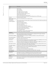
... address, auto-configuration (with configuration file download) Config files can be edited with a network analyzer or RMON probe. Data Sheet Feature IPv6 IPv6 IPv6 QoS Multicast Listener Discovery (MLD) snooping IPv6 applications IPv6 RFCs supported Management Web user interface Remote Monitoring (RMON) IPv4 and IPv6 dual stack Firmware upgrade Port mirroring VLAN mirroring DHCP (Options 66 and 67) Text-editable config files Smartports Cloud services Localization Other management Power Efficiency Energy Detect Cable length detection General Jumbo frames MAC table...
... address, auto-configuration (with configuration file download) Config files can be edited with a network analyzer or RMON probe. Data Sheet Feature IPv6 IPv6 IPv6 QoS Multicast Listener Discovery (MLD) snooping IPv6 applications IPv6 RFCs supported Management Web user interface Remote Monitoring (RMON) IPv4 and IPv6 dual stack Firmware upgrade Port mirroring VLAN mirroring DHCP (Options 66 and 67) Text-editable config files Smartports Cloud services Localization Other management Power Efficiency Energy Detect Cable length detection General Jumbo frames MAC table...

Hardware Installation Guide
Page 3
... xvi Configuration Guides xvi Maintain and Operate Guides xvii Installation and Upgrade Guides xvii Licensing Guide xvii Command References xvii Technical References xvii Error and System Messages xvii Troubleshooting Guide xvii Obtaining Documentation and Submitting a Service Request xviii Using a Fabric Extender with a Cisco Nexus 5000 Series Switch 1-1 Information About Using a Fabric Extender with a Cisco Nexus 5000 Series Switch 1-1 Cisco Nexus 2248TP-E 1-1 Chassis 1-2 Ports 1-3 Power Supplies 1-3 Fan Trays 1-7 Supported Transceivers and Cables 1-9 SFP Transceivers 1-9 SFP+ Copper Cables...
... xvi Configuration Guides xvi Maintain and Operate Guides xvii Installation and Upgrade Guides xvii Licensing Guide xvii Command References xvii Technical References xvii Error and System Messages xvii Troubleshooting Guide xvii Obtaining Documentation and Submitting a Service Request xviii Using a Fabric Extender with a Cisco Nexus 5000 Series Switch 1-1 Information About Using a Fabric Extender with a Cisco Nexus 5000 Series Switch 1-1 Cisco Nexus 2248TP-E 1-1 Chassis 1-2 Ports 1-3 Power Supplies 1-3 Fan Trays 1-7 Supported Transceivers and Cables 1-9 SFP Transceivers 1-9 SFP+ Copper Cables...

Hardware Installation Guide
Page 4
... Cables 1-23 Cisco Nexus 2232PP 1-23 Chassis 1-24 Ports 1-25 Power Supplies 1-25 Fan Trays 1-26 Supported SFP+ Transceivers 1-28 SFP+ Transceivers 1-28 SFP+ Copper Cables 1-28 Cisco Nexus 2224TP 1-29 Chassis 1-29 Ports 1-30 Power Supplies 1-30 Fan Tray 1-31 Supported SFP+ Transceivers 1-32 SFP+ Transceivers 1-32 SFP+ Copper Cables 1-32 Cisco Nexus 2148T 1-33 Features 1-33 Chassis 1-33 Ports 1-35 Power Supplies 1-35 Fan Tray 1-36 Supported SFP Transceivers 1-37 SFP Transceivers 1-37 SFP+ Copper Cables 1-37 2 C H A P T E R Using a Fabric Extender with a Cisco Nexus 7000 Series Switch...
... Cables 1-23 Cisco Nexus 2232PP 1-23 Chassis 1-24 Ports 1-25 Power Supplies 1-25 Fan Trays 1-26 Supported SFP+ Transceivers 1-28 SFP+ Transceivers 1-28 SFP+ Copper Cables 1-28 Cisco Nexus 2224TP 1-29 Chassis 1-29 Ports 1-30 Power Supplies 1-30 Fan Tray 1-31 Supported SFP+ Transceivers 1-32 SFP+ Transceivers 1-32 SFP+ Copper Cables 1-32 Cisco Nexus 2148T 1-33 Features 1-33 Chassis 1-33 Ports 1-35 Power Supplies 1-35 Fan Tray 1-36 Supported SFP Transceivers 1-37 SFP Transceivers 1-37 SFP+ Copper Cables 1-37 2 C H A P T E R Using a Fabric Extender with a Cisco Nexus 7000 Series Switch...
Hardware Installation Guide
Page 16
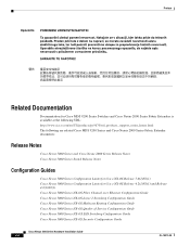
...OS Release 5.0(2)N1(1) Cisco Nexus 5000 Series Configuration Limits for Cisco NX-OS Release 4.2(1)N1(1) and Release 4.2(1)N2(1) Cisco Nexus 5000 Series NX-OS Fibre Channel over Ethernet Configuration Guide Cisco Nexus 5000 Series NX-OS Layer 2 Switching Configuration Guide Cisco Nexus 5000 Series NX-OS Multicast Routing Configuration Guide Cisco Nexus 5000 Series NX-OS Quality of Service Configuration Guide Cisco Nexus 5000 Series NX-OS SAN Switching Configuration Guide Cisco Nexus 5000 Series NX-OS Security Configuration Guide Cisco Nexus 2000 Series Hardware Installation Guide xvi OL-19013...
...OS Release 5.0(2)N1(1) Cisco Nexus 5000 Series Configuration Limits for Cisco NX-OS Release 4.2(1)N1(1) and Release 4.2(1)N2(1) Cisco Nexus 5000 Series NX-OS Fibre Channel over Ethernet Configuration Guide Cisco Nexus 5000 Series NX-OS Layer 2 Switching Configuration Guide Cisco Nexus 5000 Series NX-OS Multicast Routing Configuration Guide Cisco Nexus 5000 Series NX-OS Quality of Service Configuration Guide Cisco Nexus 5000 Series NX-OS SAN Switching Configuration Guide Cisco Nexus 5000 Series NX-OS Security Configuration Guide Cisco Nexus 2000 Series Hardware Installation Guide xvi OL-19013...
Hardware Installation Guide
Page 143
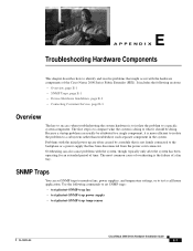
... has been operating for an extended period of overheating is to isolate the problem to a specific system component. Overheating can set SNMP traps: • test pfmtest-SNMP-trap fan • test pfmtest-SNMP-trap power supply • test pfmtest-SNMP-trap temp-sensor OL-19013-05 Cisco Nexus 2000 Series Hardware Installation Guide E-1 Because a startup problem can usually be attributed to a single component, it should be doing to what...
... has been operating for an extended period of overheating is to isolate the problem to a specific system component. Overheating can set SNMP traps: • test pfmtest-SNMP-trap fan • test pfmtest-SNMP-trap power supply • test pfmtest-SNMP-trap temp-sensor OL-19013-05 Cisco Nexus 2000 Series Hardware Installation Guide E-1 Because a startup problem can usually be attributed to a single component, it should be doing to what...
Software Configuration Guide
Page 20
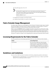
... enter the install all command, it upgrades the software on the parent Cisco Nexus Series switch and also upgrades the software on any attached Fabric Extender. Licensing Requirements for the Fabric Extender The following table shows the licensing requirements for the interfaces on the switch: interface ethernet slot/port • slot identifies the slot number on the Fabric Extender. • port identifies the port number on a specific slot and chassis ID...
... enter the install all command, it upgrades the software on the parent Cisco Nexus Series switch and also upgrades the software on any attached Fabric Extender. Licensing Requirements for the Fabric Extender The following table shows the licensing requirements for the interfaces on the switch: interface ethernet slot/port • slot identifies the slot number on the Fabric Extender. • port identifies the port number on a specific slot and chassis ID...
Software Configuration Guide
Page 23
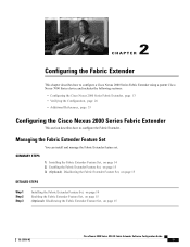
... • Verifying the Configuration, page 26 • Additional References, page 33 Configuring the Cisco Nexus 2000 Series Fabric Extender This section describes how to configure the Fabric Extender. Managing the Fabric Extender Feature Set You can install and manage the Fabric Extender feature set. Installing the Fabric Extender Feature Set, on page 15 OL-25816-02 Cisco Nexus 2000 Series NX-OS Fabric Extender Software Configuration Guide 13
... • Verifying the Configuration, page 26 • Additional References, page 33 Configuring the Cisco Nexus 2000 Series Fabric Extender This section describes how to configure the Fabric Extender. Managing the Fabric Extender Feature Set You can install and manage the Fabric Extender feature set. Installing the Fabric Extender Feature Set, on page 15 OL-25816-02 Cisco Nexus 2000 Series NX-OS Fabric Extender Software Configuration Guide 13

Software Configuration Guide
Page 25
... use the no feature-set fex command might take some time to this command. To disable the Fabric Extender feature set, use the switchto vdc command. Exits configuration mode. Before You Begin Ensure that you have installed the feature set in the default VDC. SUMMARY STEPS 1. Example: switch(config)# exit switch# Disallowing the Fabric Extender Feature Set By default, when you have installed the Fabric Extender feature set in a specific VDC on the device...
... use the no feature-set fex command might take some time to this command. To disable the Fabric Extender feature set, use the switchto vdc command. Exits configuration mode. Before You Begin Ensure that you have installed the feature set in the default VDC. SUMMARY STEPS 1. Example: switch(config)# exit switch# Disallowing the Fabric Extender Feature Set By default, when you have installed the Fabric Extender feature set in a specific VDC on the device...
Software Configuration Guide
Page 26
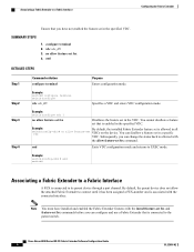
... not allow feature-set is connected to the parent switch. vdc vdc_ID 3. Example: By default, the installed Fabric Extender feature set VDCs on the device. Example: switch# configure terminal switch(config)# vdc vdc_ID Specifies a VDC and enters VDC configuration mode. end Exits VDC configuration mode and returns to its parent device through a port channel. You cannot disallow a feature set in the specified VDC. Cisco Nexus 2000 Series NX-OS Fabric Extender Software Configuration Guide 16 OL...
... not allow feature-set is connected to the parent switch. vdc vdc_ID 3. Example: By default, the installed Fabric Extender feature set VDCs on the device. Example: switch# configure terminal switch(config)# vdc vdc_ID Specifies a VDC and enters VDC configuration mode. end Exits VDC configuration mode and returns to its parent device through a port channel. You cannot disallow a feature set in the specified VDC. Cisco Nexus 2000 Series NX-OS Fabric Extender Software Configuration Guide 16 OL...
Software Configuration Guide
Page 39
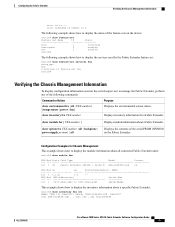
... Software Configuration Guide 29 FEX Mod MAC-Address(es) Serial-Num 101 1 5475.d0a9.4940 to 5475.d0a9.496f JAF1418AARL This example shows how to display the inventory information about a specific Fabric Extender: switch# show inventory fex FEX-number Displays inventory information for Chassis Management This example shows how to manage the Fabric Extender, perform one of the following commands: Command or Action Purpose show feature-set...
... Software Configuration Guide 29 FEX Mod MAC-Address(es) Serial-Num 101 1 5475.d0a9.4940 to 5475.d0a9.496f JAF1418AARL This example shows how to display the inventory information about a specific Fabric Extender: switch# show inventory fex FEX-number Displays inventory information for Chassis Management This example shows how to manage the Fabric Extender, perform one of the following commands: Command or Action Purpose show feature-set...
Configuration Guide
Page 68
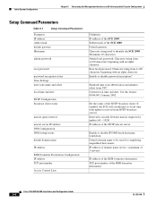
...System Configuration Chapter 5 Connecting the Management Interfaces and Performing Initial System Configuration Setup Command Parameters Table 5-1 Setup Command Parameters Parameter IP address subnet mask default gateway Hostname admin password root password password encryption status Time Settings time zone name and offset local time and date SNTP Configuration broadcast client status unicast query interval unicast server IP address DNS Configuration DNS lookup status default domain name IP address RDR Formatter Destination Configuration IP address TCP port number Access Control Lists...
...System Configuration Chapter 5 Connecting the Management Interfaces and Performing Initial System Configuration Setup Command Parameters Table 5-1 Setup Command Parameters Parameter IP address subnet mask default gateway Hostname admin password root password password encryption status Time Settings time zone name and offset local time and date SNTP Configuration broadcast client status unicast query interval unicast server IP address DNS Configuration DNS lookup status default domain name IP address RDR Formatter Destination Configuration IP address TCP port number Access Control Lists...
Configuration Guide
Page 82
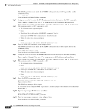
... addresses, and press Enter. Note that there is 20. • To add more entries, type yand press • Enter Would you like to add another SNMP GET community? [no default for this SET community. Enter Access list number allowing access with this community string, use this parameter. Type a number (1 through 99) or type "0" to permit access to configure SNMP trap managers? [no default for this parameter. 5-18 Cisco SCE 2000 4xGBE Installation and Configuration Guide...
... addresses, and press Enter. Note that there is 20. • To add more entries, type yand press • Enter Would you like to add another SNMP GET community? [no default for this SET community. Enter Access list number allowing access with this community string, use this parameter. Type a number (1 through 99) or type "0" to permit access to configure SNMP trap managers? [no default for this parameter. 5-18 Cisco SCE 2000 4xGBE Installation and Configuration Guide...
Configuration Guide
Page 110
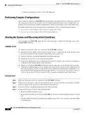
... system and interface configuration, refer to start up , and performed the initial system configuration, you have installed your SCE 2000 platform and connecting cables, complete the following LEDs: • Both Power LEDs should be green. • Bypass LED should be green while the SCE 2000 is flashing green. During the boot process, observe the following steps to the following documents: • Cisco Service Control Engine (SCE) Software Configuration Guide • Cisco Service Control Engine (SCE) CLI Command Reference Starting the System...
... system and interface configuration, refer to start up , and performed the initial system configuration, you have installed your SCE 2000 platform and connecting cables, complete the following LEDs: • Both Power LEDs should be green. • Bypass LED should be green while the SCE 2000 is flashing green. During the boot process, observe the following steps to the following documents: • Cisco Service Control Engine (SCE) Software Configuration Guide • Cisco Service Control Engine (SCE) CLI Command Reference Starting the System...
Configuration Guide
Page 113
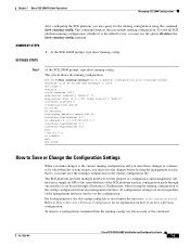
... configuration. The SCE platform provides multiple interfaces for the purpose of the command. To view all configuration settings are saved regardless of the management interface used to Recover a Previous Configuration for an explanation on 15:50:56 CET MON December 11 2005 #cli-type 1 #version 1 clock timezone CET 1 snmp-server community "public" ro snmp-server host 10.1.1.253 traps version 1 "public" interface LineCard 0 connection-mode active no silent no shutdown flow-aging default...
... configuration. The SCE platform provides multiple interfaces for the purpose of the command. To view all configuration settings are saved regardless of the management interface used to Recover a Previous Configuration for an explanation on 15:50:56 CET MON December 11 2005 #cli-type 1 #version 1 clock timezone CET 1 snmp-server community "public" ro snmp-server host 10.1.1.253 traps version 1 "public" interface LineCard 0 connection-mode active no silent no shutdown flow-aging default...
Configuration Guide
Page 122
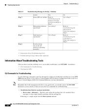
... you can enter CLI commands for Startup Problems Action Yes Status LED red (failure) Refer to Troubleshooting the Firmware Package Installation and go to successfully troubleshoot your SCE 2000 platform. Following is not operational, you should connect the SCE 2000 platform to be installed. Management interface Go to Step 6 System startup - Refer to Cisco Service Control Engine (SCE) Software Configuration Guide or the Cisco Service Control Engine (SCE) CLI Command Reference for Troubleshooting Use the following commands to provide information...
... you can enter CLI commands for Startup Problems Action Yes Status LED red (failure) Refer to Troubleshooting the Firmware Package Installation and go to successfully troubleshoot your SCE 2000 platform. Following is not operational, you should connect the SCE 2000 platform to be installed. Management interface Go to Step 6 System startup - Refer to Cisco Service Control Engine (SCE) Software Configuration Guide or the Cisco Service Control Engine (SCE) CLI Command Reference for Troubleshooting Use the following commands to provide information...
Configuration Guide
Page 129
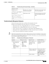
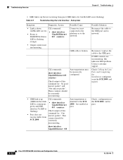
... header Returned error is: The file is not a software installation package file. /tffs0/ device is broken. Table 8-6 Troubleshooting the Management Subsystem Symptom Diagnostic Action Management link down and/or a Telnet connection cannot be any of the following to solve the problem and then reconnect through the management port. OL-7824-06 Cisco SCE 2000 4xGBE Installation and Configuration Guide 8-9 Cable not connected to network. Interface Mng {0/1 | 0/2} active-port Check / Replace the cable. Possible Solution Reconnect the cable to the...
... header Returned error is: The file is not a software installation package file. /tffs0/ device is broken. Table 8-6 Troubleshooting the Management Subsystem Symptom Diagnostic Action Management link down and/or a Telnet connection cannot be any of the following to solve the problem and then reconnect through the management port. OL-7824-06 Cisco SCE 2000 4xGBE Installation and Configuration Guide 8-9 Cable not connected to network. Interface Mng {0/1 | 0/2} active-port Check / Replace the cable. Possible Solution Reconnect the cable to the...
Configuration Guide
Page 132
... lit, but Rx LED is not flashing) Table 8-7 Troubleshooting the Link Interface Subsystem Symptom Diagnostic Action • Link is disabled at the SCE 2000 but enabled at peer. Check Cabling the Line Ports and Completing the Installation configurati on in the SCE 2000 and in peer. 8-12 Cisco SCE 2000 4xGBE Installation and Configuration Guide OL-7824-06 Possible Cause Connector is broken. Check output of this command for : "In...
... lit, but Rx LED is not flashing) Table 8-7 Troubleshooting the Link Interface Subsystem Symptom Diagnostic Action • Link is disabled at the SCE 2000 but enabled at peer. Check Cabling the Line Ports and Completing the Installation configurati on in the SCE 2000 and in peer. 8-12 Cisco SCE 2000 4xGBE Installation and Configuration Guide OL-7824-06 Possible Cause Connector is broken. Check output of this command for : "In...


