
Administration Guide
Page 2
... Actions 12 Using the Switch Main Menu 13 System Configuration 13 System Information 14 Management Settings 16 Username & Password Settings 21 Security Settings 22 VLAN Management 25 IP Configuration 26 File Management 40 Restore System Default Settings 43 Reset to Factory Settings 43 Reboot System 43 Stack Configuration 44 Port Status 44 SGE2010/SGE2010P Administration Guide i
... Actions 12 Using the Switch Main Menu 13 System Configuration 13 System Information 14 Management Settings 16 Username & Password Settings 21 Security Settings 22 VLAN Management 25 IP Configuration 26 File Management 40 Restore System Default Settings 43 Reset to Factory Settings 43 Reboot System 43 Stack Configuration 44 Port Status 44 SGE2010/SGE2010P Administration Guide i

Administration Guide
Page 3
... Configuration 46 Port Settings 46 PoE Settings 47 System Mode (Layer 2 / Layer 3) Selection 48 Help 49 Logout 50 5 Web Utility Configuration 51 Connecting to the Switch with the Web-Based Utility 51 Using Menus in the Web-Based Utility 51 Viewing On-line Help 52 A Contacts 53 US/Canada Contacts 53... Obtaining Warranty Service 57 Technical Support 57 D Federal Communication Commission Interference Statement . . 58 Industry Canada Statement 58 EC Declaration of Conformity (Europe) 58 E Specifications 59 SGE2010/SGE2010P Administration Guide ii
... Configuration 46 Port Settings 46 PoE Settings 47 System Mode (Layer 2 / Layer 3) Selection 48 Help 49 Logout 50 5 Web Utility Configuration 51 Connecting to the Switch with the Web-Based Utility 51 Using Menus in the Web-Based Utility 51 Viewing On-line Help 52 A Contacts 53 US/Canada Contacts 53... Obtaining Warranty Service 57 Technical Support 57 D Federal Communication Commission Interference Statement . . 58 Industry Canada Statement 58 EC Declaration of Conformity (Europe) 58 E Specifications 59 SGE2010/SGE2010P Administration Guide ii

Administration Guide
Page 4
... and back panels of the Switch. Introduction Welcome Thank you need to manage your different networks. 1 Introduction What's in this User Guide? These instructions should be all you for setting up , and configure it easy to get the most out of the switch. • Chapter 3, "Connecting Devices to the SGE2010/SGE2010P" This chapter explains how...
... and back panels of the Switch. Introduction Welcome Thank you need to manage your different networks. 1 Introduction What's in this User Guide? These instructions should be all you for setting up , and configure it easy to get the most out of the switch. • Chapter 3, "Connecting Devices to the SGE2010/SGE2010P" This chapter explains how...

Administration Guide
Page 5
... used to supply power to various Linksys products over that port. The SGE2010 and SGE2010P are listed below. These functions are 48-port, layer-2 Ethernet switches that affordably expand the capability of numerous functions. 2 Getting to Know the SGE2010/SGE2010P Getting to Know the SGE2010/SGE2010P This chapter describes the ports, LEDs, and other features on that...
... used to supply power to various Linksys products over that port. The SGE2010 and SGE2010P are listed below. These functions are 48-port, layer-2 Ethernet switches that affordably expand the capability of numerous functions. 2 Getting to Know the SGE2010/SGE2010P Getting to Know the SGE2010/SGE2010P This chapter describes the ports, LEDs, and other features on that...

Administration Guide
Page 6
... with 48 auto-sensing, Ethernet (802.3) network ports, which use as stacking ports. Redundant Power Supply (Linksys RPS1000) SGE2010/SGE2010P Administration Guide 3 The switch provides four mini-GBIC ports. The MGBSX1 and the MGBLH1 require fiber cabling with LC connectors, while the MGBT1 requires a... Category 5e Ethernet cable with the switch. Getting to Know the SGE2010/SGE2010P Feature 1-48 miniGBIC1-4 Description The Switch is in half and full-duplex modes. The Fast Ethernet ports support network speeds of 15.4W ...
... with 48 auto-sensing, Ethernet (802.3) network ports, which use as stacking ports. Redundant Power Supply (Linksys RPS1000) SGE2010/SGE2010P Administration Guide 3 The switch provides four mini-GBIC ports. The MGBSX1 and the MGBLH1 require fiber cabling with LC connectors, while the MGBT1 requires a... Category 5e Ethernet cable with the switch. Getting to Know the SGE2010/SGE2010P Feature 1-48 miniGBIC1-4 Description The Switch is in half and full-duplex modes. The Fast Ethernet ports support network speeds of 15.4W ...

Administration Guide
Page 7
... connect your network devices, make sure you connect your network devices to 100 meters (328 feet). SGE2010/SGE2010P Administration Guide 4 A 10Mbps hub connected to another 10Mbps hub can span up to the switch. • "Sample Network Configuration," on page 4 • "Maximum Cabling Distances," on page ... hubs. Maximum Cabling Distances When you don't exceed the maximum cabling distances, which are listed in the following table: From Switch Hub Switch or Hub To Switch or Hub* Hub Computer Maximum Distance 100 meters (328 feet) 5 meters (16.4 feet) 100 meters (328 feet)...
... connect your network devices, make sure you connect your network devices to 100 meters (328 feet). SGE2010/SGE2010P Administration Guide 4 A 10Mbps hub connected to another 10Mbps hub can span up to the switch. • "Sample Network Configuration," on page 4 • "Maximum Cabling Distances," on page ... hubs. Maximum Cabling Distances When you don't exceed the maximum cabling distances, which are listed in the following table: From Switch Hub Switch or Hub To Switch or Hub* Hub Computer Maximum Distance 100 meters (328 feet) 5 meters (16.4 feet) 100 meters (328 feet)...
Administration Guide
Page 8
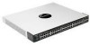
...minimum clearance of two inches (50 mm). • Connect the supplied power cord to the recessed areas on a wall with the switch. NOTE: The four supplied mounting brackets can be easily connected. • Keep cabling away from water and moisture sources. •...; To ensure adequate air flow around the switch, be accessible and that is supplied with the wallmount brackets provided. Place the Ethernet switch on a desktop near an AC power source. Desktop Placement 1. SGE2010/SGE2010P Administration Guide 5 Placement Options Before connecting cables to the...
...minimum clearance of two inches (50 mm). • Connect the supplied power cord to the recessed areas on a wall with the switch. NOTE: The four supplied mounting brackets can be easily connected. • Keep cabling away from water and moisture sources. •...; To ensure adequate air flow around the switch, be accessible and that is supplied with the wallmount brackets provided. Place the Ethernet switch on a desktop near an AC power source. Desktop Placement 1. SGE2010/SGE2010P Administration Guide 5 Placement Options Before connecting cables to the...

Administration Guide
Page 9
...wide, (each Ethernet switch requires 1RU of the Ethernet switch. 5. SGE2010/SGE2010P Administration Guide 6 Rack-Mount Placement To mount the Ethernet switch in the rack), follow these instructions: 1. Remove the four front screws on the side of the Ethernet switch. Place one of the...the screws for the Ethernet switch so it does not exceed the environmental restrictions mentioned in step 1). 4. Attach the Ethernet switch to the spacer and reinstall the four screws (removed in the specifications. Connecting Devices to the SGE2010/SGE2010P Placement Options CAUTION: Keep ...
...wide, (each Ethernet switch requires 1RU of the Ethernet switch. 5. SGE2010/SGE2010P Administration Guide 6 Rack-Mount Placement To mount the Ethernet switch in the rack), follow these instructions: 1. Remove the four front screws on the side of the Ethernet switch. Place one of the...the screws for the Ethernet switch so it does not exceed the environmental restrictions mentioned in step 1). 4. Attach the Ethernet switch to the spacer and reinstall the four screws (removed in the specifications. Connecting Devices to the SGE2010/SGE2010P Placement Options CAUTION: Keep ...

Administration Guide
Page 10
... to one of the supplied spacers on the Ethernet switch. Connect the other end to a PC or other corners of the Ethernet switch so the four holes align to a wall with the ports located on the Ethernet switch. SGE2010/SGE2010P Administration Guide 7 Place one of the uplink ports... on the side of the Ethernet switch. 5. CAUTION: Ensure that the Ethernet switch is mounted to the spacer and reinstall the four screws (removed in any ...
... to one of the supplied spacers on the Ethernet switch. Connect the other end to a PC or other corners of the Ethernet switch so the four holes align to a wall with the ports located on the Ethernet switch. SGE2010/SGE2010P Administration Guide 7 Place one of the uplink ports... on the side of the Ethernet switch. 5. CAUTION: Ensure that the Ethernet switch is mounted to the spacer and reinstall the four screws (removed in any ...

Administration Guide
Page 11
.... Proceed as HyperTerminal.) 6. Connect the supplied power cord to the power port, and plug the other end to "Web Utility Configuration" section on the Ethernet switch. SGE2010/SGE2010P Administration Guide 8 Each active port's corresponding Act/Link LED will also light up on page 50. If a port has an active Gigabit connection, then its...
.... Proceed as HyperTerminal.) 6. Connect the supplied power cord to the power port, and plug the other end to "Web Utility Configuration" section on the Ethernet switch. SGE2010/SGE2010P Administration Guide 8 Each active port's corresponding Act/Link LED will also light up on page 50. If a port has an active Gigabit connection, then its...

Administration Guide
Page 12
.... • "Connecting to Your Switch with HyperTerminal," on page 9 • "Connecting to the Switch with Telnet," on page 12 &#... Selecting Menu Options and Actions (see page 12) • Using the Switch Main Menu (see page 13) • System Configuration (see page 13)...Switch with a blank password. The switch features a menu-driven console interface for the first time, you connect to the switch IP address 192.168.1.254. SGE2010/SGE2010P...switch. 4 Using the Console Connecting to Your Switch with HyperTerminal Using the Console This chapter describes the use of the switch...
.... • "Connecting to Your Switch with HyperTerminal," on page 9 • "Connecting to the Switch with Telnet," on page 12 &#... Selecting Menu Options and Actions (see page 12) • Using the Switch Main Menu (see page 13) • System Configuration (see page 13)...Switch with a blank password. The switch features a menu-driven console interface for the first time, you connect to the switch IP address 192.168.1.254. SGE2010/SGE2010P...switch. 4 Using the Console Connecting to Your Switch with HyperTerminal Using the Console This chapter describes the use of the switch...

Administration Guide
Page 13
Click the Start button. Choose Programs > Accessories > Communications > HyperTerminal. 2. SGE2010/SGE2010P Administration Guide 10 On the Connection Description screen, type a name for this connection, select an icon, and then click OK. 3. On the Connect To screen, use the Connect using drop-down list to select a port to Your Switch with the switch: COMn, or TCP/ IP. Using the Console Connecting to communicate with HyperTerminal 1.
Click the Start button. Choose Programs > Accessories > Communications > HyperTerminal. 2. SGE2010/SGE2010P Administration Guide 10 On the Connection Description screen, type a name for this connection, select an icon, and then click OK. 3. On the Connect To screen, use the Connect using drop-down list to select a port to Your Switch with the switch: COMn, or TCP/ IP. Using the Console Connecting to communicate with HyperTerminal 1.

Administration Guide
Page 14
Optionally, on the File menu, click Save to Your Switch with HyperTerminal 4. SGE2010/SGE2010P Administration Guide 11 Then, click the OK button. 6. Set the serial port settings as follows: • Bits per second: 115200 • Data bits: 8 • Parity: None • Stop bits: 1 • Flow control: None 5. Using the Console Connecting to save these settings. The next time that you need to connect to the console, you can open this saved connection.
Optionally, on the File menu, click Save to Your Switch with HyperTerminal 4. SGE2010/SGE2010P Administration Guide 11 Then, click the OK button. 6. Set the serial port settings as follows: • Bits per second: 115200 • Data bits: 8 • Parity: None • Stop bits: 1 • Flow control: None 5. Using the Console Connecting to save these settings. The next time that you need to connect to the console, you can open this saved connection.

Administration Guide
Page 15
... the Esc key to return to set passwords for other users. Logging On to login, enter the default login and password: admin The Switch Main Menu appears. Selecting Menu Options and Actions Within the Console Interface, menus list options in the User Name field. Move the cursor from... to the next on your keyboard: Key Arrow keys Number key Tab Enter Esc Function Move the cursor up, down, left, or right. SGE2010/SGE2010P Administration Guide 12 Open a command line editor and enter telnet . Start HyperTerminal and open the connection that is highlighted by the cursor. Actions ...
... the Esc key to return to set passwords for other users. Logging On to login, enter the default login and password: admin The Switch Main Menu appears. Selecting Menu Options and Actions Within the Console Interface, menus list options in the User Name field. Move the cursor from... to the next on your keyboard: Key Arrow keys Number key Tab Enter Esc Function Move the cursor up, down, left, or right. SGE2010/SGE2010P Administration Guide 12 Open a command line editor and enter telnet . Start HyperTerminal and open the connection that is highlighted by the cursor. Actions ...

Administration Guide
Page 16
... settings, and download upgrade files. System Information (see page 16) SGE2010/SGE2010P Administration Guide 13 Management Settings (see page 14) 2. Using the Console Using the Switch Main Menu Using the Switch Main Menu The Switch Main Menu provides access to screens that you can use this menu ...if you need to restore default settings, reset the switch to screens where you can manage system information, view or modify management settings, set up user accounts, and manage security settings. Port Configuration (see page 44) 3. Port Status (see page 46...
... settings, and download upgrade files. System Information (see page 16) SGE2010/SGE2010P Administration Guide 13 Management Settings (see page 14) 2. Using the Console Using the Switch Main Menu Using the Switch Main Menu The Switch Main Menu provides access to screens that you can use this menu ...if you need to restore default settings, reset the switch to screens where you can manage system information, view or modify management settings, set up user accounts, and manage security settings. Port Configuration (see page 44) 3. Port Status (see page 46...

Administration Guide
Page 17
...menu provides access to Factory Settings (see page 43) 10. Back. Security Settings (see page 40) 8. System Configuration. 2. VLAN Management (see page 43) 9. Restore System Default Settings (see page 25) 6. Stack Configuration (see page 15) 0.Back (Select to ... 3. When you can view firmware version information and general system information. 1. SGE2010/SGE2010P Administration Guide 14 Username & Password Settings (see page 26) 7. IP Configuration (see page 21) 4. From the Switch Main Menu, select 1. System Information. 3. Reset to screens where you are...
...menu provides access to Factory Settings (see page 43) 10. Back. Security Settings (see page 40) 8. System Configuration. 2. VLAN Management (see page 43) 9. Restore System Default Settings (see page 25) 6. Stack Configuration (see page 15) 0.Back (Select to ... 3. When you can view firmware version information and general system information. 1. SGE2010/SGE2010P Administration Guide 14 Username & Password Settings (see page 26) 7. IP Configuration (see page 21) 4. From the Switch Main Menu, select 1. System Information. 3. Reset to screens where you are...
Administration Guide
Page 18
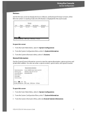
... Menu, select 1. You also can enter a system contact, system name, and system location. From the Switch Main Menu, select 1. In stacking mode, this screen: 1. To open this screen: 1. System Configuration. 2. System Information. 3. To open ...and system MAC address. General Information Use the General System Information screen to display the boot, software, and hardware firmware versions of the Ethernet switch. From the System Configuration Menu, select 1. From the System Information Menu, select 2. General System Information. From the System Configuration Menu, select ...
... Menu, select 1. You also can enter a system contact, system name, and system location. From the Switch Main Menu, select 1. In stacking mode, this screen: 1. To open this screen: 1. System Configuration. 2. System Information. 3. To open ...and system MAC address. General Information Use the General System Information screen to display the boot, software, and hardware firmware versions of the Ethernet switch. From the System Configuration Menu, select 1. From the System Information Menu, select 2. General System Information. From the System Configuration Menu, select ...

Administration Guide
Page 19
... where you can change the system contact, system name, and location: 1. System Configuration Menu. 2. SGE2010/SGE2010P Administration Guide 16 Telnet Configuration (see page 17) 2. From the Switch Main Menu, select 1. Select Edit, and then make your changes. 4. Management Settings The Management Settings screen provides access to the next. 2. Press the Tab key to move the...
... where you can change the system contact, system name, and location: 1. System Configuration Menu. 2. SGE2010/SGE2010P Administration Guide 16 Telnet Configuration (see page 17) 2. From the Switch Main Menu, select 1. Select Edit, and then make your changes. 4. Management Settings The Management Settings screen provides access to the next. 2. Press the Tab key to move the...

Administration Guide
Page 20
...complete message appears, press the Esc key to move the cursor to the Action list. To open this screen: 1. Management Settings. 3. To change the baud rate of the serial port: 1. Select Edit, and then make changes. 2. ...From the System Configuration Menu, select 2. Serial Port Configuration. System Configuration Menu. 2. From the Switch Main Menu, select 1. Telnet Configuration Use the Telnet Configuration screen to save your changes. 4. Select Save to view ...or change the baud rate of the Ethernet switch. SGE2010/SGE2010P Administration Guide 17
...complete message appears, press the Esc key to move the cursor to the Action list. To open this screen: 1. Management Settings. 3. To change the baud rate of the serial port: 1. Select Edit, and then make changes. 2. ...From the System Configuration Menu, select 2. Serial Port Configuration. System Configuration Menu. 2. From the Switch Main Menu, select 1. Telnet Configuration Use the Telnet Configuration screen to save your changes. 4. Select Save to view ...or change the baud rate of the Ethernet switch. SGE2010/SGE2010P Administration Guide 17

Administration Guide
Page 21
... Esc key to move the cursor to the Action list. From the Switch Main Menu, select 1. From the System Configuration Menu, select 2. SSH Crypto Key Generation (see page 19) 2. From the Management Settings Menu, choose 3. SGE2010/SGE2010P Administration Guide 18 From the Switch Main Menu, select 1. Select Save to the Action list. 3. Select Edit, and...
... Esc key to move the cursor to the Action list. From the Switch Main Menu, select 1. From the System Configuration Menu, select 2. SSH Crypto Key Generation (see page 19) 2. From the Management Settings Menu, choose 3. SGE2010/SGE2010P Administration Guide 18 From the Switch Main Menu, select 1. Select Save to the Action list. 3. Select Edit, and...
