
Administration Guide
Page 2
...? 1 2 Getting to Know the SGE2010/SGE2010P 2 SGE2010/P Front Panel 2 SGE2010/P Back Panel 3 3 Connecting Devices to the SGE2010/SGE2010P 4 Sample Network Configuration 4 Maximum Cabling Distances 4 Before You Install the Switch... 5 Placement Options 5 Desktop Placement 5 Rack-Mount Placement 6 Wall-Mount Placement 7 Connecting the Cables 7 4 Using the Console 9 Connecting to Your Switch with HyperTerminal 9 Connecting to the Switch with Telnet 12 Logging On...
...? 1 2 Getting to Know the SGE2010/SGE2010P 2 SGE2010/P Front Panel 2 SGE2010/P Back Panel 3 3 Connecting Devices to the SGE2010/SGE2010P 4 Sample Network Configuration 4 Maximum Cabling Distances 4 Before You Install the Switch... 5 Placement Options 5 Desktop Placement 5 Rack-Mount Placement 6 Wall-Mount Placement 7 Connecting the Cables 7 4 Using the Console 9 Connecting to Your Switch with HyperTerminal 9 Connecting to the Switch with Telnet 12 Logging On...

Administration Guide
Page 6
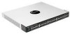
..., refer to the SFE2010/SGE2010 Reference Guide. The switch can connect a serial cable to a PC's serial port for a mini-GBIC expansion module, so the Switch can operate in stacking mode by default. The switch provides four mini-GBIC ports. Redundant Power Supply (Linksys RPS1000) SGE2010/SGE2010P Administration Guide 3 SGE2010/P Back Panel Feature Power Console RPS Description The Power...
..., refer to the SFE2010/SGE2010 Reference Guide. The switch can connect a serial cable to a PC's serial port for a mini-GBIC expansion module, so the Switch can operate in stacking mode by default. The switch provides four mini-GBIC ports. Redundant Power Supply (Linksys RPS1000) SGE2010/SGE2010P Administration Guide 3 SGE2010/P Back Panel Feature Power Console RPS Description The Power...

Administration Guide
Page 11
... Devices to the SGE2010/SGE2010P Connecting the Cables CAUTION: Observe the orientation of a different power cord could damage the Ethernet switch. 7. Use of the mini-GBIC module before inserting it into an electrical outlet. If you use the console interface to configure the Ethernet switch, then connect the supplied serial cable to the console port (located on...
... Devices to the SGE2010/SGE2010P Connecting the Cables CAUTION: Observe the orientation of a different power cord could damage the Ethernet switch. 7. Use of the mini-GBIC module before inserting it into an electrical outlet. If you use the console interface to configure the Ethernet switch, then connect the supplied serial cable to the console port (located on...

Administration Guide
Page 62
...Specifications Model Ports Cabling Type Switching Capacity Forwarding Capacity LEDs Stack Operation Buttons Layer 2 options Layer 3 options • SGE2010 48-port 10/100/1000 Ethernet Switch • SGE2010P 48-port 10/100/1000 Ethernet Switch with PoE •... connectors for 10BASE-T/100BASE-TX/1000Base-T with 4 Gigabit combo ports shared between mini-GBIC ports Console port Auto MDI/MDI-X Autonegotiate/Manual setting RPS port for connecting to Redundant Power Supply unit ...-based VLANs Protocol-based VLAN Management VLAN Multicast TV VLAN Private VLAN Edge (PVE) GVRP Head of layer 3 traffic...
...Specifications Model Ports Cabling Type Switching Capacity Forwarding Capacity LEDs Stack Operation Buttons Layer 2 options Layer 3 options • SGE2010 48-port 10/100/1000 Ethernet Switch • SGE2010P 48-port 10/100/1000 Ethernet Switch with PoE •... connectors for 10BASE-T/100BASE-TX/1000Base-T with 4 Gigabit combo ports shared between mini-GBIC ports Console port Auto MDI/MDI-X Autonegotiate/Manual setting RPS port for connecting to Redundant Power Supply unit ...-based VLANs Protocol-based VLAN Management VLAN Multicast TV VLAN Private VLAN Edge (PVE) GVRP Head of layer 3 traffic...

