
Administration Guide
Page 2
...1 What's in this User Guide? 1 2 Getting to Know the SGE2010/SGE2010P 2 SGE2010/P Front Panel 2 SGE2010/P Back Panel 3 3 Connecting Devices to the SGE2010/SGE2010P 4 Sample Network Configuration 4 Maximum Cabling Distances 4 Before You Install the Switch... 5 Placement Options 5 Desktop Placement 5 Rack-Mount Placement 6 Wall... 12 Using the Switch Main Menu 13 System Configuration 13 System Information 14 Management Settings 16 Username & Password Settings 21 Security Settings 22 VLAN Management 25 IP Configuration 26 File Management 40 Restore System ...
...1 What's in this User Guide? 1 2 Getting to Know the SGE2010/SGE2010P 2 SGE2010/P Front Panel 2 SGE2010/P Back Panel 3 3 Connecting Devices to the SGE2010/SGE2010P 4 Sample Network Configuration 4 Maximum Cabling Distances 4 Before You Install the Switch... 5 Placement Options 5 Desktop Placement 5 Rack-Mount Placement 6 Wall... 12 Using the Switch Main Menu 13 System Configuration 13 System Information 14 Management Settings 16 Username & Password Settings 21 Security Settings 22 VLAN Management 25 IP Configuration 26 File Management 40 Restore System ...

Administration Guide
Page 3
... Configuration 46 Port Settings 46 PoE Settings 47 System Mode (Layer 2 / Layer 3) Selection 48 Help 49 Logout 50 5 Web Utility Configuration 51 Connecting to the Switch with the Web-Based Utility 51 Using Menus in the Web-Based Utility 51 Viewing On-line Help 52 A Contacts 53 US/Canada Contacts 53... Obtaining Warranty Service 57 Technical Support 57 D Federal Communication Commission Interference Statement . . 58 Industry Canada Statement 58 EC Declaration of Conformity (Europe) 58 E Specifications 59 SGE2010/SGE2010P Administration Guide ii
... Configuration 46 Port Settings 46 PoE Settings 47 System Mode (Layer 2 / Layer 3) Selection 48 Help 49 Logout 50 5 Web Utility Configuration 51 Connecting to the Switch with the Web-Based Utility 51 Using Menus in the Web-Based Utility 51 Viewing On-line Help 52 A Contacts 53 US/Canada Contacts 53... Obtaining Warranty Service 57 Technical Support 57 D Federal Communication Commission Interference Statement . . 58 Industry Canada Statement 58 EC Declaration of Conformity (Europe) 58 E Specifications 59 SGE2010/SGE2010P Administration Guide ii

Administration Guide
Page 4
... to other features on the front and back panels of the switch. • Chapter 3, "Connecting Devices to the SGE2010/SGE2010P" This chapter explains how to physically connect your network devices to the switch. • Chapter 4, "Using the Console" This chapter describes...a Linksys Switch. This new Linksys rack mount Switch delivers non-blocking, wire speed switching for your different networks. Introduction Welcome Thank you can use of the switch console, which allows you need to manage your Switch. 1 Introduction What's in this User Guide? The Switch features monitoring ...
... to other features on the front and back panels of the switch. • Chapter 3, "Connecting Devices to the SGE2010/SGE2010P" This chapter explains how to physically connect your network devices to the switch. • Chapter 4, "Using the Console" This chapter describes...a Linksys Switch. This new Linksys rack mount Switch delivers non-blocking, wire speed switching for your different networks. Introduction Welcome Thank you can use of the switch console, which allows you need to manage your Switch. 1 Introduction What's in this User Guide? The Switch features monitoring ...

Administration Guide
Page 5
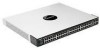
...SGE2010P, a green PoE LED indicates that PoE is actively sending or receiving data over that this Switch is a stack master. 2 Getting to Know the SGE2010/SGE2010P Getting to Know the SGE2010/SGE2010P This chapter describes the ports, LEDs, and other features on the front and back panels of... device. The Act (Activity) LEDs flash to its stack ID. SGE2010/SGE2010P Administration Guide 2 All customized user settings will reset to indicate that the cooling fan is pressed for more than 10 seconds, the Switch will be reset by inserting a pin or paper clip into the RESET...
...SGE2010P, a green PoE LED indicates that PoE is actively sending or receiving data over that this Switch is a stack master. 2 Getting to Know the SGE2010/SGE2010P Getting to Know the SGE2010/SGE2010P This chapter describes the ports, LEDs, and other features on the front and back panels of... device. The Act (Activity) LEDs flash to its stack ID. SGE2010/SGE2010P Administration Guide 2 All customized user settings will reset to indicate that the cooling fan is pressed for more than 10 seconds, the Switch will be reset by inserting a pin or paper clip into the RESET...

Administration Guide
Page 6
... point for more information about stacking, refer to the SFE2010/SGE2010 Reference Guide. SGE2010/P Back Panel Feature Power Console RPS Description The Power port is where you can be uplinked via fiber to another switch. Use the Linksys MGBT1, MGBSX1, or MGBLH1 mini-GBIC modules...4: Using the Console Interface for Configuration for a mini-GBIC expansion module, so the Switch can connect a serial cable to a PoE port. Getting to Know the SGE2010/SGE2010P Feature 1-48 miniGBIC1-4 Description The Switch is equipped with 48 auto-sensing, Ethernet (802.3) network ports, which use as...
... point for more information about stacking, refer to the SFE2010/SGE2010 Reference Guide. SGE2010/P Back Panel Feature Power Console RPS Description The Power port is where you can be uplinked via fiber to another switch. Use the Linksys MGBT1, MGBSX1, or MGBLH1 mini-GBIC modules...4: Using the Console Interface for Configuration for a mini-GBIC expansion module, so the Switch can connect a serial cable to a PoE port. Getting to Know the SGE2010/SGE2010P Feature 1-48 miniGBIC1-4 Description The Switch is equipped with 48 auto-sensing, Ethernet (802.3) network ports, which use as...

Administration Guide
Page 7
... Administration Guide 4 3 Connecting Devices to the SGE2010/SGE2010P Sample Network Configuration Connecting Devices to the SGE2010/ SGE2010P This chapter explains how to physically connect your network devices, make sure you connect your network devices to the switch. • "Sample Network Configuration," on page 4 • "Maximum Cabling Distances," on page 4 • "Before You Install...
... Administration Guide 4 3 Connecting Devices to the SGE2010/SGE2010P Sample Network Configuration Connecting Devices to the SGE2010/ SGE2010P This chapter explains how to physically connect your network devices, make sure you connect your network devices to the switch. • "Sample Network Configuration," on page 4 • "Maximum Cabling Distances," on page 4 • "Before You Install...
Administration Guide
Page 8
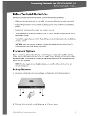
... ensure adequate air flow around the switch, be accessible and that is supplied with the wallmount brackets provided. Place the Ethernet switch on a desktop near an AC power source. Desktop Placement 1. Connecting Devices to the recessed areas on the bottom of a different power cord could damage the switch. SGE2010/SGE2010P Administration Guide 5 Attach the...
... ensure adequate air flow around the switch, be accessible and that is supplied with the wallmount brackets provided. Place the Ethernet switch on a desktop near an AC power source. Desktop Placement 1. Connecting Devices to the recessed areas on the bottom of a different power cord could damage the switch. SGE2010/SGE2010P Administration Guide 5 Attach the...

Administration Guide
Page 9
... supplied spacers on one side of the Ethernet switch. 5. SGE2010/SGE2010P Administration Guide 6 Retain the screws for the other side of the Ethernet switch. Repeat steps 2 through 3 for reinstallation. 2. Attach the Ethernet switch to the SGE2010/SGE2010P Placement Options CAUTION: Keep enough ventilation space for the Ethernet switch so it does not exceed the environmental restrictions...
... supplied spacers on one side of the Ethernet switch. 5. SGE2010/SGE2010P Administration Guide 6 Retain the screws for the other side of the Ethernet switch. Repeat steps 2 through 3 for reinstallation. 2. Attach the Ethernet switch to the SGE2010/SGE2010P Placement Options CAUTION: Keep enough ventilation space for the Ethernet switch so it does not exceed the environmental restrictions...

Administration Guide
Page 10
...to the documentation supplied with appropriate screws (not supplied). Place one of the Ethernet switch. 5. NOTE: If connecting an Ethernet switch to an SVR3000 router, connect it to the SGE2010/SGE2010P Connecting the Cables Wall-Mount Placement 1. For detailed instructions, refer to the ...wall. CAUTION: Ensure that the Ethernet switch is mounted with the ports located on the Ethernet switch. Connecting the Cables To connect network ...
...to the documentation supplied with appropriate screws (not supplied). Place one of the Ethernet switch. 5. NOTE: If connecting an Ethernet switch to an SVR3000 router, connect it to the SGE2010/SGE2010P Connecting the Cables Wall-Mount Placement 1. For detailed instructions, refer to the ...wall. CAUTION: Ensure that the Ethernet switch is mounted with the ports located on the Ethernet switch. Connecting the Cables To connect network ...

Administration Guide
Page 11
...the console interface to configure the Ethernet switch, then connect the supplied serial cable to the console port (located on page 50. SGE2010/SGE2010P Administration Guide 8 The bottom mini-GBIC ports are upside down in relation to the SGE2010/SGE2010P Connecting the Cables CAUTION: Observe ...the orientation of the mini-GBIC module before inserting it into an electrical outlet. Connecting Devices to the top mini-GBIC ports. 5. Use of the Ethernet switch), and tighten the captive retaining...
...the console interface to configure the Ethernet switch, then connect the supplied serial cable to the console port (located on page 50. SGE2010/SGE2010P Administration Guide 8 The bottom mini-GBIC ports are upside down in relation to the SGE2010/SGE2010P Connecting the Cables CAUTION: Observe ...the orientation of the mini-GBIC module before inserting it into an electrical outlet. Connecting Devices to the top mini-GBIC ports. 5. Use of the Ethernet switch), and tighten the captive retaining...

Administration Guide
Page 12
... the use the HyperTerminal to connect to your switch. The switch features a menu-driven console interface for the first time, you to the switch IP address 192.168.1.254. SGE2010/SGE2010P Administration Guide 9 NOTE: The switch also can also be configured through the web utility... page 48) • Help (see page 49) • Logout (see page 50) Connecting to Your Switch with HyperTerminal You can save the settings to use HyperTerminal to connect to your switch for basic configuration of the switch and management of the switch console, which is admin with a blank password.
... the use the HyperTerminal to connect to your switch. The switch features a menu-driven console interface for the first time, you to the switch IP address 192.168.1.254. SGE2010/SGE2010P Administration Guide 9 NOTE: The switch also can also be configured through the web utility... page 48) • Help (see page 49) • Logout (see page 50) Connecting to Your Switch with HyperTerminal You can save the settings to use HyperTerminal to connect to your switch for basic configuration of the switch and management of the switch console, which is admin with a blank password.

Administration Guide
Page 13
Choose Programs > Accessories > Communications > HyperTerminal. 2. SGE2010/SGE2010P Administration Guide 10 Click the Start button. Using the Console Connecting to communicate with HyperTerminal 1. On the Connect To screen, use the Connect using drop-down list to select a port to Your Switch with the switch: COMn, or TCP/ IP. On the Connection Description screen, type a name for this connection, select an icon, and then click OK. 3.
Choose Programs > Accessories > Communications > HyperTerminal. 2. SGE2010/SGE2010P Administration Guide 10 Click the Start button. Using the Console Connecting to communicate with HyperTerminal 1. On the Connect To screen, use the Connect using drop-down list to select a port to Your Switch with the switch: COMn, or TCP/ IP. On the Connection Description screen, type a name for this connection, select an icon, and then click OK. 3.

Administration Guide
Page 14
The next time that you need to connect to save these settings. Then, click the OK button. 6. Set the serial port settings as follows: • Bits per second: 115200 • Data bits: 8 • Parity: None • Stop bits: 1 • Flow control: None 5. Optionally, on the File menu, click Save to the console, you can open this saved connection. Using the Console Connecting to Your Switch with HyperTerminal 4. SGE2010/SGE2010P Administration Guide 11
The next time that you need to connect to save these settings. Then, click the OK button. 6. Set the serial port settings as follows: • Bits per second: 115200 • Data bits: 8 • Parity: None • Stop bits: 1 • Flow control: None 5. Optionally, on the File menu, click Save to the console, you can open this saved connection. Using the Console Connecting to Your Switch with HyperTerminal 4. SGE2010/SGE2010P Administration Guide 11

Administration Guide
Page 15
...field. NOTE: The Username & Password Settings screen can connect to the switch with telnet. 1. Start HyperTerminal and open the connection that is highlighted by the cursor. Actions appear at the end of the screen. SGE2010/SGE2010P Administration Guide 12 When the Login screen appears, select Edit and ... an editing screen. Press the Esc key to return to enter the CLI interface. Using the Console Connecting to the Switch with Telnet Connecting to the Switch with Telnet You can also be used to set passwords for other users. When prompted to login, enter the default...
...field. NOTE: The Username & Password Settings screen can connect to the switch with telnet. 1. Start HyperTerminal and open the connection that is highlighted by the cursor. Actions appear at the end of the screen. SGE2010/SGE2010P Administration Guide 12 When the Login screen appears, select Edit and ... an editing screen. Press the Esc key to return to enter the CLI interface. Using the Console Connecting to the Switch with Telnet Connecting to the Switch with Telnet You can also be used to set passwords for other users. When prompted to login, enter the default...

Administration Guide
Page 16
... 2 / Layer 3) Selection (see page 46) 4. System Information (see page 16) SGE2010/SGE2010P Administration Guide 13 Management Settings (see page 14) 2. Using the Console Using the Switch Main Menu Using the Switch Main Menu The Switch Main Menu provides access to screens that you can manage VLAN IDs, IPv4 and IPv6 settings, and download upgrade files. System...
... 2 / Layer 3) Selection (see page 46) 4. System Information (see page 16) SGE2010/SGE2010P Administration Guide 13 Management Settings (see page 14) 2. Using the Console Using the Switch Main Menu Using the Switch Main Menu The Switch Main Menu provides access to screens that you can manage VLAN IDs, IPv4 and IPv6 settings, and download upgrade files. System...

Administration Guide
Page 17
...Stack Configuration (see page 44) 0.Back (Select return to the previous menu.) To open this screen: From the Switch Main Menu, select 1. From the Switch Main Menu, select 1. When you can view firmware version information and general system information. 1. General Information (see page... From the System Configuration Menu, select 1. System Information. 3. Username & Password Settings (see page 15) 2. System Configuration. 2. File Management (see page 43) 11. Reboot System (see page 40) 8. SGE2010/SGE2010P Administration Guide 14 Using the Console System Configuration 3.
...Stack Configuration (see page 44) 0.Back (Select return to the previous menu.) To open this screen: From the Switch Main Menu, select 1. From the Switch Main Menu, select 1. When you can view firmware version information and general system information. 1. General Information (see page... From the System Configuration Menu, select 1. System Information. 3. Username & Password Settings (see page 15) 2. System Configuration. 2. File Management (see page 43) 11. Reboot System (see page 40) 8. SGE2010/SGE2010P Administration Guide 14 Using the Console System Configuration 3.
Administration Guide
Page 18
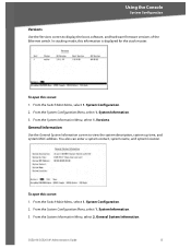
You also can enter a system contact, system name, and system location. SGE2010/SGE2010P Administration Guide 15 From the Switch Main Menu, select 1. From the System Configuration Menu, select 1. System Information. 3. Using the Console System ..., and system MAC address. General Information Use the General System Information screen to display the boot, software, and hardware firmware versions of the Ethernet switch. In stacking mode, this screen: 1. To open this screen: 1. System Information. 3. System Configuration. 2. From the System Information Menu, select...
You also can enter a system contact, system name, and system location. SGE2010/SGE2010P Administration Guide 15 From the Switch Main Menu, select 1. From the System Configuration Menu, select 1. System Information. 3. Using the Console System ..., and system MAC address. General Information Use the General System Information screen to display the boot, software, and hardware firmware versions of the Ethernet switch. In stacking mode, this screen: 1. To open this screen: 1. System Information. 3. System Configuration. 2. From the System Information Menu, select...

Administration Guide
Page 19
...can change the system contact, system name, and location: 1. From the Switch Main Menu, select 1. Select Save to the next. 2. From the System Configuration Menu, select 2. Management Settings The Management Settings screen provides access to the previous menu.) To open this screen: ...1. Telnet Configuration (see page 17) 3. SGE2010/SGE2010P Administration Guide 16 System Configuration Menu. 2. Using the Console System...
...can change the system contact, system name, and location: 1. From the Switch Main Menu, select 1. Select Save to the next. 2. From the System Configuration Menu, select 2. Management Settings The Management Settings screen provides access to the previous menu.) To open this screen: ...1. Telnet Configuration (see page 17) 3. SGE2010/SGE2010P Administration Guide 16 System Configuration Menu. 2. Using the Console System...

Administration Guide
Page 20
From the Management Settings Menu, choose 1. Select Save to the Action list. 3. SGE2010/SGE2010P Administration Guide 17 System Configuration Menu. 2. Telnet Configuration Use the Telnet Configuration screen to view or change the baud rate of the serial port: 1. ... Edit, and then make changes. 2. Press the Esc key to move the cursor to the Action list. To change the baud rate of the Ethernet switch. To open this screen: 1. When the Operation complete message appears, press the Esc key to move the cursor to save your changes. 4. Serial Port Configuration...
From the Management Settings Menu, choose 1. Select Save to the Action list. 3. SGE2010/SGE2010P Administration Guide 17 System Configuration Menu. 2. Telnet Configuration Use the Telnet Configuration screen to view or change the baud rate of the serial port: 1. ... Edit, and then make changes. 2. Press the Esc key to move the cursor to the Action list. To change the baud rate of the Ethernet switch. To open this screen: 1. When the Operation complete message appears, press the Esc key to move the cursor to save your changes. 4. Serial Port Configuration...

Administration Guide
Page 21
... to save your changes. 2. SSH Status (see page 20) 4. From the Switch Main Menu, select 1. From the Management Settings Menu, choose 3. Management Settings. 3. SSH Crypto Key Generation (see page 19) 3. From the System Configuration Menu, select 2. SGE2010/SGE2010P Administration Guide 18 From the Management Settings Menu, choose 2. Telnet Configuration. Press the Esc key to move...
... to save your changes. 2. SSH Status (see page 20) 4. From the Switch Main Menu, select 1. From the Management Settings Menu, choose 3. Management Settings. 3. SSH Crypto Key Generation (see page 19) 3. From the System Configuration Menu, select 2. SGE2010/SGE2010P Administration Guide 18 From the Management Settings Menu, choose 2. Telnet Configuration. Press the Esc key to move...


