
Administration Guide
Page 5
... indicates that the cooling fan is linked to a 100Mbps device. 2 Getting to Know the SGE2010/SGE2010P Getting to Know the SGE2010/SGE2010P This chapter describes the ports, LEDs, and other features on . These functions are 48-port, layer-2 Ethernet switches that RPS is stacked and the corresponding number indicates its default settings. These two...
... indicates that the cooling fan is linked to a 100Mbps device. 2 Getting to Know the SGE2010/SGE2010P Getting to Know the SGE2010/SGE2010P This chapter describes the ports, LEDs, and other features on . These functions are 48-port, layer-2 Ethernet switches that RPS is stacked and the corresponding number indicates its default settings. These two...

Administration Guide
Page 6
... for more information about stacking, refer to the SFE2010/SGE2010 Reference Guide. They can deliver a maximum of up to a PoE port. Ports 45, 46, 47 and 48 are shared with redundant power supply. The switch provides four mini-GBIC ports. The Fast Ethernet ports support network speeds of the device connected to it...
... for more information about stacking, refer to the SFE2010/SGE2010 Reference Guide. They can deliver a maximum of up to a PoE port. Ports 45, 46, 47 and 48 are shared with redundant power supply. The switch provides four mini-GBIC ports. The Fast Ethernet ports support network speeds of the device connected to it...
Administration Guide
Page 8
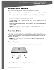
... rack mount installations. When you use the power cord that the switch will physically install the Ethernet switch. SGE2010/SGE2010P Administration Guide 5 Placement Options Before connecting cables to the switch's power port, and plug the other end into an electrical outlet. Either set the Ethernet switch on its four rubber feet for desktop placement, mount it on...
... rack mount installations. When you use the power cord that the switch will physically install the Ethernet switch. SGE2010/SGE2010P Administration Guide 5 Placement Options Before connecting cables to the switch's power port, and plug the other end into an electrical outlet. Either set the Ethernet switch on its four rubber feet for desktop placement, mount it on...

Administration Guide
Page 9
... it does not exceed the environmental restrictions mentioned in the specifications. Rack-Mount Placement To mount the Ethernet switch in the rack), follow these instructions: 1. Repeat steps 2 through 3 for reinstallation. 2. Attach the Ethernet switch to the screw holes. 3. SGE2010/SGE2010P Administration Guide 6 Place one of the supplied spacers on one side of space in any...
... it does not exceed the environmental restrictions mentioned in the specifications. Rack-Mount Placement To mount the Ethernet switch in the rack), follow these instructions: 1. Repeat steps 2 through 3 for reinstallation. 2. Attach the Ethernet switch to the screw holes. 3. SGE2010/SGE2010P Administration Guide 6 Place one of the supplied spacers on one side of space in any...

Administration Guide
Page 10
... of the side corners, remove the four front screws on of the uplink ports on the Ethernet switch. SGE2010/SGE2010P Administration Guide 7 Place one of the Ethernet switch. 5. Place a rack mount bracket next to connect additional devices. 4. NOTE: The Ethernet switch, shown below, is securely attached to the screw holes. 3. Connecting Devices to a wall, the ports can...
... of the side corners, remove the four front screws on of the uplink ports on the Ethernet switch. SGE2010/SGE2010P Administration Guide 7 Place one of the Ethernet switch. 5. Place a rack mount bracket next to connect additional devices. 4. NOTE: The Ethernet switch, shown below, is securely attached to the screw holes. 3. Connecting Devices to a wall, the ports can...

Administration Guide
Page 11
... active Gigabit connection, then its corresponding Gigabit LED will light up . 8. Each active port's corresponding Act/Link LED will also light up on the Ethernet switch. Proceed as HyperTerminal.) 6. SGE2010/SGE2010P Administration Guide 8 Power on page 50. Connect the other end into a miniGBIC port. CAUTION: Make sure you use the console interface to...
... active Gigabit connection, then its corresponding Gigabit LED will light up . 8. Each active port's corresponding Act/Link LED will also light up on the Ethernet switch. Proceed as HyperTerminal.) 6. SGE2010/SGE2010P Administration Guide 8 Power on page 50. Connect the other end into a miniGBIC port. CAUTION: Make sure you use the console interface to...
Administration Guide
Page 18
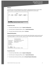
... screen: 1. General Information Use the General System Information screen to display the boot, software, and hardware firmware versions of the Ethernet switch. System Configuration. 2. General System Information. SGE2010/SGE2010P Administration Guide 15 From the Switch Main Menu, select 1. System Configuration. 2. Using the Console System Configuration Versions Use the Versions screen to view the system...
... screen: 1. General Information Use the General System Information screen to display the boot, software, and hardware firmware versions of the Ethernet switch. System Configuration. 2. General System Information. SGE2010/SGE2010P Administration Guide 15 From the Switch Main Menu, select 1. System Configuration. 2. Using the Console System Configuration Versions Use the Versions screen to view the system...

Administration Guide
Page 20
From the System Configuration Menu, select 2. To change the baud rate of the Ethernet switch. From the Switch Main Menu, select 1. Telnet Configuration Use the Telnet Configuration screen to save your changes. 4. System Configuration Menu. 2. Serial Port Configuration. Select Save to view or ... Port Configuration screen to the Action list. Press the Esc key to move the cursor to view or change the time-out settings. From the Management Settings Menu, choose 1. Select Edit, and then make changes. 2. SGE2010/SGE2010P Administration Guide 17...
From the System Configuration Menu, select 2. To change the baud rate of the Ethernet switch. From the Switch Main Menu, select 1. Telnet Configuration Use the Telnet Configuration screen to save your changes. 4. System Configuration Menu. 2. Serial Port Configuration. Select Save to view or ... Port Configuration screen to the Action list. Press the Esc key to move the cursor to view or change the time-out settings. From the Management Settings Menu, choose 1. Select Edit, and then make changes. 2. SGE2010/SGE2010P Administration Guide 17...

Administration Guide
Page 26
... City Name State or Province Name Specifies the SSL type Specifies the SSL RSA key length. (Range: 512 to 2048) IP address of the Ethernet switch Specifies the department name. (Range: 1 to 32 characters) Specifies the organization name. (Range: 1 to 32 characters) Specifies the location or ...the Tab key to move the cursor to field. 2. Select Edit, and then make your changes. Select Execute to 32 characters) SGE2010/SGE2010P Administration Guide 23 Using the Console System Configuration SSL Generate Certificate Use the SSL Certificate Generation screen to the Action list. 3. When...
... City Name State or Province Name Specifies the SSL type Specifies the SSL RSA key length. (Range: 512 to 2048) IP address of the Ethernet switch Specifies the department name. (Range: 1 to 32 characters) Specifies the organization name. (Range: 1 to 32 characters) Specifies the location or ...the Tab key to move the cursor to field. 2. Select Edit, and then make your changes. Select Execute to 32 characters) SGE2010/SGE2010P Administration Guide 23 Using the Console System Configuration SSL Generate Certificate Use the SSL Certificate Generation screen to the Action list. 3. When...

Administration Guide
Page 45
...Active Image. The cursor moves to specify which image is replaced. The selected image will be active after Reset field. 2. SGE2010/SGE2010P Administration Guide 42 From the Switch Main Menu, select 1. File Management. 3. Select Edit. When the Operation complete message appears, press the Esc key to move the cursor to the Action list.... 4. To open this screen: 1. When the correct image setting appears in the field, press the Esc key to move the cursor to the switch via TFTP, the inactive image is the active image on the Ethernet switch: Image 1 and Image 2.
...Active Image. The cursor moves to specify which image is replaced. The selected image will be active after Reset field. 2. SGE2010/SGE2010P Administration Guide 42 From the Switch Main Menu, select 1. File Management. 3. Select Edit. When the Operation complete message appears, press the Esc key to move the cursor to the Action list.... 4. To open this screen: 1. When the correct image setting appears in the field, press the Esc key to move the cursor to the switch via TFTP, the inactive image is the active image on the Ethernet switch: Image 1 and Image 2.

Administration Guide
Page 46
..., select 1. From the System Configuration Menu, select 9. SGE2010/SGE2010P Administration Guide 43 To restore factory default settings 1. To reset stacking configuration, use the hardware reset button on the front of the Ethernet switch. Reboot System You can restore the switch to Factory Settings You can restart the Ethernet switch. System Configuration. 2. When the confirmation message appears...
..., select 1. From the System Configuration Menu, select 9. SGE2010/SGE2010P Administration Guide 43 To restore factory default settings 1. To reset stacking configuration, use the hardware reset button on the front of the Ethernet switch. Reboot System You can restore the switch to Factory Settings You can restart the Ethernet switch. System Configuration. 2. When the confirmation message appears...

Administration Guide
Page 47
... 2. To open this screen: 1. SGE2010/SGE2010P Administration Guide 44 System Configuration. 2. Port Status (see page 45) 0.Back (Select to return to each port on the switch. 1. Stack Configuration. Using the Console Port Status Stack Configuration You can view the port status and the PoE status for the Ethernet switch. From the Switch Main Menu, select 1.
... 2. To open this screen: 1. SGE2010/SGE2010P Administration Guide 44 System Configuration. 2. Port Status (see page 45) 0.Back (Select to return to each port on the switch. 1. Stack Configuration. Using the Console Port Status Stack Configuration You can view the port status and the PoE status for the Ethernet switch. From the Switch Main Menu, select 1.

Administration Guide
Page 49
...(see page 47) 0.Back (Select to return to screens where you can use the Port Settings screen to scroll through all the ports on the Ethernet switch. Port Configuration. To open this screen: 1. Poe Status. You can view or modify port settings and PoE settings. 1. Using the Console Port ...Configuration Port Configuration The Port Configuration Menu provides access to the previous screen.) From the Switch Main Menu, press 3. SGE2010/SGE2010P Administration Guide 46 From the Switch Main Menu, press 3. PoE Settings (see page 46) 2.
...(see page 47) 0.Back (Select to return to screens where you can use the Port Settings screen to scroll through all the ports on the Ethernet switch. Port Configuration. To open this screen: 1. Poe Status. You can view or modify port settings and PoE settings. 1. Using the Console Port ...Configuration Port Configuration The Port Configuration Menu provides access to the previous screen.) From the Switch Main Menu, press 3. SGE2010/SGE2010P Administration Guide 46 From the Switch Main Menu, press 3. PoE Settings (see page 46) 2.

Administration Guide
Page 50
... move the cursor to scroll through the list of ports. Poe Settings. Proceed as needed: a. From the Switch Main Menu, press 3. SGE2010/SGE2010P Administration Guide 47 Select Save to the Action list. b. Press the Esc key to move the cursor ...to save your settings 5. You can use the up or down arrow keys to the Action list. 4. Port Configuration. 2. Select Edit. 2. Press the down through all the ports on the Ethernet switch...
... move the cursor to scroll through the list of ports. Poe Settings. Proceed as needed: a. From the Switch Main Menu, press 3. SGE2010/SGE2010P Administration Guide 47 Select Save to the Action list. b. Press the Esc key to move the cursor ...to save your settings 5. You can use the up or down arrow keys to the Action list. 4. Port Configuration. 2. Select Edit. 2. Press the down through all the ports on the Ethernet switch...
Administration Guide
Page 51
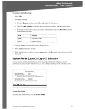
Press the right arrow key to specify whether the Ethernet switch is operating in Layer 2 or Layer 3 mode. Field Priority Enable Settings Low, High, or Critical Enable or Disable 3. When the Operation complete message appears, press ..., move the cursor to the field, and then press the Space Bar until the desired setting appears. SGE2010/SGE2010P Administration Guide 48 Press the Esc key to move the cursor from this screen: From the Switch Main Menu, press 4. You can use the System Mode Selection screen to move the cursor to...
Press the right arrow key to specify whether the Ethernet switch is operating in Layer 2 or Layer 3 mode. Field Priority Enable Settings Low, High, or Critical Enable or Disable 3. When the Operation complete message appears, press ..., move the cursor to the field, and then press the Space Bar until the desired setting appears. SGE2010/SGE2010P Administration Guide 48 Press the Esc key to move the cursor from this screen: From the Switch Main Menu, press 4. You can use the System Mode Selection screen to move the cursor to...

Administration Guide
Page 52
... Menu, press 5. Using the Console Help To edit the system mode or stacking mode: 1. c. Field System Mode after Reset Stacking Mode after reboot. Reboot the Ethernet switch. b. Select Save to scroll down through the list of ports. Your new settings will take effect after Reset Settings Layer 2 or Layer 3 Stack or Standalone... menus and options. Help You can use the Help screen to the field, and then press the Space Bar until the desired setting appears. Help. SGE2010/SGE2010P Administration Guide 49
... Menu, press 5. Using the Console Help To edit the system mode or stacking mode: 1. c. Field System Mode after Reset Stacking Mode after reboot. Reboot the Ethernet switch. b. Select Save to scroll down through the list of ports. Your new settings will take effect after Reset Settings Layer 2 or Layer 3 Stack or Standalone... menus and options. Help You can use the Help screen to the field, and then press the Space Bar until the desired setting appears. Help. SGE2010/SGE2010P Administration Guide 49

Administration Guide
Page 53
SGE2010/SGE2010P Administration Guide 50 NOTE: When you issue this command, you logout from the Ethernet switch. Using the Console Logout Logout The Logout command lets you are immediately logged off the Ethernet switch.
SGE2010/SGE2010P Administration Guide 50 NOTE: When you issue this command, you logout from the Ethernet switch. Using the Console Logout Logout The Logout command lets you are immediately logged off the Ethernet switch.

Administration Guide
Page 62
... Forwarding Capacity LEDs Stack Operation Buttons Layer 2 options Layer 3 options • SGE2010 48-port 10/100/1000 Ethernet Switch • SGE2010P 48-port 10/100/1000 Ethernet Switch with PoE • IEEE 802.3af PoE on delivered over any of the 48 10/100 ports • Power budget allows for max power of ... IPv4 and IPv6 Forwarding in stack Reset Button 8K 256 active VLANs (4096 range) Port-based and 802.1Q Tag-based VLANs Protocol-based VLAN Management VLAN Multicast TV VLAN Private VLAN Edge (PVE) GVRP Head of layer 3 traffic...
... Forwarding Capacity LEDs Stack Operation Buttons Layer 2 options Layer 3 options • SGE2010 48-port 10/100/1000 Ethernet Switch • SGE2010P 48-port 10/100/1000 Ethernet Switch with PoE • IEEE 802.3af PoE on delivered over any of the 48 10/100 ports • Power budget allows for max power of ... IPv4 and IPv6 Forwarding in stack Reset Button 8K 256 active VLANs (4096 range) Port-based and 802.1Q Tag-based VLANs Protocol-based VLAN Management VLAN Multicast TV VLAN Private VLAN Edge (PVE) GVRP Head of layer 3 traffic...


