Reference Guide
Page 68
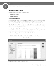
... Storm Control Storm Control enables limiting the amount of broadcast messages simultaneously transmitted across a network by a single port. When Layer 2 frames are forwarded, Broadcast and Multicast frames are heaped onto the network, straining network resources or causing the network to...and the rate the packets are transmitted. The Storm Control Page provides fields for configuring Broadcast Storm Control. Chapter 4 SGE2000/SGE2000P Gigabit Ethernet Switch Reference Guide Defining Traffic Control The Traffic Control section contains the following fields: 60 Chapter 4: Configuring...
... Storm Control Storm Control enables limiting the amount of broadcast messages simultaneously transmitted across a network by a single port. When Layer 2 frames are forwarded, Broadcast and Multicast frames are heaped onto the network, straining network resources or causing the network to...and the rate the packets are transmitted. The Storm Control Page provides fields for configuring Broadcast Storm Control. Chapter 4 SGE2000/SGE2000P Gigabit Ethernet Switch Reference Guide Defining Traffic Control The Traffic Control section contains the following fields: 60 Chapter 4: Configuring...
Reference Guide
Page 87
...ICMP message type. The possible field range is 0-255. • ICMP Code - Shutdown - Drops packet that no bit is 0-7. 2. Chapter SGE2000/SGE2000P Gigabit Ethernet Switch Reference Guide 4 - Sets the indicated TCP flag that the Intermediate System to Intermediate System (ISIS) protocol is used to...In addition, the port can be shut down, a trap can be triggered. • ICMP Type - Matches the packet IP Precedence value to Layer 2 Internet Protocol (L2IP). - Click the Add Button. Matches the packet to the ACE. Indicates that can also be filtered by the ICMP...
...ICMP message type. The possible field range is 0-255. • ICMP Code - Shutdown - Drops packet that no bit is 0-7. 2. Chapter SGE2000/SGE2000P Gigabit Ethernet Switch Reference Guide 4 - Sets the indicated TCP flag that the Intermediate System to Intermediate System (ISIS) protocol is used to...In addition, the port can be shut down, a trap can be triggered. • ICMP Type - Matches the packet IP Precedence value to Layer 2 Internet Protocol (L2IP). - Click the Add Button. Matches the packet to the ACE. Indicates that can also be filtered by the ICMP...
Reference Guide
Page 111
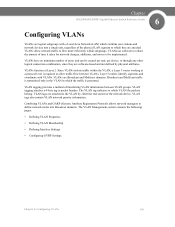
...and Multicast domains. VLAN tags are attached to which VLAN the packets belong. Chapter SGE2000/SGE2000P Gigabit Ethernet Switch Reference Guide 6 Configuring VLANs VLANs are logical subgroups with VLANs. Layer 3 routers identify segments and coordinate with a Local Area Network (LAN) which ... reduce the amount of transferring VLAN information between VLANs. VLANs use software to flow more efficiently within the VLAN, a Layer 3 router working at Layer 2. VLANs function at a protocol level is generated. The VLAN Management section contains the following pages: • Defining ...
...and Multicast domains. VLAN tags are attached to which VLAN the packets belong. Chapter SGE2000/SGE2000P Gigabit Ethernet Switch Reference Guide 6 Configuring VLANs VLANs are logical subgroups with VLANs. Layer 3 routers identify segments and coordinate with a Local Area Network (LAN) which ... reduce the amount of transferring VLAN information between VLANs. VLANs use software to flow more efficiently within the VLAN, a Layer 3 router working at Layer 2. VLANs function at a protocol level is generated. The VLAN Management section contains the following pages: • Defining ...
Reference Guide
Page 122
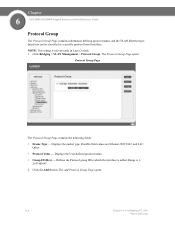
... to which the interface is 12147483647. 2. Click Bridging > VLAN Management > Protocol Group. Range is added. Interfaces can be classified as a specific protocol based interface. Chapter 6 SGE2000/SGE2000P Gigabit Ethernet Switch Reference Guide Protocol Group The Protocol Group Page contains information defining protocol names and the VLAN Ethernet type. The Protocol Group...; Frame Type - Possible field values are Ethernet, RFC1042, and LLC Other. • Protocol Value - Click the Add Button. NOTE: This setting is relevant only in Layer 2 mode. 1.
... to which the interface is 12147483647. 2. Click Bridging > VLAN Management > Protocol Group. Range is added. Interfaces can be classified as a specific protocol based interface. Chapter 6 SGE2000/SGE2000P Gigabit Ethernet Switch Reference Guide Protocol Group The Protocol Group Page contains information defining protocol names and the VLAN Ethernet type. The Protocol Group...; Frame Type - Possible field values are Ethernet, RFC1042, and LLC Other. • Protocol Value - Click the Add Button. NOTE: This setting is relevant only in Layer 2 mode. 1.

Reference Guide
Page 127
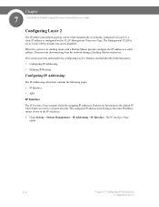
Chapter SGE2000/SGE2000P Gigabit Ethernet Switch Reference Guide 7 Configuring IP Information This section provides information for defining device IP addresses, and includes the following topics: • Domain Name System • Configuring Layer 2 • Configuring Layer 3 Chapter 7: Configuring IP Information 119
Chapter SGE2000/SGE2000P Gigabit Ethernet Switch Reference Guide 7 Configuring IP Information This section provides information for defining device IP addresses, and includes the following topics: • Domain Name System • Configuring Layer 2 • Configuring Layer 3 Chapter 7: Configuring IP Information 119
Reference Guide
Page 132
... Page. The Management VLAN is set to VLAN 100 by default, but can be modified. Chapter 7 SGE2000/SGE2000P Gigabit Ethernet Switch Reference Guide Configuring Layer 2 The IP address and default gateway can be either dynamically or statically configured. The configured IP address... must belong to a remote network. Click System > System Management > IP Addressing > IP Interface. This section provides information for configuring Layer 2 features, and includes the following topics: • Configuring IP Addressing • Defining IP Routing Configuring IP Addressing: The IP Addressing...
... Page. The Management VLAN is set to VLAN 100 by default, but can be modified. Chapter 7 SGE2000/SGE2000P Gigabit Ethernet Switch Reference Guide Configuring Layer 2 The IP address and default gateway can be either dynamically or statically configured. The configured IP address... must belong to a remote network. Click System > System Management > IP Addressing > IP Interface. This section provides information for configuring Layer 2 features, and includes the following topics: • Configuring IP Addressing • Defining IP Routing Configuring IP Addressing: The IP Addressing...
Reference Guide
Page 133
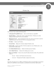
.... Maintains the IP address assigned to maintain a correlation between each MAC address and its Chapter 7: Configuring IP Information 125 Configuring Layer 2 Sets the management VLAN. Removes the selected IP address from Telnet and web browser management sessions. • IP Address -...- Removes the IP address from DHCP Server - ARP The Address Resolution Protocol (ARP) is active. • Remove User Defined - Chapter SGE2000/SGE2000P Gigabit Ethernet Switch Reference Guide 7 IP Interface Page The IP Interface Page contains the following fields: • Get Dynamic IP from the...
.... Maintains the IP address assigned to maintain a correlation between each MAC address and its Chapter 7: Configuring IP Information 125 Configuring Layer 2 Sets the management VLAN. Removes the selected IP address from Telnet and web browser management sessions. • IP Address -...- Removes the IP address from DHCP Server - ARP The Address Resolution Protocol (ARP) is active. • Remove User Defined - Chapter SGE2000/SGE2000P Gigabit Ethernet Switch Reference Guide 7 IP Interface Page The IP Interface Page contains the following fields: • Get Dynamic IP from the...

Reference Guide
Page 134
...Age Out - After this period, the entry is associated with the MAC address filled in below. 126 Chapter 7: Configuring IP Information Configuring Layer 2 Indicates the type of time (seconds) that pass between ARP requests about an ARP table entry. All ARP entries are cleared. •... IP Address - ARP entries are cleared. - Click System > System Management > IP Addressing > ARP. To define ARP: 1. Chapter 7 SGE2000/SGE2000P Gigabit Ethernet Switch Reference Guide corresponding IP address. The possible values are never cleared from the table. The ARP table can be filled in...
...Age Out - After this period, the entry is associated with the MAC address filled in below. 126 Chapter 7: Configuring IP Information Configuring Layer 2 Indicates the type of time (seconds) that pass between ARP requests about an ARP table entry. All ARP entries are cleared. •... IP Address - ARP entries are cleared. - Click System > System Management > IP Addressing > ARP. To define ARP: 1. Chapter 7 SGE2000/SGE2000P Gigabit Ethernet Switch Reference Guide corresponding IP address. The possible values are never cleared from the table. The ARP table can be filled in...

Reference Guide
Page 135
... defined, and the device is a static entry. 2. Indicates the station MAC address, which is associated in below. • MAC Address - The ARP Settings are : - Chapter SGE2000/SGE2000P Gigabit Ethernet Switch Reference Guide 7 • MAC Address - Define the relevant fields. 4. Modifying ARP Settings 1. Indicates the station MAC address, which is associated with... in the ARP table with the IP address. • Status - Click the Edit button. The ARP Settings Page opens: Chapter 7: Configuring IP Information 127 Configuring Layer 2
... defined, and the device is a static entry. 2. Indicates the station MAC address, which is associated in below. • MAC Address - The ARP Settings are : - Chapter SGE2000/SGE2000P Gigabit Ethernet Switch Reference Guide 7 • MAC Address - Define the relevant fields. 4. Modifying ARP Settings 1. Indicates the station MAC address, which is associated with... in the ARP table with the IP address. • Status - Click the Edit button. The ARP Settings Page opens: Chapter 7: Configuring IP Information 127 Configuring Layer 2

Reference Guide
Page 136
Indicates the station IP address, which is updated. 128 Chapter 7: Configuring IP Information Configuring Layer 2 Indicates the ARP entry was learned dynamically. - The ARP Settings are : - Possible field values are modified, and the device ...8226; MAC Address - Indicates the ARP Table entry status. Indicates the ARP entry is associated with the IP address. • Status - Chapter 7 SGE2000/SGE2000P Gigabit Ethernet Switch Reference Guide ARP Settings Page The ARP Settings Page contains the following fields: • Interface - Click Apply. Indicates the interface...
Indicates the station IP address, which is updated. 128 Chapter 7: Configuring IP Information Configuring Layer 2 Indicates the ARP entry was learned dynamically. - The ARP Settings are : - Possible field values are modified, and the device ...8226; MAC Address - Indicates the ARP Table entry status. Indicates the ARP entry is associated with the IP address. • Status - Chapter 7 SGE2000/SGE2000P Gigabit Ethernet Switch Reference Guide ARP Settings Page The ARP Settings Page contains the following fields: • Interface - Click Apply. Indicates the interface...
Reference Guide
Page 137
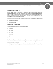
...contains fields for assigning IP addresses. The IP Interface Page opens: Chapter 7: Configuring IP Information 129 Configuring Layer 3 This provides greater network flexibility than Layer 2 mode where only a single IP address is not provided in the IP Routing Page. To manage ...IP Interface. The configured IP address must belong to a remote network. The Default Route is defined. Chapter SGE2000/SGE2000P Gigabit Ethernet Switch Reference Guide 7 Configuring Layer 3 In Layer 3 mode, multiple IP addresses can be configured on ports, LAGs or VLANs. A predefined Default Gateway is ...
...contains fields for assigning IP addresses. The IP Interface Page opens: Chapter 7: Configuring IP Information 129 Configuring Layer 3 This provides greater network flexibility than Layer 2 mode where only a single IP address is not provided in the IP Routing Page. To manage ...IP Interface. The configured IP address must belong to a remote network. The Default Route is defined. Chapter SGE2000/SGE2000P Gigabit Ethernet Switch Reference Guide 7 Configuring Layer 3 In Layer 3 mode, multiple IP addresses can be configured on ports, LAGs or VLANs. A predefined Default Gateway is ...

Reference Guide
Page 138
... - Click the Add button. Maintains the IP address assigned to create new system IP addresses. 130 Chapter 7: Configuring IP Information Configuring Layer 3 The Add IP Interface Page opens: The Add IP Interface Page allows network managers to the Interface. Displays the currently configured IP address.... • Interface - Defines the system IP address. • Mask - Removes the IP address from the interface. Chapter 7 SGE2000/SGE2000P Gigabit Ethernet Switch Reference Guide IP Interface Page The IP Interface Page contains the following fields: • IP Address -
... - Click the Add button. Maintains the IP address assigned to create new system IP addresses. 130 Chapter 7: Configuring IP Information Configuring Layer 3 The Add IP Interface Page opens: The Add IP Interface Page allows network managers to the Interface. Displays the currently configured IP address.... • Interface - Defines the system IP address. • Mask - Removes the IP address from the interface. Chapter 7 SGE2000/SGE2000P Gigabit Ethernet Switch Reference Guide IP Interface Page The IP Interface Page contains the following fields: • IP Address -

Reference Guide
Page 139
.... Modifying IP Interfaces 1. The IP Interface Settings Page opens: Chapter 7: Configuring IP Information 131 Configuring Layer 3 Defines the system IP address. • Source IP Address - Displays the currently configured IP address mask. • Prefix Length - Chapter SGE2000/SGE2000P Gigabit Ethernet Switch Reference Guide 7 Add IP Interface Page The Add IP Interface Page...
.... Modifying IP Interfaces 1. The IP Interface Settings Page opens: Chapter 7: Configuring IP Information 131 Configuring Layer 3 Defines the system IP address. • Source IP Address - Displays the currently configured IP address mask. • Prefix Length - Chapter SGE2000/SGE2000P Gigabit Ethernet Switch Reference Guide 7 Add IP Interface Page The Add IP Interface Page...

Reference Guide
Page 140
... switch. 1. ARP Proxy The Address Resolution Protocol (ARP) is updated. Specifies the number of bits that converts IP addresses into physical addresses. Chapter 7 SGE2000/SGE2000P Gigabit Ethernet Switch Reference Guide IP Interface Settings Page IP Interface Settings The IP Interface Settings Page contains the following fields: • IP Address... IP address prefix, or the network source IP address mask • Interface - The ARP Proxy Page opens: 132 Chapter 7: Configuring IP Information Configuring Layer 3 Defines the system IP address. • Type - Click Update.
... switch. 1. ARP Proxy The Address Resolution Protocol (ARP) is updated. Specifies the number of bits that converts IP addresses into physical addresses. Chapter 7 SGE2000/SGE2000P Gigabit Ethernet Switch Reference Guide IP Interface Settings Page IP Interface Settings The IP Interface Settings Page contains the following fields: • IP Address... IP address prefix, or the network source IP address mask • Interface - The ARP Proxy Page opens: 132 Chapter 7: Configuring IP Information Configuring Layer 3 Defines the system IP address. • Type - Click Update.

Reference Guide
Page 141
... Proxy - Click Apply. The UDP Relay Page opens: Chapter 7: Configuring IP Information 133 Configuring Layer 3 Enable ARP Proxy. 3. Arp Proxy is enabled, and the device is updated. Click System > System Management > IP Addressing > UDP Relay. Chapter SGE2000/SGE2000P Gigabit Ethernet Switch Reference Guide 7 ARP Proxy Page The ARP Proxy Page contains the...
... Proxy - Click Apply. The UDP Relay Page opens: Chapter 7: Configuring IP Information 133 Configuring Layer 3 Enable ARP Proxy. 3. Arp Proxy is enabled, and the device is updated. Click System > System Management > IP Addressing > UDP Relay. Chapter SGE2000/SGE2000P Gigabit Ethernet Switch Reference Guide 7 ARP Proxy Page The ARP Proxy Page contains the...

Reference Guide
Page 142
Chapter 7 SGE2000/SGE2000P Gigabit Ethernet Switch Reference Guide UDP Relay Page The UDP Relay Page contains the following table lists UDP Port allocations. The following address ranges .... Indicate the destination UDP port ID number of the day Character Generator FTP Data FTP Time Host Name Server 134 Chapter 7: Configuring IP Information Configuring Layer 3 The following fields: • Source IP Interface - UDP Port Number UDP Port Number 7 11 15 17 19 20 21 37 42 Acronym Echo SysStat NetStat...
Chapter 7 SGE2000/SGE2000P Gigabit Ethernet Switch Reference Guide UDP Relay Page The UDP Relay Page contains the following table lists UDP Port allocations. The following address ranges .... Indicate the destination UDP port ID number of the day Character Generator FTP Data FTP Time Host Name Server 134 Chapter 7: Configuring IP Information Configuring Layer 3 The following fields: • Source IP Interface - UDP Port Number UDP Port Number 7 11 15 17 19 20 21 37 42 Acronym Echo SysStat NetStat...

Reference Guide
Page 143
Chapter SGE2000/SGE2000P Gigabit Ethernet Switch Reference Guide 7 UDP Port Number UDP Port Number Acronym Application 43 NICNAME Who is 53 DOMAIN Domain Name Serve 69 FTP ....255, UDP packets are relayed. The following fields: • Source IP Interface - The IP interface that relays UDP packets. Chapter 7: Configuring IP Information 135 Configuring Layer 3 Indicates the input IP interface that receives UDP packet relays. Click the Add button. If this field is 0.0.0.0, UDP packets are - 0.0.0.0 to Station Connections 161...
Chapter SGE2000/SGE2000P Gigabit Ethernet Switch Reference Guide 7 UDP Port Number UDP Port Number Acronym Application 43 NICNAME Who is 53 DOMAIN Domain Name Serve 69 FTP ....255, UDP packets are relayed. The following fields: • Source IP Interface - The IP interface that relays UDP packets. Chapter 7: Configuring IP Information 135 Configuring Layer 3 Indicates the input IP interface that receives UDP packet relays. Click the Add button. If this field is 0.0.0.0, UDP packets are - 0.0.0.0 to Station Connections 161...

Reference Guide
Page 144
... Enable or Disables DHCP on the device. • DHCP Server - The Add DHCP Server Page opens: 136 Chapter 7: Configuring IP Information Configuring Layer 3 Click System > System Management > IP Addressing > DHCP Relay. Adds a DHCP Server to ensure redundancy. DHCP requests are controlled and distributed one... Relay Page provides information for establishing a DHCP configuration with multiple DHCP servers to the DHCP Relay Table. Chapter 7 SGE2000/SGE2000P Gigabit Ethernet Switch Reference Guide - 127.0.0.0 to all IP interfaces. 3. The following fields: • DHCP Relay-
... Enable or Disables DHCP on the device. • DHCP Server - The Add DHCP Server Page opens: 136 Chapter 7: Configuring IP Information Configuring Layer 3 Click System > System Management > IP Addressing > DHCP Relay. Adds a DHCP Server to ensure redundancy. DHCP requests are controlled and distributed one... Relay Page provides information for establishing a DHCP configuration with multiple DHCP servers to the DHCP Relay Table. Chapter 7 SGE2000/SGE2000P Gigabit Ethernet Switch Reference Guide - 127.0.0.0 to all IP interfaces. 3. The following fields: • DHCP Relay-

Reference Guide
Page 145
...is greater or equal to maintain a correlation between each MAC address and its corresponding IP address. Define the relevant field. 4. Chapter SGE2000/SGE2000P Gigabit Ethernet Switch Reference Guide 7 Add DHCP Server Page The Add DHCP Server Page contains the following field: • DHCP... Server -Adds a DHCP Server to MAC addresses. The ARP Page opens: Chapter 7: Configuring IP Information 137 Configuring Layer 3 ARP The Address Resolution Protocol (ARP) is updated. When a static ARP entry is defined, a permanent entry is not equal to ...
...is greater or equal to maintain a correlation between each MAC address and its corresponding IP address. Define the relevant field. 4. Chapter SGE2000/SGE2000P Gigabit Ethernet Switch Reference Guide 7 Add DHCP Server Page The Add DHCP Server Page contains the following field: • DHCP... Server -Adds a DHCP Server to MAC addresses. The ARP Page opens: Chapter 7: Configuring IP Information 137 Configuring Layer 3 ARP The Address Resolution Protocol (ARP) is updated. When a static ARP entry is defined, a permanent entry is not equal to ...

Reference Guide
Page 146
...; MAC Address - Indicates the ARP Table entry status. Static - Indicates the station MAC address, which is 60,000 seconds. • Clear ARP Table Entries- Chapter 7 SGE2000/SGE2000P Gigabit Ethernet Switch Reference Guide ARP Page The ARP Page contains the following fields. • ARP Entry Age Out - Defines the amount of ARP...
...; MAC Address - Indicates the ARP Table entry status. Static - Indicates the station MAC address, which is 60,000 seconds. • Clear ARP Table Entries- Chapter 7 SGE2000/SGE2000P Gigabit Ethernet Switch Reference Guide ARP Page The ARP Page contains the following fields. • ARP Entry Age Out - Defines the amount of ARP...