Reference Guide
Page 22
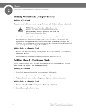
... to the stack. 14 Chapter 2: Managing Device Information Building Automatically-Configured Stacks Reset all relevant units to by restoring them . 1. Chapter 2 SGE2000/SGE2000P Gigabit Ethernet Switch Reference Guide Building Automatically-Configured Stacks Building a New Stack The easiest way to build a stack is to use a group... the stack. The unit selected as the Stack Master. If a serial console connection is desired, the serial cable should be used in factory default mode: NOTE: If the units to be connected to the factory default by holding the reset button for at least 10 ...
... to the stack. 14 Chapter 2: Managing Device Information Building Automatically-Configured Stacks Reset all relevant units to by restoring them . 1. Chapter 2 SGE2000/SGE2000P Gigabit Ethernet Switch Reference Guide Building Automatically-Configured Stacks Building a New Stack The easiest way to build a stack is to use a group... the stack. The unit selected as the Stack Master. If a serial console connection is desired, the serial cable should be used in factory default mode: NOTE: If the units to be connected to the factory default by holding the reset button for at least 10 ...
Reference Guide
Page 23
...is the Stack Master, and its desired Unit ID (using the Stack Management Interface through the console port, by Telnet, or by using the graphical user interface (GUI). 4. Assign each ...Master The unit assigned the Unit ID number 1 serves as the stack Backup Master. Chapter SGE2000/SGE2000P Gigabit Ethernet Switch Reference Guide 2 3. Power the units on. The unit that serves...interval, they are stack members. The unit assigned the Unit ID 2 is present, we recommend connecting the Stack Master and Backup Master units to make this assignment permanent. The Stack Master provides ...
...is the Stack Master, and its desired Unit ID (using the Stack Management Interface through the console port, by Telnet, or by using the graphical user interface (GUI). 4. Assign each ...Master The unit assigned the Unit ID number 1 serves as the stack Backup Master. Chapter SGE2000/SGE2000P Gigabit Ethernet Switch Reference Guide 2 3. Power the units on. The unit that serves...interval, they are stack members. The unit assigned the Unit ID 2 is present, we recommend connecting the Stack Master and Backup Master units to make this assignment permanent. The Stack Master provides ...
Reference Guide
Page 50
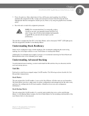
...password for authentication. - RADIUS - SSH provides clients secure and encrypted remote connections to authenticate Secure Shell (SSH) users. TACACS+ - Indicates that Authentication profiles are used to authenticate console users. • Telnet - The possible field values are used to a... device. • Secure HTTP - Local - Authenticates the user at the RADIUS server. - Mapping Profiles 1. Chapter 4 SGE2000/SGE2000P Gigabit Ethernet Switch Reference ...
...password for authentication. - RADIUS - SSH provides clients secure and encrypted remote connections to authenticate Secure Shell (SSH) users. TACACS+ - Indicates that Authentication profiles are used to authenticate console users. • Telnet - The possible field values are used to a... device. • Secure HTTP - Local - Authenticates the user at the RADIUS server. - Mapping Profiles 1. Chapter 4 SGE2000/SGE2000P Gigabit Ethernet Switch Reference ...
Configuration Guide
Page 5
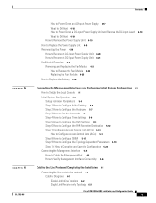
... Fan Module 4-24 Replacing the Fan Module 4-25 How to Replace the Battery 4-26 Connecting the Management Interfaces and Performing Initial System Configuration 5-1 How to Set Up the Local Console 5-1 Initial System Configuration 5-3 Setup Command Parameters 5-4 Step 1: How to Configure Initial Settings...How to Complete and Save the Configuration 5-23 Connecting the Management Interface 5-25 How to Cable the Management Port 5-25 How to Verify Management Interface Connectivity 5-26 Cabling the Line Ports and Completing the Installation 6-1 Connecting the line ports to the network 6-1 Cabling ...
... Fan Module 4-24 Replacing the Fan Module 4-25 How to Replace the Battery 4-26 Connecting the Management Interfaces and Performing Initial System Configuration 5-1 How to Set Up the Local Console 5-1 Initial System Configuration 5-3 Setup Command Parameters 5-4 Step 1: How to Configure Initial Settings...How to Complete and Save the Configuration 5-23 Connecting the Management Interface 5-25 How to Cable the Management Port 5-25 How to Verify Management Interface Connectivity 5-26 Cabling the Line Ports and Completing the Installation 6-1 Connecting the line ports to the network 6-1 Cabling ...

Configuration Guide
Page 10
Cisco SCE 2000 4xGBE Installation and Configuration Guide x OL-7824-06 Connecting the Management Interfaces and Performing Initial System Configuration This chapter explains how to connect the SCE 2000 platform to start up the SCE 2000 platform, reboot, and shutdown. Cabling the Line..., and for configuring Gigabit Ethernet (GBE) interface parameters. Basic SCE 2000 Platform Operations This chapter describes how to a local console and perform the initial system configuration via the setup wizard that runs automatically. It also describes how to install or replace the...
Cisco SCE 2000 4xGBE Installation and Configuration Guide x OL-7824-06 Connecting the Management Interfaces and Performing Initial System Configuration This chapter explains how to connect the SCE 2000 platform to start up the SCE 2000 platform, reboot, and shutdown. Cabling the Line..., and for configuring Gigabit Ethernet (GBE) interface parameters. Basic SCE 2000 Platform Operations This chapter describes how to a local console and perform the initial system configuration via the setup wizard that runs automatically. It also describes how to install or replace the...
Configuration Guide
Page 17
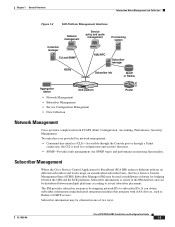
... It can be used for network management: • Command-line interface (CLI)-Accessible through the Console port or through a Telnet connection, the CLI is stored in one of two ways: OL-7824-06 Cisco SCE 2000 4xGBE Installation and Configuration Guide 1-5 The SM provides subscriber awareness by mapping network IDs ... 92763 Aggregation device MNG 1 MNG 2 ALCITNIKV/E1100/10000/ ALCITNIKV/E1100/10000/ CONSOLE AUX PWR A PWR B STATUS BYPASS LINK RX TX LINK RX TX RX MM TX RX MM TX GBE-1 SUB LINE NET Cisco S4CxEG2B0E00 Series LINK RX TX LINK RX TX RX MM TX RX MM TX ...
... It can be used for network management: • Command-line interface (CLI)-Accessible through the Console port or through a Telnet connection, the CLI is stored in one of two ways: OL-7824-06 Cisco SCE 2000 4xGBE Installation and Configuration Guide 1-5 The SM provides subscriber awareness by mapping network IDs ... 92763 Aggregation device MNG 1 MNG 2 ALCITNIKV/E1100/10000/ ALCITNIKV/E1100/10000/ CONSOLE AUX PWR A PWR B STATUS BYPASS LINK RX TX LINK RX TX RX MM TX RX MM TX GBE-1 SUB LINE NET Cisco S4CxEG2B0E00 Series LINK RX TX LINK RX TX RX MM TX RX MM TX ...
Configuration Guide
Page 20
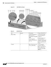
...GBE-2 SUB LINE/CASCADE NET GBE-1 SUB LINE NET Cisco S4CxEG2B0E00 LINK RX TX LINK RX TX RX MM TX RX MM TX GBE-2 SUB LINE/CASCADE NET Table 2-2 SCE 2000 Ports Port Mng1/ Mng2 Quantity 2 Console 1 Description Connect This Port To... 10/100/1000 Ethernet A LAN ... local terminal (console) using an FE RJ-45 ports for cable with an RJ-45 connector, as provided in the SCE 2000 kit. If both ports to provide a interface Management redundant management 0/1, 0/2. Cisco SCE 2000 4xGBE Installation and Configuration Guide 2-2 OL-7824-06 interface, connect both interfaces are...
...GBE-2 SUB LINE/CASCADE NET GBE-1 SUB LINE NET Cisco S4CxEG2B0E00 LINK RX TX LINK RX TX RX MM TX RX MM TX GBE-2 SUB LINE/CASCADE NET Table 2-2 SCE 2000 Ports Port Mng1/ Mng2 Quantity 2 Console 1 Description Connect This Port To... 10/100/1000 Ethernet A LAN ... local terminal (console) using an FE RJ-45 ports for cable with an RJ-45 connector, as provided in the SCE 2000 kit. If both ports to provide a interface Management redundant management 0/1, 0/2. Cisco SCE 2000 4xGBE Installation and Configuration Guide 2-2 OL-7824-06 interface, connect both interfaces are...

Configuration Guide
Page 25
...verification is completed, place it in your site log along with your installation and to console port FE management ports are operational GBE line and cascade ports operational OL-7824-06 Cisco SCE 2000 4xGBE Installation and Configuration Guide 2-7 When the checklist is completed. Chapter ..., device names, and so on, needed for initial configuration available Required tools available Network connection equipment available SCE 2000 mounted in rack (optional) AC/DC power cables connected to AC/DC sources and SCE 2000 platform Console port set for your new SCE 2000 platform.
...verification is completed, place it in your site log along with your installation and to console port FE management ports are operational GBE line and cascade ports operational OL-7824-06 Cisco SCE 2000 4xGBE Installation and Configuration Guide 2-7 When the checklist is completed. Chapter ..., device names, and so on, needed for initial configuration available Required tools available Network connection equipment available SCE 2000 mounted in rack (optional) AC/DC power cables connected to AC/DC sources and SCE 2000 platform Console port set for your new SCE 2000 platform.
Configuration Guide
Page 40
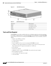
... leads Ring terminals must be UL approved and suitable for 12 AWG wire. • Level (optional) • Tape measure (optional) • Appropriate cables to connect the SCE 2000 to Install the SCE 2000 Platform Chapter 4 Installation and Maintenance Figure 4-1 SCE 2000 Dimensions 92776 1 3.47 in . 3 Measurement 3.47 inches ...chassis is required. MNG 1 MNG 2 ALCITNIKV/E101/010000/ ALCITNIKV/E101/010000/ CONSOLE AUX PWR A PWR B STATUS BYPASS LINK RX TX LINK RX TX RX MM TX RX MM TX GBE-1 SUB LINE NET Cisco S4CxEG2B0E00 Series LINK RX TX LINK RX TX RX MM TX RX MM TX GBE...
... leads Ring terminals must be UL approved and suitable for 12 AWG wire. • Level (optional) • Tape measure (optional) • Appropriate cables to connect the SCE 2000 to Install the SCE 2000 Platform Chapter 4 Installation and Maintenance Figure 4-1 SCE 2000 Dimensions 92776 1 3.47 in . 3 Measurement 3.47 inches ...chassis is required. MNG 1 MNG 2 ALCITNIKV/E101/010000/ ALCITNIKV/E101/010000/ CONSOLE AUX PWR A PWR B STATUS BYPASS LINK RX TX LINK RX TX RX MM TX RX MM TX GBE-1 SUB LINE NET Cisco S4CxEG2B0E00 Series LINK RX TX LINK RX TX RX MM TX RX MM TX GBE...

Configuration Guide
Page 43
... 2000 on a Flat Surface MNG 1 MNG 2 ALCITNIKV/E101/010000/ ALCITNIKV/E101/010000/ CONSOLE AUX PWR A PWR B STATUS BYPASS LINK RX TX RX MM TX LINK RX TX RX MM TX GBE-1 SUB LINE NET Cisco S4CxEG2B0E00 Series LINK RX TX LINK RX TX RX MM TX RX MM TX GBE...SCE 2000 (see Information About Site Requirement Guidelines and the Site Preparation and Safety Guide . OL-7824-06 Cisco SCE 2000 4xGBE Installation and Configuration Guide 4-5 How to Attach a Chassis Ground Connection for adequate airflow/ventilation around the sides of the SCE 2000 by the cooling fans. Also make sure ...
... 2000 on a Flat Surface MNG 1 MNG 2 ALCITNIKV/E101/010000/ ALCITNIKV/E101/010000/ CONSOLE AUX PWR A PWR B STATUS BYPASS LINK RX TX RX MM TX LINK RX TX RX MM TX GBE-1 SUB LINE NET Cisco S4CxEG2B0E00 Series LINK RX TX LINK RX TX RX MM TX RX MM TX GBE...SCE 2000 (see Information About Site Requirement Guidelines and the Site Preparation and Safety Guide . OL-7824-06 Cisco SCE 2000 4xGBE Installation and Configuration Guide 4-5 How to Attach a Chassis Ground Connection for adequate airflow/ventilation around the sides of the SCE 2000 by the cooling fans. Also make sure ...

Configuration Guide
Page 62
...removing the fan drawer. An SNMP trap indicating that a fan failure is also sent. You may leave the strap connected to the chassis when your have finished. • How to Remove the Fan Module How to an unpainted metal ...the faceplate of the fan module. 2. Step 2 Grasp the fan module handle and remove it from the router. 4-24 Cisco SCE 2000 4xGBE Installation and Configuration Guide OL-7824-06 Fan Module Overview Figure 4-18 SCE Platform Fan Module 1 Chapter ...the Fan Module Removing and Replacing the Fan Module The following sections explain how to the console.
...removing the fan drawer. An SNMP trap indicating that a fan failure is also sent. You may leave the strap connected to the chassis when your have finished. • How to Remove the Fan Module How to an unpainted metal ...the faceplate of the fan module. 2. Step 2 Grasp the fan module handle and remove it from the router. 4-24 Cisco SCE 2000 4xGBE Installation and Configuration Guide OL-7824-06 Fan Module Overview Figure 4-18 SCE Platform Fan Module 1 Chapter ...the Fan Module Removing and Replacing the Fan Module The following sections explain how to the console.

Configuration Guide
Page 65
..., the setup utility will be managing the SCE 2000 from a remote location, you to support remote management. Figure 5-1 Connecting the Local Console to a local console and perform the initial system configuration via the setup wizard that runs automatically. Additionally, this chapter contains instructions for the SCE... to connect the SCE 2000 platform to the SCE 2000 CON Port 92790 1 MNG 1 MNG 2 ALCITNIKV/E101/010000/ ALCITNIKV/E101/010000/ CONSOLE AUX 2 3 PWR A PWR B STATUS BYPASS LINK RX TX LINK RX TX RX MM TX RX MM TX GBE-1 SUB LINE NET Cisco S4CxEG2B0E00...
..., the setup utility will be managing the SCE 2000 from a remote location, you to support remote management. Figure 5-1 Connecting the Local Console to a local console and perform the initial system configuration via the setup wizard that runs automatically. Additionally, this chapter contains instructions for the SCE... to connect the SCE 2000 platform to the SCE 2000 CON Port 92790 1 MNG 1 MNG 2 ALCITNIKV/E101/010000/ ALCITNIKV/E101/010000/ CONSOLE AUX 2 3 PWR A PWR B STATUS BYPASS LINK RX TX LINK RX TX RX MM TX RX MM TX GBE-1 SUB LINE NET Cisco S4CxEG2B0E00...

Configuration Guide
Page 66
...terminal and the setup configuration dialog is entered. 5. Press Enter several times until the Cisco logo appears on the RJ-45 connector (attached to the RS-232 serial cable) until the Cisco logo appears on the front panel of the SCE 2000 . 2. Gently pull on the...of the serial cable (with the System Configuration Dialog? [yes/no]: y Type yand press Enter. How to Set Up the Local Console Chapter 5 Connecting the Management Interfaces and Performing Initial System Configuration Make sure that the terminal configuration is fully inserted and secured in square brackets '[]'. SUMMARY...
...terminal and the setup configuration dialog is entered. 5. Press Enter several times until the Cisco logo appears on the RJ-45 connector (attached to the RS-232 serial cable) until the Cisco logo appears on the front panel of the SCE 2000 . 2. Gently pull on the...of the serial cable (with the System Configuration Dialog? [yes/no]: y Type yand press Enter. How to Set Up the Local Console Chapter 5 Connecting the Management Interfaces and Performing Initial System Configuration Make sure that the terminal configuration is fully inserted and secured in square brackets '[]'. SUMMARY...

Configuration Guide
Page 89
... a failure in one management port is used , they must both be overwritten by the changes you want to the management console via a LAN. Copy temporary file to temporary location... Connecting the Management Interface The SCE platform is equipped with attached RJ-45 connector) and plug it is applied? [yes/no]: ...: ftp://vk:[email protected]/h:/copyofstartup.txtCommitting configuration... Would you sure? [yes/no]:ySetup procedure aborted, no configuration changes made. OL-7824-06 Cisco SCE 2000 4xGBE Installation and Configuration Guide 5-25 Backing-up general configuration file...
... a failure in one management port is used , they must both be overwritten by the changes you want to the management console via a LAN. Copy temporary file to temporary location... Connecting the Management Interface The SCE platform is equipped with attached RJ-45 connector) and plug it is applied? [yes/no]: ...: ftp://vk:[email protected]/h:/copyofstartup.txtCommitting configuration... Would you sure? [yes/no]:ySetup procedure aborted, no configuration changes made. OL-7824-06 Cisco SCE 2000 4xGBE Installation and Configuration Guide 5-25 Backing-up general configuration file...

Configuration Guide
Page 90
.../010000/ ALCITNIKV/E101/010000/ CONSOLE AUX 3 PWR A PWR B STATUS BYPASS LINK RX TX LINK RX TX RX MM TX RX MM TX GBE-1 SUB LINE NET Cisco S4CxEG2B0E00 Series LINK RX TX LINK RX TX RX MM TX RX MM TX GBE-2 SUB LINE/CASCADE NET Step 2 Connect the other end of the... Ethernet cable into the desired MNG port on top of the socket. Connecting the Management Interface Chapter 5 Connecting the Management Interfaces and Performing...
.../010000/ ALCITNIKV/E101/010000/ CONSOLE AUX 3 PWR A PWR B STATUS BYPASS LINK RX TX LINK RX TX RX MM TX RX MM TX GBE-1 SUB LINE NET Cisco S4CxEG2B0E00 Series LINK RX TX LINK RX TX RX MM TX RX MM TX GBE-2 SUB LINE/CASCADE NET Step 2 Connect the other end of the... Ethernet cable into the desired MNG port on top of the socket. Connecting the Management Interface Chapter 5 Connecting the Management Interfaces and Performing...

Configuration Guide
Page 101
... plug and reinserting it firmly into the module socket. Note that in order to verify that an active connection exists. How to the network 92783 MNG 1 MNG 2 ALCITNIKV/E1100/10000/ ALCITNIKV/E1100/10000/ CONSOLE AUX PWR A PWR B STATUS BYPASS LINK RX TX LINK RX TX RX MM TX RX MM TX GBE...-1 SUB LINE NET Cisco S4CxEG2B0E00 Series LINK RX TX LINK RX TX RX MM TX RX MM TX GBE-2 SUB...
... plug and reinserting it firmly into the module socket. Note that in order to verify that an active connection exists. How to the network 92783 MNG 1 MNG 2 ALCITNIKV/E1100/10000/ ALCITNIKV/E1100/10000/ CONSOLE AUX PWR A PWR B STATUS BYPASS LINK RX TX LINK RX TX RX MM TX RX MM TX GBE...-1 SUB LINE NET Cisco S4CxEG2B0E00 Series LINK RX TX LINK RX TX RX MM TX RX MM TX GBE-2 SUB...

Configuration Guide
Page 109
SCE 2000 platform is turned on and properly configured • Subsequent startups - The console terminal is connected to at installation: - Line and Cascade interfaces are installed and connected • First-time startup at least one of management stations: - Direct connection to local console (CON port) - 7 C H A P T E R Basic SCE 2000 Platform... of the following conditions before you start up the SCE 2000 platform, reboot, and shutdown. SCE 2000 platform connected to local console (CON port) OL-7824-06 Cisco SCE 2000 4xGBE Installation and Configuration Guide 7-1
SCE 2000 platform is turned on and properly configured • Subsequent startups - The console terminal is connected to at installation: - Line and Cascade interfaces are installed and connected • First-time startup at least one of management stations: - Direct connection to local console (CON port) - 7 C H A P T E R Basic SCE 2000 Platform... of the following conditions before you start up the SCE 2000 platform, reboot, and shutdown. SCE 2000 platform connected to local console (CON port) OL-7824-06 Cisco SCE 2000 4xGBE Installation and Configuration Guide 7-1
Configuration Guide
Page 110
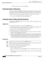
... LEDs: • Both Power LEDs should be green. • Bypass LED should immediately hear them operating. On the console terminal, after the system displays the system banner and hardware configuration, you should be green while the SCE 2000 is on...the following documents: • Cisco Service Control Engine (SCE) Software Configuration Guide • Cisco Service Control Engine (SCE) CLI Command Reference Starting the System and Observing Initial Conditions After installing your SCE 2000 platform hardware, checked all external connections, turned on position. During ...
... LEDs: • Both Power LEDs should be green. • Bypass LED should immediately hear them operating. On the console terminal, after the system displays the system banner and hardware configuration, you should be green while the SCE 2000 is on...the following documents: • Cisco Service Control Engine (SCE) Software Configuration Guide • Cisco Service Control Engine (SCE) CLI Command Reference Starting the System and Observing Initial Conditions After installing your SCE 2000 platform hardware, checked all external connections, turned on position. During ...

Configuration Guide
Page 111
...verify that the SCE 2000 is functioning properly are connected, verify that the SCE 2000 is not in a Warning state. • Examples for Verifying Operational Status SUMMARY STEPS 1. Compiled Tue 17-MAY-06 01:51 by Cisco Systems, Inc. To display the operation status of ...status LED to change from setup and using configuration commands to the following message appears: OL-7824-06 Cisco SCE 2000 4xGBE Installation and Configuration Guide 7-3 On the console terminal, after the system displays the system banner and hardware configuration, you for configuration information for a ...
...verify that the SCE 2000 is functioning properly are connected, verify that the SCE 2000 is not in a Warning state. • Examples for Verifying Operational Status SUMMARY STEPS 1. Compiled Tue 17-MAY-06 01:51 by Cisco Systems, Inc. To display the operation status of ...status LED to change from setup and using configuration commands to the following message appears: OL-7824-06 Cisco SCE 2000 4xGBE Installation and Configuration Guide 7-3 On the console terminal, after the system displays the system banner and hardware configuration, you for configuration information for a ...
Configuration Guide
Page 118
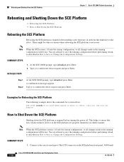
...made in the running configuration will be lost . At the SCE 2000# prompt, type reloadand press Enter. 2. A confirmation message appears. Connect to confirm the reboot request and press Enter. There might be lost . ythe system is about to reboot, this will be other occasions... where rebooting the SCE platform is necessary. SUMMARY STEPS 1. Type y to the serial console port (The CON connector on the SCE platform front panel, 9600 baud). 7-10 Cisco SCE 2000 4xGBE Installation and Configuration Guide OL-7824-06 SUMMARY STEPS 1. Examples for Rebooting the...
...made in the running configuration will be lost . At the SCE 2000# prompt, type reloadand press Enter. 2. A confirmation message appears. Connect to confirm the reboot request and press Enter. There might be lost . ythe system is about to reboot, this will be other occasions... where rebooting the SCE platform is necessary. SUMMARY STEPS 1. Type y to the serial console port (The CON connector on the SCE platform front panel, 9600 baud). 7-10 Cisco SCE 2000 4xGBE Installation and Configuration Guide OL-7824-06 SUMMARY STEPS 1. Examples for Rebooting the...

