Reference Guide
Page 22
... 1. You must assign a unique Unit ID (from 1 to 8) to a Running Stack 1. Assign each unit its front panel. Chapter 2 SGE2000/SGE2000P Gigabit Ethernet Switch Reference Guide Building Automatically-Configured Stacks Building a New Stack The easiest way to build a stack is to use a group of...Device Information Building Automatically-Configured Stacks Connect the units physically to the console port of the units selected as the Stack Master. Connect the units physically through the stacking ports, using standard Ethernet cables. 2. Power the units on . The unit selected as the Stack...
... 1. You must assign a unique Unit ID (from 1 to 8) to a Running Stack 1. Assign each unit its front panel. Chapter 2 SGE2000/SGE2000P Gigabit Ethernet Switch Reference Guide Building Automatically-Configured Stacks Building a New Stack The easiest way to build a stack is to use a group of...Device Information Building Automatically-Configured Stacks Connect the units physically to the console port of the units selected as the Stack Master. Connect the units physically through the stacking ports, using standard Ethernet cables. 2. Power the units on . The unit selected as the Stack...
Configuration Guide
Page 5
...25 How to Replace the Battery 4-26 Connecting the Management Interfaces and Performing Initial System Configuration 5-1 How to Set Up the Local Console 5-1 Initial System Configuration 5-3 Setup Command Parameters 5-4 Step 1: How to Configure Initial Settings 5-6 Step 2: How to Configure the Hostname...How to Cable the Management Port 5-25 How to Verify Management Interface Connectivity 5-26 Cabling the Line Ports and Completing the Installation 6-1 Connecting the line ports to the network 6-1 Cabling Diagrams 6-1 Single Link: Inline Topology 6-2 Single Link: Receive-only Topology 6-2 Cisco SCE ...
...25 How to Replace the Battery 4-26 Connecting the Management Interfaces and Performing Initial System Configuration 5-1 How to Set Up the Local Console 5-1 Initial System Configuration 5-3 Setup Command Parameters 5-4 Step 1: How to Configure Initial Settings 5-6 Step 2: How to Configure the Hostname...How to Cable the Management Port 5-25 How to Verify Management Interface Connectivity 5-26 Cabling the Line Ports and Completing the Installation 6-1 Connecting the line ports to the network 6-1 Cabling Diagrams 6-1 Single Link: Inline Topology 6-2 Single Link: Receive-only Topology 6-2 Cisco SCE ...

Configuration Guide
Page 10
...cabling the Gigabit Ethernet ports for both one and two SCE 2000 topologies, and for configuring Gigabit Ethernet (GBE) interface parameters. It also describes how to a local console and perform the initial system configuration via the setup wizard that runs automatically. Cisco...1 Chapter 2 Chapter 3 Chapter 4 Chapter 5 Chapter 6 Chapter 7 Title Description General Overview This chapter provides a brief introduction to Cisco Service Control. Information About Topology This chapter describes the possible deployment topologies of the SCE 2000 and explains how various aspects of the topology...
...cabling the Gigabit Ethernet ports for both one and two SCE 2000 topologies, and for configuring Gigabit Ethernet (GBE) interface parameters. It also describes how to a local console and perform the initial system configuration via the setup wizard that runs automatically. Cisco...1 Chapter 2 Chapter 3 Chapter 4 Chapter 5 Chapter 6 Chapter 7 Title Description General Overview This chapter provides a brief introduction to Cisco Service Control. Information About Topology This chapter describes the possible deployment topologies of the SCE 2000 and explains how various aspects of the topology...
Configuration Guide
Page 20
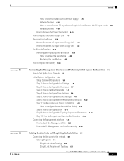
...GBE-1 SUB LINE NET Cisco S4CxEG2B0E00 LINK RX TX LINK RX TX RX MM TX RX MM TX GBE-2 SUB LINE/CASCADE NET Table 2-2 SCE 2000 Ports Port Mng1/ Mng2 Quantity 2 Console 1 Description Connect This Port To... 10/100/1000 Ethernet A LAN using an RS-232 cable with an RJ-45 ...management of the SCE connector. 2000 . RS-232 RJ-45 port for use by technicians A local terminal (console) using an FE RJ-45 ports for cable with an RJ-45 connector, as provided in the SCE 2000 kit. If both ports to provide a interface Management redundant management 0/1, 0/2. ...
...GBE-1 SUB LINE NET Cisco S4CxEG2B0E00 LINK RX TX LINK RX TX RX MM TX RX MM TX GBE-2 SUB LINE/CASCADE NET Table 2-2 SCE 2000 Ports Port Mng1/ Mng2 Quantity 2 Console 1 Description Connect This Port To... 10/100/1000 Ethernet A LAN using an RS-232 cable with an RJ-45 ...management of the SCE connector. 2000 . RS-232 RJ-45 port for use by technicians A local terminal (console) using an FE RJ-45 ports for cable with an RJ-45 connector, as provided in the SCE 2000 kit. If both ports to provide a interface Management redundant management 0/1, 0/2. ...

Configuration Guide
Page 25
... is completed, place it in rack (optional) AC/DC power cables connected to AC/DC sources and SCE 2000 platform Console port set for your installation and to console port FE management ports are operational GBE line and cascade ports operational OL-7824-06 Cisco SCE 2000 4xGBE Installation and Configuration Guide 2-7 Table 2-5 SCE...
... is completed, place it in rack (optional) AC/DC power cables connected to AC/DC sources and SCE 2000 platform Console port set for your installation and to console port FE management ports are operational GBE line and cascade ports operational OL-7824-06 Cisco SCE 2000 4xGBE Installation and Configuration Guide 2-7 Table 2-5 SCE...
Configuration Guide
Page 40
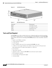
...• A new AC-input or DC-input power supply • A new fan module Cisco SCE 2000 4xGBE Installation and Configuration Guide 4-2 OL-7824-06 MNG 1 MNG 2 ALCITNIKV/E101/010000/ ALCITNIKV/E101/010000/ CONSOLE AUX PWR A PWR B STATUS BYPASS LINK RX TX LINK RX TX RX MM TX RX... leads Ring terminals must be UL approved and suitable for 12 AWG wire. • Level (optional) • Tape measure (optional) • Appropriate cables to connect the SCE 2000 to Install the SCE 2000 Platform Chapter 4 Installation and Maintenance Figure 4-1 SCE 2000 Dimensions 92776 1 3.47 in . 3 ...
...• A new AC-input or DC-input power supply • A new fan module Cisco SCE 2000 4xGBE Installation and Configuration Guide 4-2 OL-7824-06 MNG 1 MNG 2 ALCITNIKV/E101/010000/ ALCITNIKV/E101/010000/ CONSOLE AUX PWR A PWR B STATUS BYPASS LINK RX TX LINK RX TX RX MM TX RX... leads Ring terminals must be UL approved and suitable for 12 AWG wire. • Level (optional) • Tape measure (optional) • Appropriate cables to connect the SCE 2000 to Install the SCE 2000 Platform Chapter 4 Installation and Maintenance Figure 4-1 SCE 2000 Dimensions 92776 1 3.47 in . 3 ...

Configuration Guide
Page 43
... Flat Surface MNG 1 MNG 2 ALCITNIKV/E101/010000/ ALCITNIKV/E101/010000/ CONSOLE AUX PWR A PWR B STATUS BYPASS LINK RX TX RX MM TX LINK RX TX RX MM TX GBE-1 SUB LINE NET Cisco S4CxEG2B0E00 Series LINK RX TX LINK RX TX RX MM TX RX MM ... see Information About Site Requirement Guidelines and the Site Preparation and Safety Guide . How to Attach a Chassis Ground Connection for accessing network cables or equipment. • Ensure that accumulates on the floor during installation. Chapter 4 Installation and Maintenance Installing the SCE 2000 Platform Installation ...
... Flat Surface MNG 1 MNG 2 ALCITNIKV/E101/010000/ ALCITNIKV/E101/010000/ CONSOLE AUX PWR A PWR B STATUS BYPASS LINK RX TX RX MM TX LINK RX TX RX MM TX GBE-1 SUB LINE NET Cisco S4CxEG2B0E00 Series LINK RX TX LINK RX TX RX MM TX RX MM ... see Information About Site Requirement Guidelines and the Site Preparation and Safety Guide . How to Attach a Chassis Ground Connection for accessing network cables or equipment. • Ensure that accumulates on the floor during installation. Chapter 4 Installation and Maintenance Installing the SCE 2000 Platform Installation ...

Configuration Guide
Page 65
...if you will run automatically, prompting you must first connect the unit to a local console and configure the initial settings for cabling the Fast Ethernet Management interfaces. Figure 5-1 Connecting the Local Console to a local console and perform the initial system configuration via the setup wizard that runs automatically. When the... Series LINK RX TX LINK RX TX RX MM TX RX MM TX GBE-2 SUB LINE/CASCADE NET OL-7824-06 Cisco SCE 2000 4xGBE Installation and Configuration Guide 5-1 Note When installing a cascaded system, it is established, the setup utility will be managing ...
...if you will run automatically, prompting you must first connect the unit to a local console and configure the initial settings for cabling the Fast Ethernet Management interfaces. Figure 5-1 Connecting the Local Console to a local console and perform the initial system configuration via the setup wizard that runs automatically. When the... Series LINK RX TX LINK RX TX RX MM TX RX MM TX GBE-2 SUB LINE/CASCADE NET OL-7824-06 Cisco SCE 2000 4xGBE Installation and Configuration Guide 5-1 Note When installing a cascaded system, it is established, the setup utility will be managing ...

Configuration Guide
Page 66
... 2000 CON port parameters. 4. Make sure the local terminal is configured as a VT-100 terminal, according to Set Up the Local Console Chapter 5 Connecting the Management Interfaces and Performing Initial System Configuration Make sure that the terminal configuration is locked into the CON port on ... may enter a question mark '?' followed by 'Enter' for help. Connect the other end of the serial cable (with an attached DB-9 connector) to the RS-232 serial cable) until the Cisco logo appears on the plug to the VT100 compatible local (serial) terminal. 3. Make sure that the connector...
... 2000 CON port parameters. 4. Make sure the local terminal is configured as a VT-100 terminal, according to Set Up the Local Console Chapter 5 Connecting the Management Interfaces and Performing Initial System Configuration Make sure that the terminal configuration is locked into the CON port on ... may enter a question mark '?' followed by 'Enter' for help. Connect the other end of the serial cable (with an attached DB-9 connector) to the RS-232 serial cable) until the Cisco logo appears on the plug to the VT100 compatible local (serial) terminal. 3. Make sure that the connector...

Configuration Guide
Page 89
...The two management ports provide the possibility for cabling the management port and testing connectivity between the SCE 2000 and the remote management host are you like to the management console via a LAN. OL-7824-06 Cisco SCE 2000 4xGBE Installation and Configuration Guide 5-...25 These ports provide access from a remote management console to the startup configuration. Would you sure? [yes/no]:ySetup procedure...
...The two management ports provide the possibility for cabling the management port and testing connectivity between the SCE 2000 and the remote management host are you like to the management console via a LAN. OL-7824-06 Cisco SCE 2000 4xGBE Installation and Configuration Guide 5-...25 These ports provide access from a remote management console to the startup configuration. Would you sure? [yes/no]:ySetup procedure...

Configuration Guide
Page 90
... management port Link LED on the front panel of the plug, releasing the latch. Test connectivity. Figure 5-2 Cabling the Management Port 92791 12 MNG 1 MNG 2 ALCITNIKV/E101/010000/ ALCITNIKV/E101/010000/ CONSOLE AUX 3 PWR A PWR B STATUS BYPASS LINK RX TX LINK RX TX RX MM TX RX MM TX.... How to the SCE 2000 by typing ping and the SCE 2000 IP address, and pressing Enter (see the example, below). 5-26 Cisco SCE 2000 4xGBE Installation and Configuration Guide OL-7824-06 SUMMARY STEPS 1. After you intend to use for remote management, ping to Verify Management...
... management port Link LED on the front panel of the plug, releasing the latch. Test connectivity. Figure 5-2 Cabling the Management Port 92791 12 MNG 1 MNG 2 ALCITNIKV/E101/010000/ ALCITNIKV/E101/010000/ CONSOLE AUX 3 PWR A PWR B STATUS BYPASS LINK RX TX LINK RX TX RX MM TX RX MM TX.... How to the SCE 2000 by typing ping and the SCE 2000 IP address, and pressing Enter (see the example, below). 5-26 Cisco SCE 2000 4xGBE Installation and Configuration Guide OL-7824-06 SUMMARY STEPS 1. After you intend to use for remote management, ping to Verify Management...

Configuration Guide
Page 101
...indicate that packets are the sole indicators. Chapter 6 Cabling the Line Ports and Completing the Installation Figure 6-6 Cabling the GBE Interface Connecting the line ports to the network 92783 MNG 1 MNG 2 ALCITNIKV/E1100/10000/ ALCITNIKV/E1100/10000/ CONSOLE AUX PWR A PWR B STATUS BYPASS LINK RX ...TX LINK RX TX RX MM TX RX MM TX GBE-1 SUB LINE NET Cisco S4CxEG2B0E00 Series...
...indicate that packets are the sole indicators. Chapter 6 Cabling the Line Ports and Completing the Installation Figure 6-6 Cabling the GBE Interface Connecting the line ports to the network 92783 MNG 1 MNG 2 ALCITNIKV/E1100/10000/ ALCITNIKV/E1100/10000/ CONSOLE AUX PWR A PWR B STATUS BYPASS LINK RX ...TX LINK RX TX RX MM TX RX MM TX GBE-1 SUB LINE NET Cisco S4CxEG2B0E00 Series...

Configuration Guide
Page 109
... is connected to at installation: - SCE 2000 platform connected to local console (CON port) OL-7824-06 Cisco SCE 2000 4xGBE Installation and Configuration Guide 7-1 Direct connection to local console (CON port) - Line and Cascade interfaces are properly cabled (optional) - It also describes how to manage configurations. • Starting the SCE 2000 Platform •...
... is connected to at installation: - SCE 2000 platform connected to local console (CON port) OL-7824-06 Cisco SCE 2000 4xGBE Installation and Configuration Guide 7-1 Direct connection to local console (CON port) - Line and Cascade interfaces are properly cabled (optional) - It also describes how to manage configurations. • Starting the SCE 2000 Platform •...
Configuration Guide
Page 110
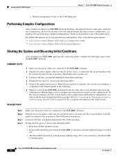
Listen for the fans; Observe the initialization process. When the system boot is flashing green. Cisco SCE 2000 4xGBE Installation and Configuration Guide 7-2 OL-7824-06 Starting the SCE 2000 Platform Chapter 7 Basic SCE 2000 Platform .... During the boot process, observe the following LEDs: 5. Make sure the power cables are turned to Connecting the Management Interfaces and Performing Initial System Configuration for initial system configuration. On the console terminal, after the system displays the system banner and hardware configuration, you should immediately...
Listen for the fans; Observe the initialization process. When the system boot is flashing green. Cisco SCE 2000 4xGBE Installation and Configuration Guide 7-2 OL-7824-06 Starting the SCE 2000 Platform Chapter 7 Basic SCE 2000 Platform .... During the boot process, observe the following LEDs: 5. Make sure the power cables are turned to Connecting the Management Interfaces and Performing Initial System Configuration for initial system configuration. On the console terminal, after the system displays the system banner and hardware configuration, you should immediately...

Configuration Guide
Page 127
... on . Table 8-4 Troubleshooting the Power Subsystem Symptom Possible Cause Power LED on the front panel and LEDs on the console screen. OL-7824-06 Cisco SCE 2000 4xGBE Installation and Configuration Guide 8-7 Possible Solution Turn the power switch to another power source, if available, ...and turn the SCE 2000 platform off position and reseat the power cable at least one of the following to the console port. •...
... on . Table 8-4 Troubleshooting the Power Subsystem Symptom Possible Cause Power LED on the front panel and LEDs on the console screen. OL-7824-06 Cisco SCE 2000 4xGBE Installation and Configuration Guide 8-7 Possible Solution Turn the power switch to another power source, if available, ...and turn the SCE 2000 platform off position and reseat the power cable at least one of the following to the console port. •...

