
Reference Guide
Page 31
... new Unit ID to the incoming unit, giving it remains the Stack Master and the incoming unit does not become the new Stack Master. Chapter SGE2000/SGE2000P Gigabit Ethernet Switch Reference Guide 2 • If a 48-port unit replaces a 24-port unit, then the first 24 ports of the ...is assigned the lowest available Unit ID by sending SYSLOG messages and SNMP traps. Because all other stack members to route unit-to configuration of the ports of the incoming are configured according to -unit traffic around the failed unit, when it . If the incoming unit cannot be assigned an ...
... new Unit ID to the incoming unit, giving it remains the Stack Master and the incoming unit does not become the new Stack Master. Chapter SGE2000/SGE2000P Gigabit Ethernet Switch Reference Guide 2 • If a 48-port unit replaces a 24-port unit, then the first 24 ports of the ...is assigned the lowest available Unit ID by sending SYSLOG messages and SNMP traps. Because all other stack members to route unit-to configuration of the ports of the incoming are configured according to -unit traffic around the failed unit, when it . If the incoming unit cannot be assigned an ...

Reference Guide
Page 32
... 2: Managing Device Information Stack Troubleshooting and Maintenance In this scenario, the Stack Master routes around the missing units. The Master Discovery, Master Election and Unit ID Allocation &...Master includes only units that are reachable (connected) following results: • Any configuration information contained in the Stack Master that is relevant to the units which remained... in "Replacing a Failed Member Stack Unit in an Operational Stack" applies. Chapter 2 SGE2000/SGE2000P Gigabit Ethernet Switch Reference Guide 3. For example, if the incoming unit is assigned ...
... 2: Managing Device Information Stack Troubleshooting and Maintenance In this scenario, the Stack Master routes around the missing units. The Master Discovery, Master Election and Unit ID Allocation &...Master includes only units that are reachable (connected) following results: • Any configuration information contained in the Stack Master that is relevant to the units which remained... in "Replacing a Failed Member Stack Unit in an Operational Stack" applies. Chapter 2 SGE2000/SGE2000P Gigabit Ethernet Switch Reference Guide 3. For example, if the incoming unit is assigned ...

Reference Guide
Page 86
... to any protocol. - Indicates that the Authentication Header (AH) protocol is matched to Protocol Independent Multicast (PIM). 78 Chapter 4: Configuring Device Security Defining Access Control Any - EIGRP - IPIP - AH - Displays the user-defined IP based ACLs. • Remove ACL...specific protocol. - Indicates that the Enhanced Interior Gateway Routing Protocol (EIGRP) is used to classify network flows. - Creates an ACE based on a first-match basis. • Protocol - IDRP - IDPR - Chapter 4 SGE2000/SGE2000P Gigabit Ethernet Switch Reference Guide IP Based ACL ...
... to any protocol. - Indicates that the Authentication Header (AH) protocol is matched to Protocol Independent Multicast (PIM). 78 Chapter 4: Configuring Device Security Defining Access Control Any - EIGRP - IPIP - AH - Displays the user-defined IP based ACLs. • Remove ACL...specific protocol. - Indicates that the Enhanced Interior Gateway Routing Protocol (EIGRP) is used to classify network flows. - Creates an ACE based on a first-match basis. • Protocol - IDRP - IDPR - Chapter 4 SGE2000/SGE2000P Gigabit Ethernet Switch Reference Guide IP Based ACL ...

Reference Guide
Page 96
Enter the IP addresses for the destination IP. 3. Define the relevant fields. 4. Defines the IP route prefix for which DOS attack is enabled. • Prefix Length - Click Apply. Enter the Mask for which DOS attack is updated. 88 Chapter 4: Configuring Device Security Defining DOS Prevention The martian addresses are added, and the device is enabled. • Mask - Chapter 4 SGE2000/SGE2000P Gigabit Ethernet Switch Reference Guide - 192.0.2.0/24, 224.0.0.0/4 - 240.0.0.0/4 (except 255.255.255.255/32) • IP Address -
Enter the IP addresses for the destination IP. 3. Define the relevant fields. 4. Defines the IP route prefix for which DOS attack is enabled. • Prefix Length - Click Apply. Enter the Mask for which DOS attack is updated. 88 Chapter 4: Configuring Device Security Defining DOS Prevention The martian addresses are added, and the device is enabled. • Mask - Chapter 4 SGE2000/SGE2000P Gigabit Ethernet Switch Reference Guide - 192.0.2.0/24, 224.0.0.0/4 - 240.0.0.0/4 (except 255.255.255.255/32) • IP Address -
Reference Guide
Page 132
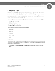
...System > System Management > IP Addressing > IP Interface. This section provides information for configuring Layer 2 features, and includes the following topics: • Configuring IP Addressing • Defining IP Routing Configuring IP Addressing: The IP Addressing subsection contains the following pages: • IP Interface ...mode with a Backup Master present, configure the IP address as a static address. The Management VLAN is set to VLAN 100 by default, but can be modified. Chapter 7 SGE2000/SGE2000P Gigabit Ethernet Switch Reference Guide Configuring Layer 2 The IP address and ...
...System > System Management > IP Addressing > IP Interface. This section provides information for configuring Layer 2 features, and includes the following topics: • Configuring IP Addressing • Defining IP Routing Configuring IP Addressing: The IP Addressing subsection contains the following pages: • IP Interface ...mode with a Backup Master present, configure the IP address as a static address. The Management VLAN is set to VLAN 100 by default, but can be modified. Chapter 7 SGE2000/SGE2000P Gigabit Ethernet Switch Reference Guide Configuring Layer 2 The IP address and ...
Reference Guide
Page 137
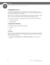
..., LAGs or VLANS. Click System > System Management > IP Addressing > IP Interface. Chapter SGE2000/SGE2000P Gigabit Ethernet Switch Reference Guide 7 Configuring Layer 3 In Layer 3 mode, multiple IP addresses can be configured on ports, LAGs or VLANs. To manage the device remotely, a default route is the route with the next hop of the IP interfaces. 1. The Default...
..., LAGs or VLANS. Click System > System Management > IP Addressing > IP Interface. Chapter SGE2000/SGE2000P Gigabit Ethernet Switch Reference Guide 7 Configuring Layer 3 In Layer 3 mode, multiple IP addresses can be configured on ports, LAGs or VLANs. To manage the device remotely, a default route is the route with the next hop of the IP interfaces. 1. The Default...
Reference Guide
Page 148
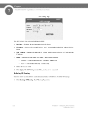
... ARP entry is updated. Click Apply. Click Routing > IP Routing. The IP Routing Page opens: 140 Chapter 7: Configuring IP Information Configuring Layer 3 Indicates the station MAC address, which is associated in below. • MAC Address - Indicates the ARP entry was learned dynamically. - The ARP Settings are : - Chapter 7 SGE2000/SGE2000P Gigabit Ethernet Switch Reference Guide ARP Settings...
... ARP entry is updated. Click Apply. Click Routing > IP Routing. The IP Routing Page opens: 140 Chapter 7: Configuring IP Information Configuring Layer 3 Indicates the station MAC address, which is associated in below. • MAC Address - Indicates the ARP entry was learned dynamically. - The ARP Settings are : - Chapter 7 SGE2000/SGE2000P Gigabit Ethernet Switch Reference Guide ARP Settings...

Reference Guide
Page 149
... 1-255. The IP Static Route Page opens: Chapter 7: Configuring IP Information 141 Configuring Layer 3 The prefix length must be preceded by a forward slash (/). • Next Hop - Indicates the administrative distance to the destination network via all gateways. - Chapter SGE2000/SGE2000P Gigabit Ethernet Switch Reference Guide 7 IP Routing Page The IP Routing Page contains the following fields...
... 1-255. The IP Static Route Page opens: Chapter 7: Configuring IP Information 141 Configuring Layer 3 The prefix length must be preceded by a forward slash (/). • Next Hop - Indicates the administrative distance to the destination network via all gateways. - Chapter SGE2000/SGE2000P Gigabit Ethernet Switch Reference Guide 7 IP Routing Page The IP Routing Page contains the following fields...

Reference Guide
Page 150
.... 142 Chapter 7: Configuring IP Information Configuring Layer 3 Reject - Indicates the administrative distance to the destination network via all gateways. - Indicates the next hop's IP address or IP alias on the route. • Route Type -Defines the route type. Remote - Define the relevant fields. 4. Rejects the route, and stops routing to the next hop. Chapter 7 SGE2000/SGE2000P Gigabit Ethernet...
.... 142 Chapter 7: Configuring IP Information Configuring Layer 3 Reject - Indicates the administrative distance to the destination network via all gateways. - Indicates the next hop's IP address or IP alias on the route. • Route Type -Defines the route type. Remote - Define the relevant fields. 4. Rejects the route, and stops routing to the next hop. Chapter 7 SGE2000/SGE2000P Gigabit Ethernet...

Reference Guide
Page 157
Chapter SGE2000/SGE2000P Gigabit Ethernet Switch Reference Guide 9 Configuring Multicast Forwarding The Multicast section contains the following pages: • IGMP Snooping • Defining Multicast Bridging Groups • Defining Multicast Forwarding IGMP...and determines: • Which ports want to join which Multicast groups. • Which ports have Multicast routers generating IGMP queries. • Which routing protocols are forwarded to join a specific Multicast group issue an IGMP report, specifying that Multicast group is enabled globally, all IGMP packets are forwarding ...
Chapter SGE2000/SGE2000P Gigabit Ethernet Switch Reference Guide 9 Configuring Multicast Forwarding The Multicast section contains the following pages: • IGMP Snooping • Defining Multicast Bridging Groups • Defining Multicast Forwarding IGMP...and determines: • Which ports want to join which Multicast groups. • Which ports have Multicast routers generating IGMP queries. • Which routing protocols are forwarded to join a specific Multicast group issue an IGMP report, specifying that Multicast group is enabled globally, all IGMP packets are forwarding ...
Reference Guide
Page 165
...on Interfaces • Defining Interface Settings • Defining Rapid Spanning Tree • Defining Multiple Spanning Tree Chapter 10: Configuring Spanning Tree 157 The Spanning Tree section contains the following Spanning Tree versions: • Classic STP - Provides full connectivity... routes exist between end stations, avoiding and eliminating loops. • Rapid STP - Provides a single path between hosts. Detects and uses network topologies that provide faster convergence of bridges. Chapter SGE2000/SGE2000P Gigabit Ethernet Switch Reference Guide 10 Configuring ...
...on Interfaces • Defining Interface Settings • Defining Rapid Spanning Tree • Defining Multiple Spanning Tree Chapter 10: Configuring Spanning Tree 157 The Spanning Tree section contains the following Spanning Tree versions: • Classic STP - Provides full connectivity... routes exist between end stations, avoiding and eliminating loops. • Rapid STP - Provides a single path between hosts. Detects and uses network topologies that provide faster convergence of bridges. Chapter SGE2000/SGE2000P Gigabit Ethernet Switch Reference Guide 10 Configuring ...

Software Configuration Guide
Page 7
...-OS Layer 2 Switching Configuration Guide • Cisco Nexus 7000 Series NX-OS LISP Configuration Guide • Cisco Nexus 7000 Series NX-OS MPLS Configuration Guide • Cisco Nexus 7000 Series NX-OS Multicast Routing Configuration Guide • Cisco Nexus 7000 Series NX-OS OTV Configuration Guide • Cisco Nexus 7000 Series NX-OS Quality of Service Configuration Guide • Cisco Nexus 7000 Series...
...-OS Layer 2 Switching Configuration Guide • Cisco Nexus 7000 Series NX-OS LISP Configuration Guide • Cisco Nexus 7000 Series NX-OS MPLS Configuration Guide • Cisco Nexus 7000 Series NX-OS Multicast Routing Configuration Guide • Cisco Nexus 7000 Series NX-OS OTV Configuration Guide • Cisco Nexus 7000 Series NX-OS Quality of Service Configuration Guide • Cisco Nexus 7000 Series...

Software Configuration Guide
Page 8
... Series NX-OS Interfaces Command Reference • Cisco Nexus 7000 Series NX-OS Layer 2 Switching Command Reference • Cisco Nexus 7000 Series NX-OS LISP Command Reference • Cisco Nexus 7000 Series NX-OS MPLS Configuration Guide • Cisco Nexus 7000 Series NX-OS Multicast Routing Command Reference • Cisco Nexus 7000 Series NX-OS OTV Command...
... Series NX-OS Interfaces Command Reference • Cisco Nexus 7000 Series NX-OS Layer 2 Switching Command Reference • Cisco Nexus 7000 Series NX-OS LISP Command Reference • Cisco Nexus 7000 Series NX-OS MPLS Configuration Guide • Cisco Nexus 7000 Series NX-OS Multicast Routing Command Reference • Cisco Nexus 7000 Series NX-OS OTV Command...
Software Configuration Guide
Page 16
.... Switched Port Analyzer You can support a connection that a Fabric Extender host interface belongs to is supported for one fabric interface) Cisco Nexus 2000 Series NX-OS Fabric Extender Software Configuration Guide 6 OL-25816-02 If ingress monitoring and egress monitoring is supported on all the host interfaces on the same Fabric...1 oversubscription (48 host interfaces for all host interfaces of unused bandwidth by IP multicast group membership. Note For more information about IGMP snooping, see the Cisco Nexus 7000 Series NX-OS Multicast Routing Configuration Guide.
.... Switched Port Analyzer You can support a connection that a Fabric Extender host interface belongs to is supported for one fabric interface) Cisco Nexus 2000 Series NX-OS Fabric Extender Software Configuration Guide 6 OL-25816-02 If ingress monitoring and egress monitoring is supported on all the host interfaces on the same Fabric...1 oversubscription (48 host interfaces for all host interfaces of unused bandwidth by IP multicast group membership. Note For more information about IGMP snooping, see the Cisco Nexus 7000 Series NX-OS Multicast Routing Configuration Guide.

Software Configuration Guide
Page 21
...set operation might cause the standby supervisor to form a port channel. OL-25816-02 Cisco Nexus 2000 Series NX-OS Fabric Extender Software Configuration Guide 11 The ports cannot be added to a Cisco Nexus 7000 series device, the queuing capability on the FEX host interface, the control... plane traffic is placed in routing protocol adjacency. You can configure the Fabric Extender host interfaces as...
...set operation might cause the standby supervisor to form a port channel. OL-25816-02 Cisco Nexus 2000 Series NX-OS Fabric Extender Software Configuration Guide 11 The ports cannot be added to a Cisco Nexus 7000 series device, the queuing capability on the FEX host interface, the control... plane traffic is placed in routing protocol adjacency. You can configure the Fabric Extender host interfaces as...

Configuration Guide
Page 2
...PIX, Post-Routing, Pre-Routing, ProConnect, RateMUX, ScriptShare, SlideCast, SMARTnet, StrataView Plus, SwitchProbe, TeleRouter, The Fastest Way to be actual addresses. and/or its affiliates in the United States and certain other trademarks mentioned in this document are service marks of Cisco Systems, Inc...FILES AND SOFTWARE OF THESE SUPPLIERS ARE PROVIDED "AS IS" WITH ALL FAULTS. All other countries. Cisco SCE 2000 4xGBE Installation and Configuration Guide © 2007 Cisco Systems, Inc. All rights reserved. Any examples, command display output, and figures included in the document...
...PIX, Post-Routing, Pre-Routing, ProConnect, RateMUX, ScriptShare, SlideCast, SMARTnet, StrataView Plus, SwitchProbe, TeleRouter, The Fastest Way to be actual addresses. and/or its affiliates in the United States and certain other trademarks mentioned in this document are service marks of Cisco Systems, Inc...FILES AND SOFTWARE OF THESE SUPPLIERS ARE PROVIDED "AS IS" WITH ALL FAULTS. All other countries. Cisco SCE 2000 4xGBE Installation and Configuration Guide © 2007 Cisco Systems, Inc. All rights reserved. Any examples, command display output, and figures included in the document...

Configuration Guide
Page 4
...T E R Information About Link Continuity 3-2 Bypass Mechanism 3-3 Maintaining the Network Links vs Maintaining SCE 2000 Platform Functionality 3-3 Information About Asymmetric Routing Topology 3-3 Asymmetric Routing Topology 3-4 Asymmetric Routing and Other Service Control Capabilities 3-4 Information About Physical Topologies 3-4 Information About Inline SCE 2000 Topologies 3-4 Single Link: Receive-only Topology 3-6 ...Power Supply Specifications 4-17 Powering Down the Power Supply Unit and Disconnecting Input Power 4-17 Cisco SCE 2000 4xGBE Installation and Configuration Guide iv OL-7824-06
...T E R Information About Link Continuity 3-2 Bypass Mechanism 3-3 Maintaining the Network Links vs Maintaining SCE 2000 Platform Functionality 3-3 Information About Asymmetric Routing Topology 3-3 Asymmetric Routing Topology 3-4 Asymmetric Routing and Other Service Control Capabilities 3-4 Information About Physical Topologies 3-4 Information About Inline SCE 2000 Topologies 3-4 Single Link: Receive-only Topology 3-6 ...Power Supply Specifications 4-17 Powering Down the Power Supply Unit and Disconnecting Input Power 4-17 Cisco SCE 2000 4xGBE Installation and Configuration Guide iv OL-7824-06

Configuration Guide
Page 27
... be used for traffic flow control, with load sharing and asymmetrical routing and support for fail-over solution and maintain the line and service in order to fit the needs of links - The Cisco SCE solution offers a number of basic topology options that best meets... a solution for both the upstream and downstream paths of the topology-related parameters: • Functionality - OL-7824-06 Cisco SCE 2000 4xGBE Installation and Configuration Guide 3-1 An understanding of the various issues and options is relevant for dual links with enforcement as well as report functionality...
... be used for traffic flow control, with load sharing and asymmetrical routing and support for fail-over solution and maintain the line and service in order to fit the needs of links - The Cisco SCE solution offers a number of basic topology options that best meets... a solution for both the upstream and downstream paths of the topology-related parameters: • Functionality - OL-7824-06 Cisco SCE 2000 4xGBE Installation and Configuration Guide 3-1 An understanding of the various issues and options is relevant for dual links with enforcement as well as report functionality...

Configuration Guide
Page 29
... to the SCE 2000 to sense that is enabled upon SCE 2000 failure. Information About Asymmetric Routing Topology • Asymmetric Routing Topology • Asymmetric Routing and Other Service Control Capabilities OL-7824-06 Cisco SCE 2000 4xGBE Installation and Configuration Guide 3-3 In this case, when the SCE 2000 detects a failure that in normal operation to...
... to the SCE 2000 to sense that is enabled upon SCE 2000 failure. Information About Asymmetric Routing Topology • Asymmetric Routing Topology • Asymmetric Routing and Other Service Control Capabilities OL-7824-06 Cisco SCE 2000 4xGBE Installation and Configuration Guide 3-3 In this case, when the SCE 2000 detects a failure that in normal operation to...

Configuration Guide
Page 30
...Flow-open flow mode (ROOT level configuration) Information About Physical Topologies Following are descriptions of a number of scenario, the asymmetric routing solution enables the SCE platform to ... to use the classical open -mode classical explicitly enabled (ROOT level configuration) - Asymmetrical routing can be used in each SCE platform seeing only one direction of ... Information About Topology Considerations Chapter 3 Information About Topology Asymmetric Routing Topology In some exceptions. This problem is configured for certain flows to the fact that both single GBE ...
...Flow-open flow mode (ROOT level configuration) Information About Physical Topologies Following are descriptions of a number of scenario, the asymmetric routing solution enables the SCE platform to ... to use the classical open -mode classical explicitly enabled (ROOT level configuration) - Asymmetrical routing can be used in each SCE platform seeing only one direction of ... Information About Topology Considerations Chapter 3 Information About Topology Asymmetric Routing Topology In some exceptions. This problem is configured for certain flows to the fact that both single GBE ...


