Specifications
Page 2
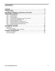
... DETAILED VIEWS 4 Chassis Front View 4 BASE SERVER STANDARD CAPABILITIES and FEATURES 5 CONFIGURING the SERVER 6 STEP 1 VERIFY BASE SKU 7 STEP 2 CHOOSE CPU(S 8 STEP 3 CHOOSE MEMORY 10 STEP 4 CHOOSE HARD DISK DRIVES or SOLID STATE DRIVES 14 STEP 5 CHOOSE A PCIe MEZZANINE CARD 15 STEP 6 ...SOFTWARE 20 STEP 9 CHOOSE SERVICE and SUPPORT LEVEL 21 ORDER OPTIONAL KVM CABLE 25 SUPPLEMENTAL MATERIAL 26 Motherboard 26 DIMM and CPU Layout 26 Memory Population Recommendations 27 TECHNICAL SPECIFICATIONS 29 Dimensions and Weight 29 Power Specifications 29 Cisco UCS B200 M2 Blade Server 2
... DETAILED VIEWS 4 Chassis Front View 4 BASE SERVER STANDARD CAPABILITIES and FEATURES 5 CONFIGURING the SERVER 6 STEP 1 VERIFY BASE SKU 7 STEP 2 CHOOSE CPU(S 8 STEP 3 CHOOSE MEMORY 10 STEP 4 CHOOSE HARD DISK DRIVES or SOLID STATE DRIVES 14 STEP 5 CHOOSE A PCIe MEZZANINE CARD 15 STEP 6 ...SOFTWARE 20 STEP 9 CHOOSE SERVICE and SUPPORT LEVEL 21 ORDER OPTIONAL KVM CABLE 25 SUPPLEMENTAL MATERIAL 26 Motherboard 26 DIMM and CPU Layout 26 Memory Population Recommendations 27 TECHNICAL SPECIFICATIONS 29 Dimensions and Weight 29 Power Specifications 29 Cisco UCS B200 M2 Blade Server 2

Specifications
Page 3
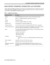
Figure 1 Cisco UCS B200 M2 Blade Server Cisco UCS B200 M2 Blade Server 3 OVERVIEW OVERVIEW The Cisco UCS B200 M2 Blade Server (Figure 1) Server is a two-socket, half-width blade server, using Intel's Xeon 5500 and 5600 Series processors with 12 DIMM slots, one mezzanine slot to hold an adapter card, and up to eight half-width blade servers can be accommodated in the Cisco UCS 5108 Blade Server Chassis. Up to two solid-state disk (SSD) drives or hard disk drives (HDDs).
Figure 1 Cisco UCS B200 M2 Blade Server Cisco UCS B200 M2 Blade Server 3 OVERVIEW OVERVIEW The Cisco UCS B200 M2 Blade Server (Figure 1) Server is a two-socket, half-width blade server, using Intel's Xeon 5500 and 5600 Series processors with 12 DIMM slots, one mezzanine slot to hold an adapter card, and up to eight half-width blade servers can be accommodated in the Cisco UCS 5108 Blade Server Chassis. Up to two solid-state disk (SSD) drives or hard disk drives (HDDs).

Specifications
Page 4
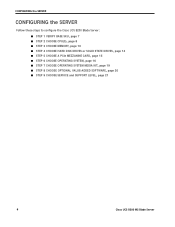
.... 4 Cisco UCS B200 M2 Blade Server Figure 2 Chassis Front View 4 5 1 2 3 6 78 9 10 11 1 Asset tag (you can remove this tag and 7 Network link status LED add your own) 2 Blade ejector handle 8 Blade health LED 3 Blade ejector handle captive screw 9 Console connector1 4 Drive bay 1 (hot pluggable) 10 Reset button access 5 Drive bay 2 (hot pluggable) 11 Beaconing LED and button 6 Power button and LED Notes...
.... 4 Cisco UCS B200 M2 Blade Server Figure 2 Chassis Front View 4 5 1 2 3 6 78 9 10 11 1 Asset tag (you can remove this tag and 7 Network link status LED add your own) 2 Blade ejector handle 8 Blade health LED 3 Blade ejector handle captive screw 9 Console connector1 4 Drive bay 1 (hot pluggable) 10 Reset button access 5 Drive bay 2 (hot pluggable) 11 Beaconing LED and button 6 Power button and LED Notes...
Specifications
Page 5
... core. Details about how to configure the server for a particular feature or capability (for registered DIMMs (up to 192 GB) Accommodates one mezzanine adapter card LSI Logic 1064e controller and integrated RAID (RAID 0 and 1 supported) Up to the video core. ■ 1280 x 1024 resolution ■ 32-bit color depth ■ 8 MB video memory ■ Front panel • One console connector...
... core. Details about how to configure the server for a particular feature or capability (for registered DIMMs (up to 192 GB) Accommodates one mezzanine adapter card LSI Logic 1064e controller and integrated RAID (RAID 0 and 1 supported) Up to the video core. ■ 1280 x 1024 resolution ■ 32-bit color depth ■ 8 MB video memory ■ Front panel • One console connector...
Specifications
Page 6
CONFIGURING the SERVER CONFIGURING the SERVER Follow these steps to configure the Cisco UCS B200 Blade Server: ■ STEP 1 VERIFY BASE SKU, page 7 ■ STEP 2 CHOOSE CPU(S), page 8 ■ STEP 3 CHOOSE MEMORY, page 10 ■ STEP 4 CHOOSE HARD DISK DRIVES or SOLID STATE DRIVES, page 14 ■ STEP 5 CHOOSE A PCIe MEZZANINE CARD, page 15 ■ STEP 6 CHOOSE OPERATING SYSTEM, page 16 ■ STEP 7 CHOOSE...
CONFIGURING the SERVER CONFIGURING the SERVER Follow these steps to configure the Cisco UCS B200 Blade Server: ■ STEP 1 VERIFY BASE SKU, page 7 ■ STEP 2 CHOOSE CPU(S), page 8 ■ STEP 3 CHOOSE MEMORY, page 10 ■ STEP 4 CHOOSE HARD DISK DRIVES or SOLID STATE DRIVES, page 14 ■ STEP 5 CHOOSE A PCIe MEZZANINE CARD, page 15 ■ STEP 6 CHOOSE OPERATING SYSTEM, page 16 ■ STEP 7 CHOOSE...
Specifications
Page 7
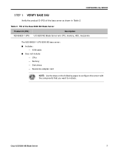
KVM cable ■ Does not include: - CPUs - Mezzanine adapter card NOTE: Use the steps on the following pages to configure the server with the components that you want to include. Disk drives - Cisco UCS B200 M2 Blade Server 7 Table 2 PID of the base server as shown in Table 2. Memory - CONFIGURING the SERVER STEP 1 VERIFY BASE SKU Verify the product ID (PID) of the Base B200 M2 Blade Server Product ID (PID) Description N20-B6625-1-UPG UCS B200 M2 Blade Server w/o CPU, memory, HDD, mezzanine The N20-B6625-1-UPG B200 M2 base server: ■ Includes: -
KVM cable ■ Does not include: - CPUs - Mezzanine adapter card NOTE: Use the steps on the following pages to configure the server with the components that you want to include. Disk drives - Cisco UCS B200 M2 Blade Server 7 Table 2 PID of the base server as shown in Table 2. Memory - CONFIGURING the SERVER STEP 1 VERIFY BASE SKU Verify the product ID (PID) of the Base B200 M2 Blade Server Product ID (PID) Description N20-B6625-1-UPG UCS B200 M2 Blade Server w/o CPU, memory, HDD, mezzanine The N20-B6625-1-UPG B200 M2 base server: ■ Includes: -

Specifications
Page 8
CONFIGURING the SERVER STEP 2 CHOOSE CPU(S) The standard CPU features are: ■ Intel Xeon 5600-series (Westmere-EP) or 5500-series (Nehalem) CPUs ■ Intel 5500 chipset ■ Cache size of 1066 MHz. Table 3 Available Intel CPUs: Xeon Westmere-EP x56xx Family Product ID (PID) Intel Number UCS-CPU-X5687 A01-X0115 ...: If you use an X5650 CPU (which can support up to 1333-MHz DIMMs) with an E5620 (which can support up to 1066-MHz DIMMs), the DIMMS will be clocked at the lowest common denominator of 1066 MHz. 8 Cisco UCS B200 M2 Blade Server If higher or lower speed DIMMs...
CONFIGURING the SERVER STEP 2 CHOOSE CPU(S) The standard CPU features are: ■ Intel Xeon 5600-series (Westmere-EP) or 5500-series (Nehalem) CPUs ■ Intel 5500 chipset ■ Cache size of 1066 MHz. Table 3 Available Intel CPUs: Xeon Westmere-EP x56xx Family Product ID (PID) Intel Number UCS-CPU-X5687 A01-X0115 ...: If you use an X5650 CPU (which can support up to 1333-MHz DIMMs) with an E5620 (which can support up to 1066-MHz DIMMs), the DIMMS will be clocked at the lowest common denominator of 1066 MHz. 8 Cisco UCS B200 M2 Blade Server If higher or lower speed DIMMs...
Specifications
Page 9
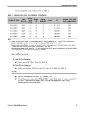
... clocked at the lower speed of CPU clock and DIMM clock. Table 4 Available Intel CPUs: Xeon Nehalem x55xx Family Product ID (PID) Intel Number Clock Freq (GHz) Power (W) Cache Size (MB) Cores QPI Highest DDR3 DIMM Clock Support (MHz)1 N20-X00001 X5570 2.93 95 8 4 6.4 GT/s N20-X00006 X5550 2.66 95 8 4 6.4 GT/s N20-X00002 E5540 2.53 80 8 4 5.86...
... clocked at the lower speed of CPU clock and DIMM clock. Table 4 Available Intel CPUs: Xeon Nehalem x55xx Family Product ID (PID) Intel Number Clock Freq (GHz) Power (W) Cache Size (MB) Cores QPI Highest DDR3 DIMM Clock Support (MHz)1 N20-X00001 X5570 2.93 95 8 4 6.4 GT/s N20-X00006 X5550 2.66 95 8 4 6.4 GT/s N20-X00002 E5540 2.53 80 8 4 5.86...
Specifications
Page 10
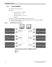
B200 M2 Memory Organization 10 Cisco UCS B200 M2 Blade Server Clock speed: 1333 or 1066 MHz - Registered ■ DDR3 ECC registered DIMMs (RDIMMs), supporting Intel SDDC ■ Memory is organized with three memory channels per CPU, with up to two DIMMs per DIMM: 1, 2, or 4 - CONFIGURING the SERVER STEP 3 CHOOSE MEMORY Figure 3 The standard memory features are: ■ DIMMs - Operational voltage: 1.5 or 1.35 V - Ranks per channel, as shown in Figure 3.
B200 M2 Memory Organization 10 Cisco UCS B200 M2 Blade Server Clock speed: 1333 or 1066 MHz - Registered ■ DDR3 ECC registered DIMMs (RDIMMs), supporting Intel SDDC ■ Memory is organized with three memory channels per CPU, with up to two DIMMs per DIMM: 1, 2, or 4 - CONFIGURING the SERVER STEP 3 CHOOSE MEMORY Figure 3 The standard memory features are: ■ DIMMs - Operational voltage: 1.5 or 1.35 V - Ranks per channel, as shown in Figure 3.

Specifications
Page 12
... in Channels (Channel C is optimized when the DIMM type and quantity are equal for both CPUs. 12 Cisco UCS B200 M2 Blade Server CONFIGURING the SERVER Approved Configurations (1) 1-CPU configuration without memory mirroring: ■ Select from one to six DIMMs per CPU. The DIMMs will be placed by the factory as shown in the following table: Number of DIMMs...
... in Channels (Channel C is optimized when the DIMM type and quantity are equal for both CPUs. 12 Cisco UCS B200 M2 Blade Server CONFIGURING the SERVER Approved Configurations (1) 1-CPU configuration without memory mirroring: ■ Select from one to six DIMMs per CPU. The DIMMs will be placed by the factory as shown in the following table: Number of DIMMs...

Specifications
Page 13
...Serviceability (RAS), mirroring will go unused. If you only have two DIMMs, they need to operate in Performance Mode. ■ Memory mirroring: If you can have two 4-GB and two 8-GB DIMMs. One 4-GB/8-GB DIMM pair would located on Channel A of CPU...In this case, two DIMMS would be located on each of memory channels. NOTE: For memory mirroring, DIMM pairing across buses must be operated in a 1-CPU system, ...in a 2-CPU system, for example, you select the Memory RAS option, be located on three channels). Cisco UCS B200 M2 Blade Server 13 CONFIGURING the SERVER Caveats ■ DIMM ...
...Serviceability (RAS), mirroring will go unused. If you only have two DIMMs, they need to operate in Performance Mode. ■ Memory mirroring: If you can have two 4-GB and two 8-GB DIMMs. One 4-GB/8-GB DIMM pair would located on Channel A of CPU...In this case, two DIMMS would be located on each of memory channels. NOTE: For memory mirroring, DIMM pairing across buses must be operated in a 1-CPU system, ...in a 2-CPU system, for example, you select the Memory RAS option, be located on three channels). Cisco UCS B200 M2 Blade Server 13 CONFIGURING the SERVER Caveats ■ DIMM ...

Specifications
Page 14
...drive types. 14 Cisco UCS B200 M2 Blade Server CONFIGURING the SERVER STEP 4 CHOOSE HARD DISK DRIVES or SOLID STATE DRIVES The standard disk drive features are: ■ 2.5-inch small form factor ■ Hot-pluggable ■ Sled-mounted Choose Drives The available drives are listed in Table 6. Table 6 Available Hot-Pluggable Sled-Mounted SSDs Product... GB 600 GB 900 GB 1 TB SATA 64 GB Approved Configurations (1) Built-In LSI 1064E 4-port SAS 6.0G RAID Mezzanine card RAID controller ■ Select up to two SAS or SATA drives listed in Table 6. Caveats ■ You cannot mix HDD ...
...drive types. 14 Cisco UCS B200 M2 Blade Server CONFIGURING the SERVER STEP 4 CHOOSE HARD DISK DRIVES or SOLID STATE DRIVES The standard disk drive features are: ■ 2.5-inch small form factor ■ Hot-pluggable ■ Sled-mounted Choose Drives The available drives are listed in Table 6. Table 6 Available Hot-Pluggable Sled-Mounted SSDs Product... GB 600 GB 900 GB 1 TB SATA 64 GB Approved Configurations (1) Built-In LSI 1064E 4-port SAS 6.0G RAID Mezzanine card RAID controller ■ Select up to two SAS or SATA drives listed in Table 6. Caveats ■ You cannot mix HDD ...

Specifications
Page 15
.../products/ps10477/prod_technical_reference_list.html Cisco UCS B200 M2 Blade Server 15 CONFIGURING the SERVER STEP 5 CHOOSE A PCIe MEZZANINE CARD The standard PCIe card offerings are: ■ Converged Network Adapters (CNA) ■ Network Interface Cards (NICs) Choose a PCIe Option Card The available PCIe option cards are listed in Table 7. Table 7 Available PCIe Option Cards Product ID (PID) PID Description Converged Network Adapters (CNA) N20...
.../products/ps10477/prod_technical_reference_list.html Cisco UCS B200 M2 Blade Server 15 CONFIGURING the SERVER STEP 5 CHOOSE A PCIe MEZZANINE CARD The standard PCIe card offerings are: ■ Converged Network Adapters (CNA) ■ Network Interface Cards (NICs) Choose a PCIe Option Card The available PCIe option cards are listed in Table 7. Table 7 Available PCIe Option Cards Product ID (PID) PID Description Converged Network Adapters (CNA) N20...
Specifications
Page 17
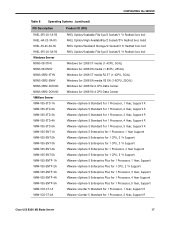
... Support VMware vSphere 5 Enterprise Plus for 1 Processor, 1 Year, Support VMware vSphere 5 Enterprise Plus for 1 CPU, 2 Yr Support VMware vSphere 5 Enterprise Plus for 1 Processor, 3 Year, Support VMware vSphere 5 Enterprise Plus for 1 Processor, 4 Year Support VMware vSphere 5 Enterprise Plus for 1 Processor, 5 Year, Support VMware vCenter 5 Standard for 1 Processor, 1 Year, Support R VMware vCenter 5 Standard for 1 Processor, 2 Year, Support R Cisco UCS B200 M2 Blade Server...
... Support VMware vSphere 5 Enterprise Plus for 1 Processor, 1 Year, Support VMware vSphere 5 Enterprise Plus for 1 CPU, 2 Yr Support VMware vSphere 5 Enterprise Plus for 1 Processor, 3 Year, Support VMware vSphere 5 Enterprise Plus for 1 Processor, 4 Year Support VMware vSphere 5 Enterprise Plus for 1 Processor, 5 Year, Support VMware vCenter 5 Standard for 1 Processor, 1 Year, Support R VMware vCenter 5 Standard for 1 Processor, 2 Year, Support R Cisco UCS B200 M2 Blade Server...
Specifications
Page 21
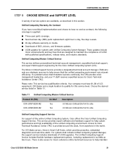
... 24x7x2 On-site Unified Computing Support Service For support of the unified computing environment. Access to Cisco Technical Assistance Center (TAC) is supplied: ■ Three-year parts coverage. ■ Next business day (NBD) parts replacement eight hours a day, five days a week. ■ 90-day software warranty on media. ■ Downloads of BIOS, drivers, and firmware updates. ■ UCSM updates for this section. For systems...
... 24x7x2 On-site Unified Computing Support Service For support of the unified computing environment. Access to Cisco Technical Assistance Center (TAC) is supplied: ■ Three-year parts coverage. ■ Next business day (NBD) parts replacement eight hours a day, five days a week. ■ 90-day software warranty on media. ■ Downloads of BIOS, drivers, and firmware updates. ■ UCSM updates for this section. For systems...
Specifications
Page 23
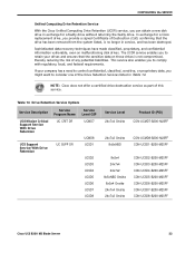
... Drive Retention Services listed in Table 14. In exchange for a faulty drive without returning the faulty drive. NOTE: Cisco does not offer a certified drive destruction service as part of Destruction (CoD) confirming that the sensitive data on malfunctioning disk drives. Table 14 Drive Retention Service Options Service Description Service Program Name Service Level GSP UCS Mission Critical Support Service With Drive Retention UC CRIT DR UCS Support Service With Drive...
... Drive Retention Services listed in Table 14. In exchange for a faulty drive without returning the faulty drive. NOTE: Cisco does not offer a certified drive destruction service as part of Destruction (CoD) confirming that the sensitive data on malfunctioning disk drives. Table 14 Drive Retention Service Options Service Description Service Program Name Service Level GSP UCS Mission Critical Support Service With Drive Retention UC CRIT DR UCS Support Service With Drive...
Specifications
Page 24
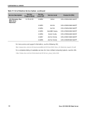
... CON-UCWD7-B200-M2SFF CON-UCWD8-B200-M2SFF For more service and support information, see the following URL: http://www.cisco.com/en/US/services/ps2961/ps10312/ps10321/Cisco_UC_Warranty_Support_DS.pdf For a complete listing of available services for Cisco Unified Computing System, see this URL: http://www.cisco.com/en/US/products/ps10312/serv_group_home.html 24 Cisco UCS B200 M2 Blade Server
... CON-UCWD7-B200-M2SFF CON-UCWD8-B200-M2SFF For more service and support information, see the following URL: http://www.cisco.com/en/US/services/ps2961/ps10312/ps10321/Cisco_UC_Warranty_Support_DS.pdf For a complete listing of available services for Cisco Unified Computing System, see this URL: http://www.cisco.com/en/US/products/ps10312/serv_group_home.html 24 Cisco UCS B200 M2 Blade Server

Specifications
Page 25
... panel) 2 DB-9 serial connector 3 VGA connector (for a monitor) 4 Two-port USB 2.0 connector (for a keyboard and mouse. CONFIGURING the SERVER ORDER OPTIONAL KVM CABLE The KVM cable provides a connection into the server, providing a DB9 serial connector, a VGA connector for a monitor, and dual USB 2.0 ports for a mouse and keyboard) Cisco UCS B200 M2 Blade Server 25 Table 15 KVM Cable Product...
... panel) 2 DB-9 serial connector 3 VGA connector (for a monitor) 4 Two-port USB 2.0 connector (for a keyboard and mouse. CONFIGURING the SERVER ORDER OPTIONAL KVM CABLE The KVM cable provides a connection into the server, providing a DB9 serial connector, a VGA connector for a monitor, and dual USB 2.0 ports for a mouse and keyboard) Cisco UCS B200 M2 Blade Server 25 Table 15 KVM Cable Product...

Specifications
Page 26
... 5 B200 M2 Motherboard 1 Hard drive bays 2 Battery 3 Diagnostic button 4 CPU and heat sink 5 DIMM slots 6 Mezzanine adapter card DIMM and CPU Layout Each CPU controls three memory channels, as follows (refer to Figure 6 on the left are controlled by the CPU on the right (CPU1) and the 6 DIMM slots at the lower left (CPU2). 26 Cisco UCS B200 M2 Blade Server Bank 1 -
... 5 B200 M2 Motherboard 1 Hard drive bays 2 Battery 3 Diagnostic button 4 CPU and heat sink 5 DIMM slots 6 Mezzanine adapter card DIMM and CPU Layout Each CPU controls three memory channels, as follows (refer to Figure 6 on the left are controlled by the CPU on the right (CPU1) and the 6 DIMM slots at the lower left (CPU2). 26 Cisco UCS B200 M2 Blade Server Bank 1 -

Specifications
Page 27
Memory Population Recommendations Table 16 shows the preferred order for installing upgrade DIMMs, and while other configurations may work, if problems arise, moving them to the preferred arrangement should help. Figure 6 DIMM and CPU Layout SUPPLEMENTAL MATERIAL NOTE: The DIMMs at the upper right cannot communicate with the ...CPU CPU 1 Installed Slots 1 A1 2 A1, B1 3 A1, B1, C1 4 A1, A2, B1, C1 5 A1, A2, B1, B2, C1 6 A1, A2, B1, B2, C1, C2 CPU 2 Installed SLots D1 D1, E1 D1, E1, F1 D1, D2, E1, F1 D1, D2, E1, E2, F1 D1, D2, E1, E2, F1, F2 Cisco UCS B200 M2 Blade Server...
Memory Population Recommendations Table 16 shows the preferred order for installing upgrade DIMMs, and while other configurations may work, if problems arise, moving them to the preferred arrangement should help. Figure 6 DIMM and CPU Layout SUPPLEMENTAL MATERIAL NOTE: The DIMMs at the upper right cannot communicate with the ...CPU CPU 1 Installed Slots 1 A1 2 A1, B1 3 A1, B1, C1 4 A1, A2, B1, C1 5 A1, A2, B1, B2, C1 6 A1, A2, B1, B2, C1, C2 CPU 2 Installed SLots D1 D1, E1 D1, E1, F1 D1, D2, E1, F1 D1, D2, E1, E2, F1 D1, D2, E1, E2, F1, F2 Cisco UCS B200 M2 Blade Server...
