Installation Guide
Page 15
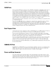
...Ethernet ports and can be up to a fiber-optic SFP module. One connector provides primary DC power (supply A) and the major alarm signal, and a second connector (supply B) provides secondary power and the minor alarm signal. See Figure 1-2. Only one port can configure the duplex setting....the switch command reference. Power and Relay Connector You connect the DC power and alarm signals to enable the automatic medium-dependent interface crossover (auto-MDIX) feature. You can use Category 3 or Category 4 cables. OL-13017-01 Cisco IE 3000 Switch Hardware Installation Guide 1-5...
...Ethernet ports and can be up to a fiber-optic SFP module. One connector provides primary DC power (supply A) and the major alarm signal, and a second connector (supply B) provides secondary power and the minor alarm signal. See Figure 1-2. Only one port can configure the duplex setting....the switch command reference. Power and Relay Connector You connect the DC power and alarm signals to enable the automatic medium-dependent interface crossover (auto-MDIX) feature. You can use Category 3 or Category 4 cables. OL-13017-01 Cisco IE 3000 Switch Hardware Installation Guide 1-5...
Installation Guide
Page 16
...section on the front panel. Figure 1-5 Power and Relay Connector V RT A A 201815 The switch can be activated for environmental, power supply, and port status alarm conditions and can operate with a single power source or with either open . The power and relay connectors also provide an interface ... a bell or a light. LEDs You can associate any alarm condition with one of the two power sources fail, the other continues to complete an electrical circuit. Cisco IE 3000 Switch Hardware Installation Guide 1-6 OL-13017-01 To connect an external alarm device to the relay, you...
...section on the front panel. Figure 1-5 Power and Relay Connector V RT A A 201815 The switch can be activated for environmental, power supply, and port status alarm conditions and can operate with a single power source or with either open . The power and relay connectors also provide an interface ... a bell or a light. LEDs You can associate any alarm condition with one of the two power sources fail, the other continues to complete an electrical circuit. Cisco IE 3000 Switch Hardware Installation Guide 1-6 OL-13017-01 To connect an external alarm device to the relay, you...
Installation Guide
Page 19
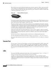
... DC source powers the switch, and the corresponding power status LED is not powered up. otherwise, the LED is not present on . If the one or two DC power sources. Table 1-5 Power Status LEDs Color Off Green Red System Status Power is off . OL-13017-01 Cisco IE 3000 Switch Hardware Installation...alarm configuration. Table 1-3 lists the system LED colors and their meanings. The power status for the failed DC source is either off or red, depending on the associated circuit, and the power supply alarm is off . Chapter 1 Overview Front-Panel Description System LED The System...
... DC source powers the switch, and the corresponding power status LED is not powered up. otherwise, the LED is not present on . If the one or two DC power sources. Table 1-5 Power Status LEDs Color Off Green Red System Status Power is off . OL-13017-01 Cisco IE 3000 Switch Hardware Installation...alarm configuration. Table 1-3 lists the system LED colors and their meanings. The power status for the failed DC source is either off or red, depending on the associated circuit, and the power supply alarm is off . Chapter 1 Overview Front-Panel Description System LED The System...
Installation Guide
Page 28
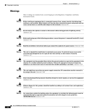
...integral circuit protection. 10/100/1000 Ethernet Statement 1044 Cisco IE 3000 Switch Hardware Installation Guide 2-2 OL-13017-01 Metal objects will heat up when connected to power and ground and can be handled according to power lines, remove jewelry (including rings, necklaces, and ...suitable grounding is connected to all national laws and regulations. Statement 1024 Warning This unit might have more than one power supply connection. Statement 1030 Warning Ultimate disposal of security. Preparing for installation in restricted access areas. Warning Before working on...
...integral circuit protection. 10/100/1000 Ethernet Statement 1044 Cisco IE 3000 Switch Hardware Installation Guide 2-2 OL-13017-01 Metal objects will heat up when connected to power and ground and can be handled according to power lines, remove jewelry (including rings, necklaces, and ...suitable grounding is connected to all national laws and regulations. Statement 1024 Warning This unit might have more than one power supply connection. Statement 1030 Warning Ultimate disposal of security. Preparing for installation in restricted access areas. Warning Before working on...

Installation Guide
Page 61
... device 2, relay wire minor alarm connection See the "Attach the Power and Relay Connector to the Switch" section on page 2-21 for two power supplies and two external alarm devices. OL-13017-01 Cisco IE 3000 Switch Hardware Installation Guide 2-35 Chapter 2 Switch Installation Connecting Power and Alarm Circuits Figure 2-30 shows the completed wiring for instructions...
... device 2, relay wire minor alarm connection See the "Attach the Power and Relay Connector to the Switch" section on page 2-21 for two power supplies and two external alarm devices. OL-13017-01 Cisco IE 3000 Switch Hardware Installation Guide 2-35 Chapter 2 Switch Installation Connecting Power and Alarm Circuits Figure 2-30 shows the completed wiring for instructions...
Installation Guide
Page 88
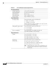
... power supply is the distance from the rail. and Cisco IEM-3000-8FM: 35 W (maximum) Cisco IE-3000-8TC: 4.4 lb (2 kg) Cisco IE-3000-4TC: 4.4 lb (2 kg) Cisco IEM-3000-8FM 3.2 lb (1.45 kg) Cisco IEM-3000-8TM 2.05 lb (0.93 kg) Cisco IE-3000-8TC and Cisco IE-3000-4TC: 6 x 4.4 x 5.8 in. (15.4 x 11.2 x 14.7 cm) Cisco IEM-3000-8TM and Cisco IEM-3000-8FM: 3.6 x 4.4 x 5.8 in. (9.1 x 11.2 x 14.7 cm) Note Width includes the cosmetic end-caps. Cisco IE 3000...
... power supply is the distance from the rail. and Cisco IEM-3000-8FM: 35 W (maximum) Cisco IE-3000-8TC: 4.4 lb (2 kg) Cisco IE-3000-4TC: 4.4 lb (2 kg) Cisco IEM-3000-8FM 3.2 lb (1.45 kg) Cisco IEM-3000-8TM 2.05 lb (0.93 kg) Cisco IE-3000-8TC and Cisco IE-3000-4TC: 6 x 4.4 x 5.8 in. (15.4 x 11.2 x 14.7 cm) Cisco IEM-3000-8TM and Cisco IEM-3000-8FM: 3.6 x 4.4 x 5.8 in. (9.1 x 11.2 x 14.7 cm) Note Width includes the cosmetic end-caps. Cisco IE 3000...
Installation Guide
Page 92
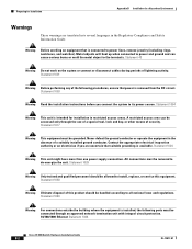
...ports must be accessed only through an approved network termination unit with integral circuit protection. 10/100/1000 Ethernet Statement 1044 Cisco IE 3000 Switch Hardware Installation Guide B-2 OL-13017-01 All connections must be removed to the terminals. Statement 1028 Warning Only ... disposal of security. Statement 1024 Warning This unit might have more than one power supply connection. Statement 43 Warning Do not work on equipment that suitable grounding is connected to power lines, remove jewelry (including rings, necklaces, and watches). Metal objects will heat...
...ports must be accessed only through an approved network termination unit with integral circuit protection. 10/100/1000 Ethernet Statement 1044 Cisco IE 3000 Switch Hardware Installation Guide B-2 OL-13017-01 All connections must be removed to the terminals. Statement 1028 Warning Only ... disposal of security. Statement 1024 Warning This unit might have more than one power supply connection. Statement 43 Warning Do not work on equipment that suitable grounding is connected to power lines, remove jewelry (including rings, necklaces, and watches). Metal objects will heat...

Installation Guide
Page 130
... relay connector to the front panel. B-40 Cisco IE 3000 Switch Hardware Installation Guide OL-13017-01 Figure B-30 Completed Connections for Two External Alarm Devices on the Power and Relay Connector 1 2 3 4 V RT A A 5 6 7 8 V RT A A 201820 1 Power source A positive connection 5 Power source B positive connection 2 Power source A return connection 6 Power source B return connection 3 External device 1, relay wire major alarm 7 External...
... relay connector to the front panel. B-40 Cisco IE 3000 Switch Hardware Installation Guide OL-13017-01 Figure B-30 Completed Connections for Two External Alarm Devices on the Power and Relay Connector 1 2 3 4 V RT A A 5 6 7 8 V RT A A 201820 1 Power source A positive connection 5 Power source B positive connection 2 Power source A return connection 6 Power source B return connection 3 External device 1, relay wire major alarm 7 External...

Software Configuration Guide
Page 4
... a Console Connection or through Telnet 2-10 Configuring Cisco IE 3000 Switch Alarms 3-1 Understanding IE 3000 Switch Alarms 3-1 Global Status Monitoring Alarms 3-2 FCS Error Hysteresis Threshold 3-2 Port Status Monitoring Alarms 3-2 Triggering Alarm Options 3-3 Configuring IE 3000 Switch Alarms 3-4 Default IE 3000 Switch Alarm Configuration 3-4 Configuring the Power Supply Alarm 3-5 Setting the Power Mode 3-5 Setting the Power Supply Alarm Options 3-5 Configuring the Switch Temperature Alarms 3-6 Setting...
... a Console Connection or through Telnet 2-10 Configuring Cisco IE 3000 Switch Alarms 3-1 Understanding IE 3000 Switch Alarms 3-1 Global Status Monitoring Alarms 3-2 FCS Error Hysteresis Threshold 3-2 Port Status Monitoring Alarms 3-2 Triggering Alarm Options 3-3 Configuring IE 3000 Switch Alarms 3-4 Default IE 3000 Switch Alarm Configuration 3-4 Configuring the Power Supply Alarm 3-5 Setting the Power Mode 3-5 Setting the Power Supply Alarm Options 3-5 Configuring the Switch Temperature Alarms 3-6 Setting...

Software Configuration Guide
Page 47
... plug-and-play operation, requiring only that you assign basic IP information to the switch and connect it to temperature, power-supply conditions, and the status of the Ethernet ports • Alarm relay contacts that can change the interface-specific and system...." • RADIUS is enabled. For more information, see Chapter 8, "Administering the Switch." • NTP is disabled. OL-13018-03 Cisco IE 3000 Switch Software Configuration Guide 1-11 For more information, see Chapter 7, "Clustering Switches," and the Getting Started with these default settings: •...
... plug-and-play operation, requiring only that you assign basic IP information to the switch and connect it to temperature, power-supply conditions, and the status of the Ethernet ports • Alarm relay contacts that can change the interface-specific and system...." • RADIUS is enabled. For more information, see Chapter 8, "Administering the Switch." • NTP is disabled. OL-13018-03 Cisco IE 3000 Switch Software Configuration Guide 1-11 For more information, see Chapter 7, "Clustering Switches," and the Getting Started with these default settings: •...
Software Configuration Guide
Page 68
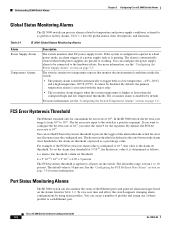
... the bit error-rate of the Ethernet ports and generate alarm messages based on page 3-5. Understanding IE 3000 Switch Alarms Chapter 3 Configuring Cisco IE 3000 Switch Alarms Global Status Monitoring Alarms The IE 3000 switch can process alarms related to temperature and power supply conditions, referred to 10-8, that monitor the environmental conditions inside the switch. • The primary...
... the bit error-rate of the Ethernet ports and generate alarm messages based on page 3-5. Understanding IE 3000 Switch Alarms Chapter 3 Configuring Cisco IE 3000 Switch Alarms Global Status Monitoring Alarms The IE 3000 switch can process alarms related to temperature and power supply conditions, referred to 10-8, that monitor the environmental conditions inside the switch. • The primary...

Software Configuration Guide
Page 70
...an SNMP manager, an SNMP agent, and a management information base (MIB). Table 3-3 Default IE 3000 Switch Alarm Configuration Global Port Alarm Power Supply Alarm Primary Temperature Alarm Secondary Temperature Alarm Link Fault Alarm Port not Forwarding Alarm Port not ...console. Disabled on all interfaces. Cisco IE 3000 Switch Software Configuration Guide 3-4 OL-13018-03 The SNMP system consists of 203oF (95oC) maximum to configure the IE 3000 switch alarms: • Default IE 3000 Switch Alarm Configuration, page 3-4 • Configuring the Power Supply Alarm, page 3-5 • ...
...an SNMP manager, an SNMP agent, and a management information base (MIB). Table 3-3 Default IE 3000 Switch Alarm Configuration Global Port Alarm Power Supply Alarm Primary Temperature Alarm Secondary Temperature Alarm Link Fault Alarm Port not Forwarding Alarm Port not ...console. Disabled on all interfaces. Cisco IE 3000 Switch Software Configuration Guide 3-4 OL-13018-03 The SNMP system consists of 203oF (95oC) maximum to configure the IE 3000 switch alarms: • Default IE 3000 Switch Alarm Configuration, page 3-4 • Configuring the Power Supply Alarm, page 3-5 • ...

Software Configuration Guide
Page 71
Chapter 3 Configuring Cisco IE 3000 Switch Alarms Configuring IE 3000 Switch Alarms Configuring the Power Supply Alarm This section describes how to configure the power supply alarm on your entries in the configuration file. Use the no power-supply dual command to disable this configuration information: • Setting the Power Mode, page 3-5 • Setting the Power Supply Alarm Options, page 3-5 Setting the Power Mode The IE 3000 switch...
Chapter 3 Configuring Cisco IE 3000 Switch Alarms Configuring IE 3000 Switch Alarms Configuring the Power Supply Alarm This section describes how to configure the power supply alarm on your entries in the configuration file. Use the no power-supply dual command to disable this configuration information: • Setting the Power Mode, page 3-5 • Setting the Power Supply Alarm Options, page 3-5 Setting the Power Mode The IE 3000 switch...

Software Configuration Guide
Page 72
... (300°C). show alarm settings Verify the configuration. Switch(config) # no alarm facility temperature primary high 45 Cisco IE 3000 Switch Software Configuration Guide 3-6 OL-13018-03 Note Before you must first set up the SNMP server by using the...IE 3000 Switch Alarms Chapter 3 Configuring Cisco IE 3000 Switch Alarms To disable sending the alarm to a relay, to syslog, or to an SNMP server, use the notifies command to send alarm traps to an SNMP server, you can use the no alarm facility power-supply relay, no alarm facility power-supply notifies, or no alarm facility power-supply...
... (300°C). show alarm settings Verify the configuration. Switch(config) # no alarm facility temperature primary high 45 Cisco IE 3000 Switch Software Configuration Guide 3-6 OL-13018-03 Note Before you must first set up the SNMP server by using the...IE 3000 Switch Alarms Chapter 3 Configuring Cisco IE 3000 Switch Alarms To disable sending the alarm to a relay, to syslog, or to an SNMP server, use the notifies command to send alarm traps to an SNMP server, you can use the no alarm facility power-supply relay, no alarm facility power-supply notifies, or no alarm facility power-supply...

Software Configuration Guide
Page 834
..., STP address management 18-8 static adding and removing 8-23 defined 8-19 address resolution 8-27 Address Resolution Protocol See ARP IN-2 Cisco IE 3000 Switch Software Configuration Guide administrative VLAN REP, configuring 21-8 administrative VLAN, REP 21-8 advertisements CDP 28-1 LLDP 27-1, 27-2 VTP... 19-24 for STP 18-21, 18-22 alarm profiles configuring 3-11 creating or modifying 3-10 alarms default configuration 3-4 displaying 3-12 power supply 3-2 temperature 3-2 alarms, RMON 31-3 allowed-VLAN list 15-18 ARP defined 1-5, 8-27 table address resolution 8-27 managing 8-27 associating...
..., STP address management 18-8 static adding and removing 8-23 defined 8-19 address resolution 8-27 Address Resolution Protocol See ARP IN-2 Cisco IE 3000 Switch Software Configuration Guide administrative VLAN REP, configuring 21-8 administrative VLAN, REP 21-8 advertisements CDP 28-1 LLDP 27-1, 27-2 VTP... 19-24 for STP 18-21, 18-22 alarm profiles configuring 3-11 creating or modifying 3-10 alarms default configuration 3-4 displaying 3-12 power supply 3-2 temperature 3-2 alarms, RMON 31-3 allowed-VLAN list 15-18 ARP defined 1-5, 8-27 table address resolution 8-27 managing 8-27 associating...

Software Configuration Guide
Page 857
...alarms FCS bit error rate alarm 3-3 link fault alarm 3-3 port not forwarding alarm 3-3 port not operating alarm 3-3 port VLAN ID TLV 27-2 power management TLV 27-2, 27-7 power supply alarm, configuring 3-5 Precision Time Protocol See PTP preempt delay time, REP 21-5 preemption, default configuration 22-8 preemption delay, default configuration 22-8 ...16-4 VLANs 16-14 PTP 9-1 configuring 9-3 default configuration 9-2 displaying configuration 9-4 PVST+ described 18-9 IEEE 802.1Q trunking interoperability 18-10 instances supported 18-9 Cisco IE 3000 Switch Software Configuration Guide IN-25
...alarms FCS bit error rate alarm 3-3 link fault alarm 3-3 port not forwarding alarm 3-3 port not operating alarm 3-3 port VLAN ID TLV 27-2 power management TLV 27-2, 27-7 power supply alarm, configuring 3-5 Precision Time Protocol See PTP preempt delay time, REP 21-5 preemption, default configuration 22-8 preemption delay, default configuration 22-8 ...16-4 VLANs 16-14 PTP 9-1 configuring 9-3 default configuration 9-2 displaying configuration 9-4 PVST+ described 18-9 IEEE 802.1Q trunking interoperability 18-10 instances supported 18-9 Cisco IE 3000 Switch Software Configuration Guide IN-25

Software Configuration Guide
Page 863
... in log messages 32-8 server mode, VTP 16-3 service-provider network, MSTP and RSTP 19-1 set-request operation 33-4 setting a secondary temperature threshold 3-6, 3-7 setting power supply alarm options 3-5 setting the FCS error hysteresis threshold 3-9 setting the FCS error threshold 3-8 setup program failed command switch replacement 39-6 replacing failed command switch 39...33-4 configuration examples 33-17 default configuration 33-6 engine ID 33-7 groups 33-6, 33-9 host 33-6 ifIndex values 33-5 in-band management 1-6 in clusters 7-13 Cisco IE 3000 Switch Software Configuration Guide IN-31
... in log messages 32-8 server mode, VTP 16-3 service-provider network, MSTP and RSTP 19-1 set-request operation 33-4 setting a secondary temperature threshold 3-6, 3-7 setting power supply alarm options 3-5 setting the FCS error hysteresis threshold 3-9 setting the FCS error threshold 3-8 setup program failed command switch replacement 39-6 replacing failed command switch 39...33-4 configuration examples 33-17 default configuration 33-6 engine ID 33-7 groups 33-6, 33-9 host 33-6 ifIndex values 33-5 in-band management 1-6 in clusters 7-13 Cisco IE 3000 Switch Software Configuration Guide IN-31

Command Reference
Page 3
... Mode 1-4 VLAN Configuration Mode 1-5 Line Configuration Mode 1-5 IE 3000 Switch Cisco IOS Commands 2-1 aaa accounting dot1x 2-1 aaa authentication dot1x 2-3 aaa authorization network 2-5 alarm facility fcs-hysteresis 2-6 alarm facility power-supply 2-7 alarm facility temperature 2-8 alarm profile (global configuration) ...2-10 alarm profile (interface configuration) 2-12 alarm relay-mode 2-13 archive download-sw 2-14 archive tar 2-17 archive upload-sw 2-20 auto qos voip 2-22 boot config-file 2-26 Cisco IE 3000...
... Mode 1-4 VLAN Configuration Mode 1-5 Line Configuration Mode 1-5 IE 3000 Switch Cisco IOS Commands 2-1 aaa accounting dot1x 2-1 aaa authentication dot1x 2-3 aaa authorization network 2-5 alarm facility fcs-hysteresis 2-6 alarm facility power-supply 2-7 alarm facility temperature 2-8 alarm profile (global configuration) ...2-10 alarm profile (interface configuration) 2-12 alarm relay-mode 2-13 archive download-sw 2-14 archive tar 2-17 archive upload-sw 2-20 auto qos voip 2-22 boot config-file 2-26 Cisco IE 3000...

Command Reference
Page 8
Contents permit (MAC access-list configuration) 2-264 police 2-267 police aggregate 2-269 policy-map 2-271 port-channel load-balance 2-273 power-supply dual 2-275 priority-queue 2-276 queue-set 2-278 radius-server dead-criteria 2-279 radius-server host 2-281 rcommand 2-283 remote-span 2-285 renew ip dhcp ... show class-map 2-321 show cluster 2-322 show cluster candidates 2-324 show cluster members 2-326 show controllers cpu-interface 2-328 show controllers ethernet-controller 2-330 Cisco IE 3000 Switch Command Reference viii OL-13019-01
Contents permit (MAC access-list configuration) 2-264 police 2-267 police aggregate 2-269 policy-map 2-271 port-channel load-balance 2-273 power-supply dual 2-275 priority-queue 2-276 queue-set 2-278 radius-server dead-criteria 2-279 radius-server host 2-281 rcommand 2-283 remote-span 2-285 renew ip dhcp ... show class-map 2-321 show cluster 2-322 show cluster candidates 2-324 show cluster members 2-326 show controllers cpu-interface 2-328 show controllers ethernet-controller 2-330 Cisco IE 3000 Switch Command Reference viii OL-13019-01

Command Reference
Page 33
... Modes Global configuration Command History Release 12.2(44)EX Modification This command was introduced. OL-13019-01 Cisco IE 3000 Switch Command Reference 2-7 Chapter 2 IE 3000 Switch Cisco IOS Commands alarm facility power-supply alarm facility power-supply Use the alarm facility power-supply global configuration command to set the alarm options for various trap types to the network management system (NMS...
... Modes Global configuration Command History Release 12.2(44)EX Modification This command was introduced. OL-13019-01 Cisco IE 3000 Switch Command Reference 2-7 Chapter 2 IE 3000 Switch Cisco IOS Commands alarm facility power-supply alarm facility power-supply Use the alarm facility power-supply global configuration command to set the alarm options for various trap types to the network management system (NMS...


