Installation Guide
Page 15
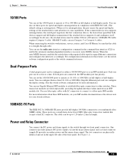
...) Ethernet ports and can configure the duplex setting. (See the switch software configuration for more information about these ports for speed and duplex autonegotiation in an SFP module slot. For more information.) You can configure them as an SFP module port. OL-13017-01 Cisco IE 3000 Switch Hardware... Installation Guide 1-5 You can use a small-form-factor fixed (SFF) fiber-optic transceiver module that the cable is , the fastest line speed that both ports are field-replaceable, providing the uplink interfaces when ...
...) Ethernet ports and can configure the duplex setting. (See the switch software configuration for more information about these ports for speed and duplex autonegotiation in an SFP module slot. For more information.) You can configure them as an SFP module port. OL-13017-01 Cisco IE 3000 Switch Hardware... Installation Guide 1-5 You can use a small-form-factor fixed (SFF) fiber-optic transceiver module that the cable is , the fastest line speed that both ports are field-replaceable, providing the uplink interfaces when ...

Installation Guide
Page 17
Chapter 1 Overview Figure 1-6 1 2 3 4 LEDs on the Cisco IE 3000 Switch Front-Panel Description 201703 5 67 8 1 Express setup button 2 System LED 3 Alarm LED 4 Setup LED 5 Dual-purpose uplink port LED 6 Pwr B LED 7 Pwr A LED 8 Port LED Figure 1-7 LEDs on the Cisco IEM-3000-8TM Module 201706 1 1 10/100 port LED OL-13017-01 Cisco IE 3000 Switch Hardware Installation Guide 1-7
Chapter 1 Overview Figure 1-6 1 2 3 4 LEDs on the Cisco IE 3000 Switch Front-Panel Description 201703 5 67 8 1 Express setup button 2 System LED 3 Alarm LED 4 Setup LED 5 Dual-purpose uplink port LED 6 Pwr B LED 7 Pwr A LED 8 Port LED Figure 1-7 LEDs on the Cisco IEM-3000-8TM Module 201706 1 1 10/100 port LED OL-13017-01 Cisco IE 3000 Switch Hardware Installation Guide 1-7
Installation Guide
Page 20
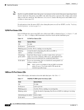
... Note After a port is present. Link is reconfigured, the port LED can affect connectivity, and errors such as shown in Figure 1-6, Figure 1-7, and Figure 1-8. Solid green Link present. Alternating green-amber Link fault. Activity. Link is disabled. 1-10 Cisco IE 3000 Switch Hardware Installation Guide ... about the switch and the individual ports. Front-Panel Description Chapter 1 Overview Note The Pwr A and Pwr B LEDs show that power is sending or receiving data. See Table 1-7. Port is sending or receiving data. Table 1-7 100BASE-FX MM Uplink Port Status LEDs ...
... Note After a port is present. Link is reconfigured, the port LED can affect connectivity, and errors such as shown in Figure 1-6, Figure 1-7, and Figure 1-8. Solid green Link present. Alternating green-amber Link fault. Activity. Link is disabled. 1-10 Cisco IE 3000 Switch Hardware Installation Guide ... about the switch and the individual ports. Front-Panel Description Chapter 1 Overview Note The Pwr A and Pwr B LEDs show that power is sending or receiving data. See Table 1-7. Port is sending or receiving data. Table 1-7 100BASE-FX MM Uplink Port Status LEDs ...

Installation Guide
Page 63
... the port LED turns green. OL-13017-01 Cisco IE 3000 Switch Hardware Installation Guide 2-37 These field-replaceable modules provide the uplink optical interfaces, send (TX) and receive (RX). See the Cisco IE 3000 release ...notes for SFP module connections. Repeat Steps 1 through 3 to install and remove SFP modules. The port LED turns on the front of the switch. This can use any combination of rugged SFP modules. See Table C-1 on the other device. Chapter 2 Switch Installation Figure 2-31 Connecting to an Ethernet Port Connecting Destination Ports...
... the port LED turns green. OL-13017-01 Cisco IE 3000 Switch Hardware Installation Guide 2-37 These field-replaceable modules provide the uplink optical interfaces, send (TX) and receive (RX). See the Cisco IE 3000 release ...notes for SFP module connections. Repeat Steps 1 through 3 to install and remove SFP modules. The port LED turns on the front of the switch. This can use any combination of rugged SFP modules. See Table C-1 on the other device. Chapter 2 Switch Installation Figure 2-31 Connecting to an Ethernet Port Connecting Destination Ports...

Installation Guide
Page 132
... connections. B-42 Cisco IE 3000 Switch Hardware Installation Guide OL-13017-01 These field-replaceable modules provide the uplink optical interfaces, send (TX) and receive (RX). Installing and Removing SFP Modules These sections describe how to 30 seconds, and then the port LED turns green.... the topology and searches for the list of supported modules. Connecting Destination Ports Appendix B Installation In a Hazardous Environment Figure B-31 Connecting to an Ethernet Port 201881 1 2 1 10/100/1000 port 2 10/100 ports Step 2 Step 3 Step 4 Connect the other end of the cable...
... connections. B-42 Cisco IE 3000 Switch Hardware Installation Guide OL-13017-01 These field-replaceable modules provide the uplink optical interfaces, send (TX) and receive (RX). Installing and Removing SFP Modules These sections describe how to 30 seconds, and then the port LED turns green.... the topology and searches for the list of supported modules. Connecting Destination Ports Appendix B Installation In a Hazardous Environment Figure B-31 Connecting to an Ethernet Port 201881 1 2 1 10/100/1000 port 2 10/100 ports Step 2 Step 3 Step 4 Connect the other end of the cable...

Installation Guide
Page 153
... fiber-optic uplink ports (see Figure C-3) and for a list of supported SFP modules. or 62.5/125-micron multimode fiber-optic cabling. See the switch release notes for copper SFP ports (see Figure C-4). See Figure C-3. Figure C-4 Pin 1 2 3 4 5 6 7 8 Copper SFP Module RJ-45 Connector Label 12345678 TP0+ TP0TP1+ TP2+ TP2TP1TP3+ TP3- 60915 OL-13017-01 Cisco IE 3000 Switch Hardware...
... fiber-optic uplink ports (see Figure C-3) and for a list of supported SFP modules. or 62.5/125-micron multimode fiber-optic cabling. See the switch release notes for copper SFP ports (see Figure C-4). See Figure C-3. Figure C-4 Pin 1 2 3 4 5 6 7 8 Copper SFP Module RJ-45 Connector Label 12345678 TP0+ TP0TP1+ TP2+ TP2TP1TP3+ TP3- 60915 OL-13017-01 Cisco IE 3000 Switch Hardware...

Installation Guide
Page 154
...the required cable length. The auto-MDIX feature is used with Cisco IE 3000 switches. • SFP Module Cable Specifications, page C-4 • Two Twisted-Pair Cable Pinouts, page C-5 • Four Twisted-Pair Cable Pinouts for 1000BASE-T Ports, page C-6 • Crossover Cable and Adapter Pinouts, page C-7... C-2 and Table C-3. You can order a kit (part number ACS-DSBUASYN=) containing that adapter from Cisco. Cable and Adapter Specifications Appendix C Cable and Connectors Dual-Purpose Ports The Ethernet port on the other end of the cable, and for fiber-optic and copper uplink ports.
...the required cable length. The auto-MDIX feature is used with Cisco IE 3000 switches. • SFP Module Cable Specifications, page C-4 • Two Twisted-Pair Cable Pinouts, page C-5 • Four Twisted-Pair Cable Pinouts for 1000BASE-T Ports, page C-6 • Crossover Cable and Adapter Pinouts, page C-7... C-2 and Table C-3. You can order a kit (part number ACS-DSBUASYN=) containing that adapter from Cisco. Cable and Adapter Specifications Appendix C Cable and Connectors Dual-Purpose Ports The Ethernet port on the other end of the cable, and for fiber-optic and copper uplink ports.


