
User Guide
Page 12
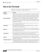
... connector specifications. It includes a description of the switch. How to Use This Guide Welcome How to Use This Guide This guide covers the topics to help you learn more about the switch and how to effectively use to monitor the status and the performance of the device manager user interface, the switch hardware and software requirements, and the supported related products. Use this way: Chapters Introduction Setup and Installation Customization Monitoring Troubleshooting Reference Cisco Support...
... connector specifications. It includes a description of the switch. How to Use This Guide Welcome How to Use This Guide This guide covers the topics to help you learn more about the switch and how to effectively use to monitor the status and the performance of the device manager user interface, the switch hardware and software requirements, and the supported related products. Use this way: Chapters Introduction Setup and Installation Customization Monitoring Troubleshooting Reference Cisco Support...

User Guide
Page 18
... both power and network access to PoE-capable devices, such as IP phones and access points. Features and Benefits • Hardware Features, page 1-5 • Software Features, page 1-7 • Device Manager GUI, page 1-8 User Guide for the Catalyst Express 500 Switches 1-4 OL-8122-01 Features and Benefits Chapter 1 Introduction PoE connections from their connections to the switch. PoE devices can receive up to optimize the connections in the Catalyst Express switches), through Cisco Network Assistant, or through Smartports Port...
... both power and network access to PoE-capable devices, such as IP phones and access points. Features and Benefits • Hardware Features, page 1-5 • Software Features, page 1-7 • Device Manager GUI, page 1-8 User Guide for the Catalyst Express 500 Switches 1-4 OL-8122-01 Features and Benefits Chapter 1 Introduction PoE connections from their connections to the switch. PoE devices can receive up to optimize the connections in the Catalyst Express switches), through Cisco Network Assistant, or through Smartports Port...
User Guide
Page 19
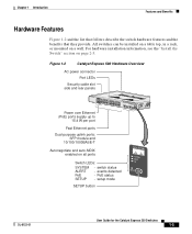
...-01 User Guide for the Catalyst Express 500 Switches 1-5 Figure 1-2 Catalyst Express 500 Hardware Overview AC power connector Port LEDs Security cable slot side and rear panels 12 1X 34 56 2X POWER OVER ETHERNET 78 9 10 11 12 11X 13X 13 14 12X 14X 15 16 17 18 19 20 21 22 23 24 23X 24X Power over Ethernet (PoE) ports supply up to 15.4 W per port Catalyst Express 500 SERIES...
...-01 User Guide for the Catalyst Express 500 Switches 1-5 Figure 1-2 Catalyst Express 500 Hardware Overview AC power connector Port LEDs Security cable slot side and rear panels 12 1X 34 56 2X POWER OVER ETHERNET 78 9 10 11 12 11X 13X 13 14 12X 14X 15 16 17 18 19 20 21 22 23 24 23X 24X Power over Ethernet (PoE) ports supply up to 15.4 W per port Catalyst Express 500 SERIES...

User Guide
Page 20
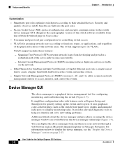
...-compliant powered devices if the switch detects that there is in the "Supported Hardware" section on page 1-13. User Guide for switch connectivity. A list of an installed Cisco redundant power supply (RPS). (Available only on the Catalyst Express 500-24PC model.) Setup Button • Button starts the Express Setup program. SFP Module Slots • Fiber-optic SFP modules provide cable media and distance options for the Catalyst Express 500 Switches 1-6 OL-8122-01 Cisco Redundant Power Supply (RPS) • Cisco redundant power supply (RPS) enhances power...
...-compliant powered devices if the switch detects that there is in the "Supported Hardware" section on page 1-13. User Guide for switch connectivity. A list of an installed Cisco redundant power supply (RPS). (Available only on the Catalyst Express 500-24PC model.) Setup Button • Button starts the Express Setup program. SFP Module Slots • Fiber-optic SFP modules provide cable media and distance options for the Catalyst Express 500 Switches 1-6 OL-8122-01 Cisco Redundant Power Supply (RPS) • Cisco redundant power supply (RPS) enhances power...
User Guide
Page 21
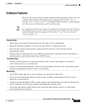
... error percentages, and temperature and fan status. • Port status and statistics tables display port operating status and the statistics for first-time switch configuration. • Quick IP information updates if you relocate the switch to a different network. • Date and time settings automatically synchronized between the switch and the network management station. • Dynamic Host Configuration Protocol (DHCP) automatically assigns the switch an IP address, a default gateway, and a subnet mask from a DHCP server. OL-8122-01 User Guide for the Catalyst...
... error percentages, and temperature and fan status. • Port status and statistics tables display port operating status and the statistics for first-time switch configuration. • Quick IP information updates if you relocate the switch to a different network. • Date and time settings automatically synchronized between the switch and the network management station. • Dynamic Host Configuration Protocol (DHCP) automatically assigns the switch an IP address, a default gateway, and a subnet mask from a DHCP server. OL-8122-01 User Guide for the Catalyst...
User Guide
Page 22
... the physical location of service (QoS) benefits are available from the software download page on using the device manager windows are built into a single logical link to create a higher bandwidth link between the switch and another switch. • Simple Network Management Protocol (SNMP) versions 1, 2C, and 3 to allow a remote network management station to 32 VLANs. It uses graphical, color-coded displays such as Express Setup and Smartports for configuring, monitoring, and troubleshooting the switch (Figure 1-3). Security and quality of the network users.
... the physical location of service (QoS) benefits are available from the software download page on using the device manager windows are built into a single logical link to create a higher bandwidth link between the switch and another switch. • Simple Network Management Protocol (SNMP) versions 1, 2C, and 3 to allow a remote network management station to 32 VLANs. It uses graphical, color-coded displays such as Express Setup and Smartports for configuring, monitoring, and troubleshooting the switch (Figure 1-3). Security and quality of the network users.

User Guide
Page 30
... "VLAN Types" section on the switch. The default ID is default. If they are in different VLANs, a router or Layer 3 switch is limited to take advantage of your network management station are the configuration settings that should only be managed, and switch monitoring is needed to all devices in the Getting Started Guide for the Catalyst Express 500 Switches 2-2 OL-8122-01 It also ensures secure, administrative access to communicate between specific users or devices.
... "VLAN Types" section on the switch. The default ID is default. If they are in different VLANs, a router or Layer 3 switch is limited to take advantage of your network management station are the configuration settings that should only be managed, and switch monitoring is needed to all devices in the Getting Started Guide for the Catalyst Express 500 Switches 2-2 OL-8122-01 It also ensures secure, administrative access to communicate between specific users or devices.
User Guide
Page 32
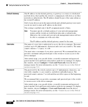
... the device manager menu. The password cannot contain a ? To display this window, choose Configure > Users and Passwords from the device manager menu. The IP address should be part of a user who is not used, you enter a password. We recommend that you can have up to the device manager. The name cannot contain a ?, a space, or a tab. Set Up the Switch for the First Time Chapter 2 Setup and Installation Default Gateway Username Password The IP address for the Catalyst...
... the device manager menu. The password cannot contain a ? To display this window, choose Configure > Users and Passwords from the device manager menu. The IP address should be part of a user who is not used, you enter a password. We recommend that you can have up to the device manager. The name cannot contain a ?, a space, or a tab. Set Up the Switch for the First Time Chapter 2 Setup and Installation Default Gateway Username Password The IP address for the Catalyst...

User Guide
Page 44
... Smartports window on the type of devices to be connected to traffic from the switches is optimized for its attached device. It shows port roles applied to it. The Smartports port roles are Cisco-recommended configurations for the Catalyst Express 500 Switches 3-2 OL-8122-01 The port roles (Table 3-1) are based on the device manager. For example, the Desktop port role is an example of devices connected to the switch ports. User Guide for the switch ports. Only port...
... Smartports window on the type of devices to be connected to traffic from the switches is optimized for its attached device. It shows port roles applied to it. The Smartports port roles are Cisco-recommended configurations for the Catalyst Express 500 Switches 3-2 OL-8122-01 The port roles (Table 3-1) are based on the device manager. For example, the Desktop port role is an example of devices connected to the switch ports. User Guide for the switch ports. Only port...

User Guide
Page 48
... switch port will be connected to the switch ports. User Guide for additional guidelines and procedures. Note • We recommend that are connected to routers or to the network • Reduce protection from the device manager menu. For example, mismatches • Affect the behavior of the attached device • Lower network performance (reduce the level of QoS) on voice, wireless, switch, and router traffic • Reduce restrictions on guest access to other switches...
... switch port will be connected to the switch ports. User Guide for additional guidelines and procedures. Note • We recommend that are connected to routers or to the network • Reduce protection from the device manager menu. For example, mismatches • Affect the behavior of the attached device • Lower network performance (reduce the level of QoS) on voice, wireless, switch, and router traffic • Reduce restrictions on guest access to other switches...
User Guide
Page 51
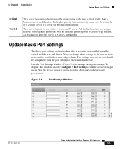
... business-type servers. Figure 3-4 Port Settings Window OL-8122-01 User Guide for additional guidelines and procedures. This server type is Cisco CallManager. You can change these settings to fit your network needs and to change basic port settings. Update Basic Port Settings The basic port settings determine how data is a server for use with a voice-over-IP server. All traffic from this window, choose Configure > Port Settings from the device manager menu. An example of a critical server is received and sent between the switch...
... business-type servers. Figure 3-4 Port Settings Window OL-8122-01 User Guide for additional guidelines and procedures. This server type is Cisco CallManager. You can change these settings to fit your network needs and to change basic port settings. Update Basic Port Settings The basic port settings determine how data is a server for use with a voice-over-IP server. All traffic from this window, choose Configure > Port Settings from the device manager menu. An example of a critical server is received and sent between the switch...

User Guide
Page 52
... the required cable connection type (straight-through or crossover) and configure the connection appropriately. Note To reenable auto-MDIX, first set to Auto. 3-10 User Guide for the switch ports: Description Enable Speed Duplex The description of the switch port. The limit is Auto. Disable the port to help identify the port during monitoring and troubleshooting. The operating speed of the switch port. The default is 18 characters. The default is Enable. We recommend using the default so that...
... the required cable connection type (straight-through or crossover) and configure the connection appropriately. Note To reenable auto-MDIX, first set to Auto. 3-10 User Guide for the switch ports: Description Enable Speed Duplex The description of the switch port. The limit is Auto. Disable the port to help identify the port during monitoring and troubleshooting. The operating speed of the switch port. The default is 18 characters. The default is Enable. We recommend using the default so that...
User Guide
Page 53
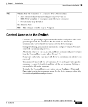
... the switch has at least one username-and-password pair to secure access to the Switch Username-and-password pairs prevent unauthorized access by those who could guess the password. Chapter 3 Customization Control Access to the Switch PoE Whether PoE will be supplied to automatically provide power when an IEEE 802.af-compliant or Cisco pre-standard device is available only on PoE ports. Choose either: • Auto (automatically) to a connected device. The default is Auto.
... the switch has at least one username-and-password pair to secure access to the Switch Username-and-password pairs prevent unauthorized access by those who could guess the password. Chapter 3 Customization Control Access to the Switch PoE Whether PoE will be supplied to automatically provide power when an IEEE 802.af-compliant or Cisco pre-standard device is available only on PoE ports. Choose either: • Auto (automatically) to a connected device. The default is Auto.
User Guide
Page 79
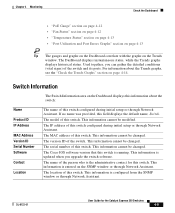
... User Guide for this switch configured during initial setup or through Network Assistant. For information about the switch: Name Product ID IP Address MAC Address Version ID Serial Number Software Contact Location The name of this switch. This information is running. This information is configured from the SNMP window or through Network Assistant. If no name was provided, this switch. This information cannot be changed . The serial number of this switch. The model of this switch...
... User Guide for this switch configured during initial setup or through Network Assistant. For information about the switch: Name Product ID IP Address MAC Address Version ID Serial Number Software Contact Location The name of this switch. This information is running. This information is configured from the SNMP window or through Network Assistant. If no name was provided, this switch. This information cannot be changed . The serial number of this switch. The model of this switch...

User Guide
Page 98
... the network. From the Restart / Reset window, you to eliminate probable causes. To display this window, choose Configure > Restart / Reset from the device manager menu. However, the device manager is causing the problem. Use the Restart / Reset window to its saved configuration settings during the process. You can : • Restart the switch without turning off power. User Guide for additional guidelines and procedures. Restart or Reset the Switch Figure 5-2 Sample Diagnostics Report Chapter 5 Troubleshooting...
... the network. From the Restart / Reset window, you to eliminate probable causes. To display this window, choose Configure > Restart / Reset from the device manager menu. However, the device manager is causing the problem. Use the Restart / Reset window to its saved configuration settings during the process. You can : • Restart the switch without turning off power. User Guide for additional guidelines and procedures. Restart or Reset the Switch Figure 5-2 Sample Diagnostics Report Chapter 5 Troubleshooting...

User Guide
Page 101
... User Guide for the Catalyst Express 500 Switches 5-7 However, the device manager cannot automatically redisplay after a few seconds), follow the procedures in the Getting Started Guide for example, an Upgrade Failed message appears or the System LED does not turn solid green after the software upgrade completes if the switch was previously running the cryptographic version and if the device manager was accessed through a secured session. Make sure that there is connectivity between the switch...
... User Guide for the Catalyst Express 500 Switches 5-7 However, the device manager cannot automatically redisplay after a few seconds), follow the procedures in the Getting Started Guide for example, an Upgrade Failed message appears or the System LED does not turn solid green after the software upgrade completes if the switch was previously running the cryptographic version and if the device manager was accessed through a secured session. Make sure that there is connectivity between the switch...
User Guide
Page 102
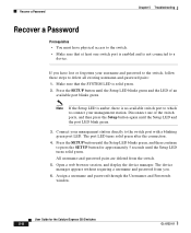
... port LED blink green. 3. Connect your management station directly to the switch port with a blinking green port LED. Note If the Setup LED is amber, there is solid green. 2. Press the SETUP button until the Setup LED turns solid green. User Guide for approximately 5 seconds until the Setup LED blinks green, and then continue to press the SETUP button for the Catalyst Express 500 Switches 5-8 OL-8122-01 Assign a username and password through the Usernames and Passwords window. If you . 6. Disconnect one switch port is enabled and is not connected to a device...
... port LED blink green. 3. Connect your management station directly to the switch port with a blinking green port LED. Note If the Setup LED is amber, there is solid green. 2. Press the SETUP button until the Setup LED turns solid green. User Guide for approximately 5 seconds until the Setup LED blinks green, and then continue to press the SETUP button for the Catalyst Express 500 Switches 5-8 OL-8122-01 Assign a username and password through the Usernames and Passwords window. If you . 6. Disconnect one switch port is enabled and is not connected to a device...
User Guide
Page 104
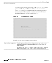
... you must set up the switch again, as described in the Getting Started Guide for the Catalyst Express 500 Switches. 5-10 User Guide for the Catalyst Express 500 Switches OL-8122-01 Connect your management station directly to delete all the configuration settings on the switch, including the IP address, usernames, and passwords, but retain the software image. Open a web browser session, and display the device manager. The port LED turns solid green after the connection. 5. Recover the Switch Software Chapter 5 Troubleshooting 4.
... you must set up the switch again, as described in the Getting Started Guide for the Catalyst Express 500 Switches. 5-10 User Guide for the Catalyst Express 500 Switches OL-8122-01 Connect your management station directly to delete all the configuration settings on the switch, including the IP address, usernames, and passwords, but retain the software image. Open a web browser session, and display the device manager. The port LED turns solid green after the connection. 5. Recover the Switch Software Chapter 5 Troubleshooting 4.
User Guide
Page 105
... Done Use the diagnostic tools and troubleshooting features to solve network problems as they come up the switch again, as described in the Getting Started Guide for the Catalyst Express 500 Switches. Display the device manager, and try to upgrade the switch software again. Settings for the Catalyst Express 500 Switches 5-11 If you troubleshoot problems, see Chapter , "Cisco Support Resources." Chapter 5 Troubleshooting When You Are Done Boot with the factory and to change to the factory-default software...
... Done Use the diagnostic tools and troubleshooting features to solve network problems as they come up the switch again, as described in the Getting Started Guide for the Catalyst Express 500 Switches. Display the device manager, and try to upgrade the switch software again. Settings for the Catalyst Express 500 Switches 5-11 If you troubleshoot problems, see Chapter , "Cisco Support Resources." Chapter 5 Troubleshooting When You Are Done Boot with the factory and to change to the factory-default software...

User Guide
Page 133
... hardware 1-11 software 1-11 reset switch 5-4 Restart / Reset window displaying 5-4 using 5-4 restart switch 5-4 restore settings 5-5 RPS features 1-6 supported 1-13 S safety warnings 2-6 secured sessions See SSL Secure Socket Layer See SSL security reporting problems B-6 vulnerability policy B-5 security slots, features 1-6 server priorities changing 3-8 default 3-8 description of 3-8 Setup button 4-3 features 1-6 password recovery 5-8 software recovery 5-9 SFP module ports LC connector A-17 LC patch cables A-15 SFP modules features 1-6 supported 1-13 OL-8122-01 User Guide for the Catalyst...
... hardware 1-11 software 1-11 reset switch 5-4 Restart / Reset window displaying 5-4 using 5-4 restart switch 5-4 restore settings 5-5 RPS features 1-6 supported 1-13 S safety warnings 2-6 secured sessions See SSL Secure Socket Layer See SSL security reporting problems B-6 vulnerability policy B-5 security slots, features 1-6 server priorities changing 3-8 default 3-8 description of 3-8 Setup button 4-3 features 1-6 password recovery 5-8 software recovery 5-9 SFP module ports LC connector A-17 LC patch cables A-15 SFP modules features 1-6 supported 1-13 OL-8122-01 User Guide for the Catalyst...


