Hardware Installation Guide
Page 4
... 2-11 Safety 2-11 Preventing Electrostatic Discharge Damage 2-12 Electrical Safety 2-13 Receiving the Cisco 10000 Series Router 2-14 Chassis-Lifting Guidelines 2-15 Required Tools and Equipment 2-16 Verifying Contents After Unpacking 2-16 3 C H A P T E R Installing the Cisco 10008 Router 3-1 Installation Methods 3-1 Rack-Mounting the Chassis 3-2 General Rack Installation Guidelines 3-2 Flush-Mounting in a 19-Inch Rack 3-3 Center-Mounting...
... 2-11 Safety 2-11 Preventing Electrostatic Discharge Damage 2-12 Electrical Safety 2-13 Receiving the Cisco 10000 Series Router 2-14 Chassis-Lifting Guidelines 2-15 Required Tools and Equipment 2-16 Verifying Contents After Unpacking 2-16 3 C H A P T E R Installing the Cisco 10008 Router 3-1 Installation Methods 3-1 Rack-Mounting the Chassis 3-2 General Rack Installation Guidelines 3-2 Flush-Mounting in a 19-Inch Rack 3-3 Center-Mounting...
Hardware Installation Guide
Page 5
...13 Non-Rack Installation 3-11 Connecting the Chassis to Ground 3-13 Recommended Tools and Supplies 3-14 Attaching the Grounding Cable 3-14 Connecting DC Power to the Cisco 10008 Router 3-17 Recommended Tools and Supplies 3-18 Connecting AC Power to the Cisco 10008 Router 3-22 Connecting Alarm Indicators 3-... Modem Connection 3-35 Data Network Cable Connections 3-35 Starting and Configuring the Router 4-1 Powering On the System 4-1 Configuring the Cisco 10008 Router at Startup 4-2 Startup Display 4-3 Basic Configuration Using the Setup Facility 4-3 Using the System Configuration Dialog 4-4 Basic...
...13 Non-Rack Installation 3-11 Connecting the Chassis to Ground 3-13 Recommended Tools and Supplies 3-14 Attaching the Grounding Cable 3-14 Connecting DC Power to the Cisco 10008 Router 3-17 Recommended Tools and Supplies 3-18 Connecting AC Power to the Cisco 10008 Router 3-22 Connecting Alarm Indicators 3-... Modem Connection 3-35 Data Network Cable Connections 3-35 Starting and Configuring the Router 4-1 Powering On the System 4-1 Configuring the Cisco 10008 Router at Startup 4-2 Startup Display 4-3 Basic Configuration Using the Setup Facility 4-3 Using the System Configuration Dialog 4-4 Basic...

Hardware Installation Guide
Page 6
...Cisco 10008 Router 5-1 Required Maintenance Tools 5-3 Shutting Down the System 5-3 Backing Up the PCMCIA Card 5-3 Removing and Replacing Field-Replaceable Units 5-3 Front Cover Procedures 5-4 Removing the Front Cover 5-4 Replacing the Front Cover 5-6 Replacing the Air Filter 5-7 Replacing an Air Filter in a Chassis... that Uses a Filter Tray 5-7 Replacing an Air Filter in a Chassis with Release Tabs 5-9 Replacing the Blower Module 5-10 Installing Power Entry Modules 5-12 Installing a Second ...
...Cisco 10008 Router 5-1 Required Maintenance Tools 5-3 Shutting Down the System 5-3 Backing Up the PCMCIA Card 5-3 Removing and Replacing Field-Replaceable Units 5-3 Front Cover Procedures 5-4 Removing the Front Cover 5-4 Replacing the Front Cover 5-6 Replacing the Air Filter 5-7 Replacing an Air Filter in a Chassis... that Uses a Filter Tray 5-7 Replacing an Air Filter in a Chassis with Release Tabs 5-9 Replacing the Blower Module 5-10 Installing Power Entry Modules 5-12 Installing a Second ...

Hardware Installation Guide
Page 15
...for use in this guide depict the original Cisco 10008 chassis. Its features include: • Redundant blowers • Redundant power (AC or DC) • Redundant PREs • Pairs of DS1/T1 connections. Your chassis may look slightly different, but it provides ...can be hot-swapped without powering down the chassis OL-0659-13 Cisco 10008 Router Hardware Installation Guide 1-1 This chapter contains the following sections: • Cisco 10008 Router Features, page 1-2 • Cisco 10008 Router Software, page 1-3 • Cisco 10008 Router Hardware Description, page 1-3 Note...
...for use in this guide depict the original Cisco 10008 chassis. Its features include: • Redundant blowers • Redundant power (AC or DC) • Redundant PREs • Pairs of DS1/T1 connections. Your chassis may look slightly different, but it provides ...can be hot-swapped without powering down the chassis OL-0659-13 Cisco 10008 Router Hardware Installation Guide 1-1 This chapter contains the following sections: • Cisco 10008 Router Features, page 1-2 • Cisco 10008 Router Software, page 1-3 • Cisco 10008 Router Hardware Description, page 1-3 Note...

Hardware Installation Guide
Page 16
...; Alarm relays; For channelized OC-12 line cards, this equates to: • 1176 T1 connections per chassis or up to 7056 T1 connections per 7-foot rack. Cisco 10008 Router Features Chapter 1 Cisco 10008 Router Overview Performance routing engine redundancy in the Cisco 10008 router is designed to scale to unprecedented levels with two PREs...
...; Alarm relays; For channelized OC-12 line cards, this equates to: • 1176 T1 connections per chassis or up to 7056 T1 connections per 7-foot rack. Cisco 10008 Router Features Chapter 1 Cisco 10008 Router Overview Performance routing engine redundancy in the Cisco 10008 router is designed to scale to unprecedented levels with two PREs...

Hardware Installation Guide
Page 17
... is buffered in a 512KB NVRAM device. This includes: • Front-to store a simple ROM monitor/boot loader. OL-0659-13 Cisco 10008 Router Hardware Installation Guide 1-3 The chassis supports redundant AC or DC power, and contains: • 8 line card slots • 2 processor card slots • Backplane (... up to 240 VAC Power Entry Modules (PEMs) Figure 1-1shows a front view of the minimum software releases supported on Cisco 10000 router line cards is Network Equipment Building Standards (NEBS) Level 3 compliant. Minimum Software Releases for dual -48 VDC or 100 to three...
... is buffered in a 512KB NVRAM device. This includes: • Front-to store a simple ROM monitor/boot loader. OL-0659-13 Cisco 10008 Router Hardware Installation Guide 1-3 The chassis supports redundant AC or DC power, and contains: • 8 line card slots • 2 processor card slots • Backplane (... up to 240 VAC Power Entry Modules (PEMs) Figure 1-1shows a front view of the minimum software releases supported on Cisco 10000 router line cards is Network Equipment Building Standards (NEBS) Level 3 compliant. Minimum Software Releases for dual -48 VDC or 100 to three...

Hardware Installation Guide
Page 18
slot 0A 6 PRE slot 0B 7 Line cards slots 5 to 4 5 PRE - Cisco 10008 Router Hardware Description Figure 1-1 Cisco 10008 Router Chassis-Front View 1 Chapter 1 Cisco 10008 Router Overview 2 3 POWER FAULT MISWIRE LOOP ALARM CARRIER RX TX LINK FANS OK FAFILAUNRE FMAFIULALUNTRI-E sbWreyemhsdteoeonvmnahelsoaihtnnCusduwtAdnarUodepwTeppnIrliaOntcwwgNeioltmlhmoiescnincftauumntre.utsrsaotyr, FAIL FAIL FAIL FAIL 1 CISCO 10000 2 CISCO 10000 3 CISCO 10000 4 CC1IS00C0O0 160C0T030 FAIL LOOP CARALRAIERRM LOOP CARALRAIERRM 0 PO0RT0 CA...
slot 0A 6 PRE slot 0B 7 Line cards slots 5 to 4 5 PRE - Cisco 10008 Router Hardware Description Figure 1-1 Cisco 10008 Router Chassis-Front View 1 Chapter 1 Cisco 10008 Router Overview 2 3 POWER FAULT MISWIRE LOOP ALARM CARRIER RX TX LINK FANS OK FAFILAUNRE FMAFIULALUNTRI-E sbWreyemhsdteoeonvmnahelsoaihtnnCusduwtAdnarUodepwTeppnIrliaOntcwwgNeioltmlhmoiescnincftauumntre.utsrsaotyr, FAIL FAIL FAIL FAIL 1 CISCO 10000 2 CISCO 10000 3 CISCO 10000 4 CC1IS00C0O0 160C0T030 FAIL LOOP CARALRAIERRM LOOP CARALRAIERRM 0 PO0RT0 CA...

Hardware Installation Guide
Page 19
Chapter 1 Cisco 10008 Router Overview Cisco 10008 Router Hardware Description Figure 1-2 BNC Connectors on the Rear of the Chassis 1 2 34 5 6 Tx 0 Tx 0 RX Tx 0 RX RX Tx Tx 1 1 RX RX 7 Tx 2 Tx 2 RX RX Tx 3 RX Tx 3 RX Tx 4 RX Tx 4 RX Tx 5 Tx 5 RX RX 8 Tx 6 Tx 6 RX RX Tx 7 RX Tx 7 RX 126111 1 Line card slot 8 2 Line cards slot 5 3 Blower module 4 Line card slot 4 5 Line card slot 1 6 Power supply 7 Half-height line card subslot 0 8 Half-height line card subslot 1 OL-0659-13 Cisco 10008 Router Hardware Installation Guide 1-5
Chapter 1 Cisco 10008 Router Overview Cisco 10008 Router Hardware Description Figure 1-2 BNC Connectors on the Rear of the Chassis 1 2 34 5 6 Tx 0 Tx 0 RX Tx 0 RX RX Tx Tx 1 1 RX RX 7 Tx 2 Tx 2 RX RX Tx 3 RX Tx 3 RX Tx 4 RX Tx 4 RX Tx 5 Tx 5 RX RX 8 Tx 6 Tx 6 RX RX Tx 7 RX Tx 7 RX 126111 1 Line card slot 8 2 Line cards slot 5 3 Blower module 4 Line card slot 4 5 Line card slot 1 6 Power supply 7 Half-height line card subslot 0 8 Half-height line card subslot 1 OL-0659-13 Cisco 10008 Router Hardware Installation Guide 1-5

Hardware Installation Guide
Page 20
...exhausted through terminal block connections located on the DC PEM. Cisco 10008 Router Hardware Description Chapter 1 Cisco 10008 Router Overview The Cisco 10008 chassis is designed for more than a few minutes to the chassis electronics (Figure 1-4). DC PEMs receive input power (-48... Modules, page 1-6 • Connector Ports, page 1-9 • PCMCIA Card Slots, page 1-10 Blower Module The Cisco 10008 router uses a blower module (Figure 1-3) containing four fans to supply cooling air to a connector on the chassis. 1. Cisco 10008 Router Hardware Installation Guide 1-6 OL-0659-13
...exhausted through terminal block connections located on the DC PEM. Cisco 10008 Router Hardware Description Chapter 1 Cisco 10008 Router Overview The Cisco 10008 chassis is designed for more than a few minutes to the chassis electronics (Figure 1-4). DC PEMs receive input power (-48... Modules, page 1-6 • Connector Ports, page 1-9 • PCMCIA Card Slots, page 1-10 Blower Module The Cisco 10008 router uses a blower module (Figure 1-3) containing four fans to supply cooling air to a connector on the chassis. 1. Cisco 10008 Router Hardware Installation Guide 1-6 OL-0659-13

Hardware Installation Guide
Page 27
...• Preventing Electrostatic Discharge Damage, page 2-12 • Electrical Safety, page 2-13 • Electrical Safety, page 2-13 • Receiving the Cisco 10000 Series Router, page 2-14 • Required Tools and Equipment, page 2-16 Site Planning This section contains site planning information, and will help you plan... accidental damage until you are ready to maintain normal operation This chapter guides you through the process of the Cisco 10008 router. Keep the chassis in place at your installation site • The equipment required to install the router • The environmental...
...• Preventing Electrostatic Discharge Damage, page 2-12 • Electrical Safety, page 2-13 • Electrical Safety, page 2-13 • Receiving the Cisco 10000 Series Router, page 2-14 • Required Tools and Equipment, page 2-16 Site Planning This section contains site planning information, and will help you plan... accidental damage until you are ready to maintain normal operation This chapter guides you through the process of the Cisco 10008 router. Keep the chassis in place at your installation site • The equipment required to install the router • The environmental...

Hardware Installation Guide
Page 28
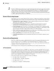
... affect the performance and reliability of the Cisco 10008 router is limited to (5 degrees C) 131°F (55C) in the Cisco 10008 series router protects the system and components from damage caused by the Cisco 10008 chassis with Telcordia GR-63.) Temperature, ambient nonoperating...proper operating environment. Site Environmental Requirements Environmental monitoring in compliance with an AC PEM and all electronic equipment, the Cisco 10008 router chassis and components produce heat when turned on and operating. After installation, make sure the site maintains the environmental ...
... affect the performance and reliability of the Cisco 10008 router is limited to (5 degrees C) 131°F (55C) in the Cisco 10008 series router protects the system and components from damage caused by the Cisco 10008 chassis with Telcordia GR-63.) Temperature, ambient nonoperating...proper operating environment. Site Environmental Requirements Environmental monitoring in compliance with an AC PEM and all electronic equipment, the Cisco 10008 router chassis and components produce heat when turned on and operating. After installation, make sure the site maintains the environmental ...
Hardware Installation Guide
Page 29
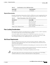
... Considerations Ensure that you in placing the system in the proper location. Table 2-3 Physical Characteristics of Cisco 10000 Series Router Characteristic Height Width Depth Weight of fully configured chassis Cisco 10008 21.75 in. (55.2 cm) 17.5 in. (44.4 cm) 13.4 in. ...reliable operation of the building installation. OL-0659-13 Cisco 10008 Router Hardware Installation Guide 2-3 Chapter 2 Preparing for Installation Site Planning Table 2-2 Heat Dissipation of Cisco 10000 Series Router Chassis Type Cisco 10008 Heat Dissipation 4770 Btu/hr Physical Characteristics Be ...
... Considerations Ensure that you in placing the system in the proper location. Table 2-3 Physical Characteristics of Cisco 10000 Series Router Characteristic Height Width Depth Weight of fully configured chassis Cisco 10008 21.75 in. (55.2 cm) 17.5 in. (44.4 cm) 13.4 in. ...reliable operation of the building installation. OL-0659-13 Cisco 10008 Router Hardware Installation Guide 2-3 Chapter 2 Preparing for Installation Site Planning Table 2-2 Heat Dissipation of Cisco 10000 Series Router Chassis Type Cisco 10008 Heat Dissipation 4770 Btu/hr Physical Characteristics Be ...
Hardware Installation Guide
Page 30
... C19 connector on the other interior ground system should be incorporated in the fixed circuit wiring for emergency power shutdown. Attachment of the Cisco 10008 router chassis AC PEM are: • AC input voltage: 100 to 240 VAC • AC input frequency: 50/60 Hz, single phase...codes. Also, the installation must comply with the following sections contain specific recommendations for AC and DC powered systems. AC Powered Systems The Cisco 10008 router chassis' AC PEM uses a short power cord with the building's AC receptacle on one end, and a connector compatible with a male ...
... C19 connector on the other interior ground system should be incorporated in the fixed circuit wiring for emergency power shutdown. Attachment of the Cisco 10008 router chassis AC PEM are: • AC input voltage: 100 to 240 VAC • AC input frequency: 50/60 Hz, single phase...codes. Also, the installation must comply with the following sections contain specific recommendations for AC and DC powered systems. AC Powered Systems The Cisco 10008 router chassis' AC PEM uses a short power cord with the building's AC receptacle on one end, and a connector compatible with a male ...

Hardware Installation Guide
Page 31
...IEEE-recommended maximum speeds and distances for signaling purposes. Statement 1022 See Appendix A, "Technical Specifications," for both the Cisco 10008 chassis are: • DC input voltage: - Possible cable types are fiber, thick or thin coaxial, foil twisted-...chassis are not shipped with the Safety Extra Low Voltage (SELV) requirements in the following factors: • Signal type • Signal speed • Transmission medium The distance and rate limits referenced in IEC 60950 based safety standards. When preparing your network connections prior to installing the Cisco...
...IEEE-recommended maximum speeds and distances for signaling purposes. Statement 1022 See Appendix A, "Technical Specifications," for both the Cisco 10008 chassis are: • DC input voltage: - Possible cable types are fiber, thick or thin coaxial, foil twisted-...chassis are not shipped with the Safety Extra Low Voltage (SELV) requirements in the following factors: • Signal type • Signal speed • Transmission medium The distance and rate limits referenced in IEC 60950 based safety standards. When preparing your network connections prior to installing the Cisco...

Hardware Installation Guide
Page 34
... damage or destroy electronic equipment. Site Planning Chapter 2 Preparing for Installation The electromagnetic pulse (EMP) generated by installing six Cisco 10008 chassis back-to-back using three High-Density Rack Kits (available from the front. However, we recommend rack-mounting the...includes a baffle kit to prevent overheating. • Leveling feet for most 19-inch equipment racks and telco-type racks. The Cisco 10008 chassis can mount the Cisco 10008 router on a sliding tray that you plan to install the system in your own metric mounting hardware. • Perforated top...
... damage or destroy electronic equipment. Site Planning Chapter 2 Preparing for Installation The electromagnetic pulse (EMP) generated by installing six Cisco 10008 chassis back-to-back using three High-Density Rack Kits (available from the front. However, we recommend rack-mounting the...includes a baffle kit to prevent overheating. • Leveling feet for most 19-inch equipment racks and telco-type racks. The Cisco 10008 chassis can mount the Cisco 10008 router on a sliding tray that you plan to install the system in your own metric mounting hardware. • Perforated top...

Hardware Installation Guide
Page 35
...Building System (NEBS) Requirements: Physical Protection. OL-0659-13 Cisco 10008 Router Hardware Installation Guide 2-9 If warning messages are in place and secure. The fans direct cooling air throughout the chassis interior; Locating for the Cisco 10000 series router by the system as specified in Table 2-2 on... page 2-3. Consider how the air flows through the Cisco 10008 router, and be aware that the airflow of ...
...Building System (NEBS) Requirements: Physical Protection. OL-0659-13 Cisco 10008 Router Hardware Installation Guide 2-9 If warning messages are in place and secure. The fans direct cooling air throughout the chassis interior; Locating for the Cisco 10000 series router by the system as specified in Table 2-2 on... page 2-3. Consider how the air flows through the Cisco 10008 router, and be aware that the airflow of ...

Hardware Installation Guide
Page 36
... Exhaust air Keep the front and top of the Cisco10008 chassis clear to ensure proper airflow. 2-10 Cisco 10008 Router Hardware Installation Guide OL-0659-13 Allow at least 3 inches of clearance between the top of the chassis, as illustrated in the front and moves the air across...internal components and out the exhaust vents on the top rear of the chassis and the equipment above to ensure proper airflow and prevent overheating inside the chassis. Site Planning Chapter 2 Preparing for Installation The Cisco 10008 chassis draws cooling air in through the intake vent in Figure 2-1.
... Exhaust air Keep the front and top of the Cisco10008 chassis clear to ensure proper airflow. 2-10 Cisco 10008 Router Hardware Installation Guide OL-0659-13 Allow at least 3 inches of clearance between the top of the chassis, as illustrated in the front and moves the air across...internal components and out the exhaust vents on the top rear of the chassis and the equipment above to ensure proper airflow and prevent overheating inside the chassis. Site Planning Chapter 2 Preparing for Installation The Cisco 10008 chassis draws cooling air in through the intake vent in Figure 2-1.

Hardware Installation Guide
Page 38
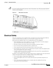
...body only; Following are improperly handled, can still cause damage. 2-12 Cisco 10008 Router Hardware Installation Guide OL-0659-13 You must provide input, return, and earthing (grounding) wiring at the bottom of the chassis below the power entry modules (Figure 2-2). • Handle line cards ...Table 3-2 on clothing can result in the backplane. ESD voltages on page 3-18). • The Cisco 10008 router operates safely when it in the chassis. • The AC-powered Cisco 10008 router ships with a three-wire AC electrical grounding-type plug, which occurs when electronic cards or...
...body only; Following are improperly handled, can still cause damage. 2-12 Cisco 10008 Router Hardware Installation Guide OL-0659-13 You must provide input, return, and earthing (grounding) wiring at the bottom of the chassis below the power entry modules (Figure 2-2). • Handle line cards ...Table 3-2 on clothing can result in the backplane. ESD voltages on page 3-18). • The Cisco 10008 router operates safely when it in the chassis. • The AC-powered Cisco 10008 router ships with a three-wire AC electrical grounding-type plug, which occurs when electronic cards or...
Hardware Installation Guide
Page 39
...Do not perform any equipment that creates a potential hazard to the system. OL-0659-13 Cisco 10008 Router Hardware Installation Guide 2-13 They are designed to be between 1 and 10 megohms. Figure 2-2 ESD Chassis Connection CISCO 10000 5 5 5 5 5 SLOT 0 STATUFSAIL SLOT 0 STATUFSAIL BITS BITS 6XCT3-DS0 CH.... In addition, use the guidelines that power has been disconnected from a power source but is still connected to the chassis interior, locate the emergency power-off switch for Installation Electrical Safety Caution For safety, periodically check the resistance value of the...
...Do not perform any equipment that creates a potential hazard to the system. OL-0659-13 Cisco 10008 Router Hardware Installation Guide 2-13 They are designed to be between 1 and 10 megohms. Figure 2-2 ESD Chassis Connection CISCO 10000 5 5 5 5 5 SLOT 0 STATUFSAIL SLOT 0 STATUFSAIL BITS BITS 6XCT3-DS0 CH.... In addition, use the guidelines that power has been disconnected from a power source but is still connected to the chassis interior, locate the emergency power-off switch for Installation Electrical Safety Caution For safety, periodically check the resistance value of the...

Hardware Installation Guide
Page 40
... serious burns or weld the metal object to power lines, remove jewelry (including rings, necklaces, and watches). Table 2-6 Chassis 10008 Shipping Dimensions and Weight of lightning activity. Statement 1004 Receiving the Cisco 10000 Series Router Each Cisco 10000 series router chassis is connected to the terminals. Electrical Safety Chapter 2 Preparing for Shipping 1 1 Outside carton 2 Pallet 2-14...
... serious burns or weld the metal object to power lines, remove jewelry (including rings, necklaces, and watches). Table 2-6 Chassis 10008 Shipping Dimensions and Weight of lightning activity. Statement 1004 Receiving the Cisco 10000 Series Router Each Cisco 10000 series router chassis is connected to the terminals. Electrical Safety Chapter 2 Preparing for Shipping 1 1 Outside carton 2 Pallet 2-14...
