Hardware Installation Guide
Page 4
... 2-11 Safety 2-11 Preventing Electrostatic Discharge Damage 2-12 Electrical Safety 2-13 Receiving the Cisco 10000 Series Router 2-14 Chassis-Lifting Guidelines 2-15 Required Tools and Equipment 2-16 Verifying Contents After Unpacking 2-16 3 C H A P T E R Installing the Cisco 10008 Router 3-1 Installation Methods 3-1 Rack-Mounting the Chassis 3-2 General Rack Installation Guidelines 3-2 Flush-Mounting in a 19-Inch Rack 3-3 Center-Mounting...
... 2-11 Safety 2-11 Preventing Electrostatic Discharge Damage 2-12 Electrical Safety 2-13 Receiving the Cisco 10000 Series Router 2-14 Chassis-Lifting Guidelines 2-15 Required Tools and Equipment 2-16 Verifying Contents After Unpacking 2-16 3 C H A P T E R Installing the Cisco 10008 Router 3-1 Installation Methods 3-1 Rack-Mounting the Chassis 3-2 General Rack Installation Guidelines 3-2 Flush-Mounting in a 19-Inch Rack 3-3 Center-Mounting...
Hardware Installation Guide
Page 5
...13 Non-Rack Installation 3-11 Connecting the Chassis to Ground 3-13 Recommended Tools and Supplies 3-14 Attaching the Grounding Cable 3-14 Connecting DC Power to the Cisco 10008 Router 3-17 Recommended Tools and Supplies 3-18 Connecting AC Power to the Cisco 10008 Router 3-22 Connecting Alarm Indicators 3-... Modem Connection 3-35 Data Network Cable Connections 3-35 Starting and Configuring the Router 4-1 Powering On the System 4-1 Configuring the Cisco 10008 Router at Startup 4-2 Startup Display 4-3 Basic Configuration Using the Setup Facility 4-3 Using the System Configuration Dialog 4-4 Basic...
...13 Non-Rack Installation 3-11 Connecting the Chassis to Ground 3-13 Recommended Tools and Supplies 3-14 Attaching the Grounding Cable 3-14 Connecting DC Power to the Cisco 10008 Router 3-17 Recommended Tools and Supplies 3-18 Connecting AC Power to the Cisco 10008 Router 3-22 Connecting Alarm Indicators 3-... Modem Connection 3-35 Data Network Cable Connections 3-35 Starting and Configuring the Router 4-1 Powering On the System 4-1 Configuring the Cisco 10008 Router at Startup 4-2 Startup Display 4-3 Basic Configuration Using the Setup Facility 4-3 Using the System Configuration Dialog 4-4 Basic...

Hardware Installation Guide
Page 6
...Cisco 10008 Router 5-1 Required Maintenance Tools 5-3 Shutting Down the System 5-3 Backing Up the PCMCIA Card 5-3 Removing and Replacing Field-Replaceable Units 5-3 Front Cover Procedures 5-4 Removing the Front Cover 5-4 Replacing the Front Cover 5-6 Replacing the Air Filter 5-7 Replacing an Air Filter in a Chassis... that Uses a Filter Tray 5-7 Replacing an Air Filter in a Chassis with Release Tabs 5-9 Replacing the Blower Module 5-10 Installing Power Entry Modules 5-12 Installing a Second ...
...Cisco 10008 Router 5-1 Required Maintenance Tools 5-3 Shutting Down the System 5-3 Backing Up the PCMCIA Card 5-3 Removing and Replacing Field-Replaceable Units 5-3 Front Cover Procedures 5-4 Removing the Front Cover 5-4 Replacing the Front Cover 5-6 Replacing the Air Filter 5-7 Replacing an Air Filter in a Chassis... that Uses a Filter Tray 5-7 Replacing an Air Filter in a Chassis with Release Tabs 5-9 Replacing the Blower Module 5-10 Installing Power Entry Modules 5-12 Installing a Second ...

Hardware Installation Guide
Page 15
...which can be hot-swapped without powering down the chassis OL-0659-13 Cisco 10008 Router Hardware Installation Guide 1-1 This chapter contains the following sections: • Cisco 10008 Router Features, page 1-2 • Cisco 10008 Router Software, page 1-3 • Cisco 10008 Router Hardware Description, page 1-3 Note The ... it is designed to meet and exceed the most stringent ISP requirements for use in this guide depict the original Cisco 10008 chassis. The chassis has eight line card slots and two slots for redundancy using low-speed circuits, and then funnels all of that...
...which can be hot-swapped without powering down the chassis OL-0659-13 Cisco 10008 Router Hardware Installation Guide 1-1 This chapter contains the following sections: • Cisco 10008 Router Features, page 1-2 • Cisco 10008 Router Software, page 1-3 • Cisco 10008 Router Hardware Description, page 1-3 Note The ... it is designed to meet and exceed the most stringent ISP requirements for use in this guide depict the original Cisco 10008 chassis. The chassis has eight line card slots and two slots for redundancy using low-speed circuits, and then funnels all of that...

Hardware Installation Guide
Page 16
...equipment. For channelized OC-12 line cards, this equates to: • 1176 T1 connections per chassis or up to 7056 T1 connections per 7-foot rack. Cisco 10008 Router Features The Cisco 10008 router and power subsystem support the following key features: • 19-inch rack mount, ...for 1+1 Automatic Protection Switching (APS) to accommodate failure of Enhanced High System Availability (EHSA). minor, major, and critical Cisco 10008 Router Hardware Installation Guide 1-2 OL-0659-13 In addition to further increase scalability in future releases. This feature lets you configure the...
...equipment. For channelized OC-12 line cards, this equates to: • 1176 T1 connections per chassis or up to 7056 T1 connections per 7-foot rack. Cisco 10008 Router Features The Cisco 10008 router and power subsystem support the following key features: • 19-inch rack mount, ...for 1+1 Automatic Protection Switching (APS) to accommodate failure of Enhanced High System Availability (EHSA). minor, major, and critical Cisco 10008 Router Hardware Installation Guide 1-2 OL-0659-13 In addition to further increase scalability in future releases. This feature lets you configure the...

Hardware Installation Guide
Page 17
... the front panel. The chassis supports redundant AC or DC power, and contains: • 8 line card slots • 2 processor card slots • Backplane (with rear interconnects) • Capacity for the Cisco 10008 Router For a listing of the Cisco 10008 router. Either slot can...you save the configuration. Configuration information read from the rear, and half-height line card subslot designations on the Cisco 10008 router, see the Cisco 10000 Series Routers Documentation Roadmap, Release Notes. The PRE stores the system configuration in RAM following a system reset, line...
... the front panel. The chassis supports redundant AC or DC power, and contains: • 8 line card slots • 2 processor card slots • Backplane (with rear interconnects) • Capacity for the Cisco 10008 Router For a listing of the Cisco 10008 router. Either slot can...you save the configuration. Configuration information read from the rear, and half-height line card subslot designations on the Cisco 10008 router, see the Cisco 10000 Series Routers Documentation Roadmap, Release Notes. The PRE stores the system configuration in RAM following a system reset, line...

Hardware Installation Guide
Page 18
slot 0A 6 PRE slot 0B 7 Line cards slots 5 to 4 5 PRE - Cisco 10008 Router Hardware Description Figure 1-1 Cisco 10008 Router Chassis-Front View 1 Chapter 1 Cisco 10008 Router Overview 2 3 POWER FAULT MISWIRE LOOP ALARM CARRIER RX TX LINK FANS OK FAFILAUNRE FMAFIULALUNTRI-E sbWreyemhsdteoeonvmnahelsoaihtnnCusduwtAdnarUodepwTeppnIrliaOntcwwgNeioltmlhmoiescnincftauumntre.utsrsaotyr, FAIL FAIL FAIL FAIL 1 CISCO 10000 2 CISCO 10000 3 CISCO 10000 4 CC1IS00C0O0 160C0T030 FAIL LOOP CARALRAIERRM LOOP CARALRAIERRM 0 PO0RT0 CA...
slot 0A 6 PRE slot 0B 7 Line cards slots 5 to 4 5 PRE - Cisco 10008 Router Hardware Description Figure 1-1 Cisco 10008 Router Chassis-Front View 1 Chapter 1 Cisco 10008 Router Overview 2 3 POWER FAULT MISWIRE LOOP ALARM CARRIER RX TX LINK FANS OK FAFILAUNRE FMAFIULALUNTRI-E sbWreyemhsdteoeonvmnahelsoaihtnnCusduwtAdnarUodepwTeppnIrliaOntcwwgNeioltmlhmoiescnincftauumntre.utsrsaotyr, FAIL FAIL FAIL FAIL 1 CISCO 10000 2 CISCO 10000 3 CISCO 10000 4 CC1IS00C0O0 160C0T030 FAIL LOOP CARALRAIERRM LOOP CARALRAIERRM 0 PO0RT0 CA...

Hardware Installation Guide
Page 19
Chapter 1 Cisco 10008 Router Overview Cisco 10008 Router Hardware Description Figure 1-2 BNC Connectors on the Rear of the Chassis 1 2 34 5 6 Tx 0 Tx 0 RX Tx 0 RX RX Tx Tx 1 1 RX RX 7 Tx 2 Tx 2 RX RX Tx 3 RX Tx 3 RX Tx 4 RX Tx 4 RX Tx 5 Tx 5 RX RX 8 Tx 6 Tx 6 RX RX Tx 7 RX Tx 7 RX 126111 1 Line card slot 8 2 Line cards slot 5 3 Blower module 4 Line card slot 4 5 Line card slot 1 6 Power supply 7 Half-height line card subslot 0 8 Half-height line card subslot 1 OL-0659-13 Cisco 10008 Router Hardware Installation Guide 1-5
Chapter 1 Cisco 10008 Router Overview Cisco 10008 Router Hardware Description Figure 1-2 BNC Connectors on the Rear of the Chassis 1 2 34 5 6 Tx 0 Tx 0 RX Tx 0 RX RX Tx Tx 1 1 RX RX 7 Tx 2 Tx 2 RX RX Tx 3 RX Tx 3 RX Tx 4 RX Tx 4 RX Tx 5 Tx 5 RX RX 8 Tx 6 Tx 6 RX RX Tx 7 RX Tx 7 RX 126111 1 Line card slot 8 2 Line cards slot 5 3 Blower module 4 Line card slot 4 5 Line card slot 1 6 Power supply 7 Half-height line card subslot 0 8 Half-height line card subslot 1 OL-0659-13 Cisco 10008 Router Hardware Installation Guide 1-5

Hardware Installation Guide
Page 20
... four fans to supply cooling air to a connector on the DC PEM. Table 1-1 describes the LEDs on the chassis. 1. Cisco 10008 Router Hardware Description Chapter 1 Cisco 10008 Router Overview The Cisco 10008 chassis is designed for more than a few minutes to the chassis electronics (Figure 1-4). Four internal fans draw cooling air into the front of the...
... four fans to supply cooling air to a connector on the DC PEM. Table 1-1 describes the LEDs on the chassis. 1. Cisco 10008 Router Hardware Description Chapter 1 Cisco 10008 Router Overview The Cisco 10008 chassis is designed for more than a few minutes to the chassis electronics (Figure 1-4). Four internal fans draw cooling air into the front of the...

Hardware Installation Guide
Page 27
...; Preventing Electrostatic Discharge Damage, page 2-12 • Electrical Safety, page 2-13 • Electrical Safety, page 2-13 • Receiving the Cisco 10000 Series Router, page 2-14 • Required Tools and Equipment, page 2-16 Site Planning This section contains site planning information, and will help...Guidelines, page 2-8 • Rack-Mounting and Location Guidelines • Site Planning Checklist OL-0659-13 Cisco 10008 Router Hardware Installation Guide 2-1 Keep the chassis in place at your installation site • The equipment required to install the router • The ...
...; Preventing Electrostatic Discharge Damage, page 2-12 • Electrical Safety, page 2-13 • Electrical Safety, page 2-13 • Receiving the Cisco 10000 Series Router, page 2-14 • Required Tools and Equipment, page 2-16 Site Planning This section contains site planning information, and will help...Guidelines, page 2-8 • Rack-Mounting and Location Guidelines • Site Planning Checklist OL-0659-13 Cisco 10008 Router Hardware Installation Guide 2-1 Keep the chassis in place at your installation site • The equipment required to install the router • The ...

Hardware Installation Guide
Page 28
...;F (55C) in compliance with an AC PEM and all electronic equipment, the Cisco 10008 router chassis and components produce heat when turned on and operating. Table 2-1 Cisco 10008 Router Environmental Tolerances Environmental Characteristic Minimum Temperature, ambient operating 41 degrees F (...After installation, make sure the site maintains the environmental characteristics as shown in the Cisco 10008 series router protects the system and components from damage caused by the Cisco 10008 chassis with Telcordia GR-63.) Temperature, ambient nonoperating and storage -40 degrees F (-40...
...;F (55C) in compliance with an AC PEM and all electronic equipment, the Cisco 10008 router chassis and components produce heat when turned on and operating. Table 2-1 Cisco 10008 Router Environmental Tolerances Environmental Characteristic Minimum Temperature, ambient operating 41 degrees F (...After installation, make sure the site maintains the environmental characteristics as shown in the Cisco 10008 series router protects the system and components from damage caused by the Cisco 10008 chassis with Telcordia GR-63.) Temperature, ambient nonoperating and storage -40 degrees F (-40...
Hardware Installation Guide
Page 29
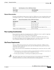
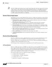
...Installation Site Planning Table 2-2 Heat Dissipation of Cisco 10000 Series Router Chassis Type Cisco 10008 Heat Dissipation 4770 Btu/hr Physical Characteristics Be familiar with national and local wiring regulations. Site Power Requirements The Cisco 10008 router has specific power and electrical ...overcurrent) protection, to be provided as part of the Cisco 10008 router to assist you are receiving clean power. Table 2-3 Physical Characteristics of Cisco 10000 Series Router Characteristic Height Width Depth Weight of fully configured chassis Cisco 10008 21.75 in. (55.2 cm) 17.5 ...
...Installation Site Planning Table 2-2 Heat Dissipation of Cisco 10000 Series Router Chassis Type Cisco 10008 Heat Dissipation 4770 Btu/hr Physical Characteristics Be familiar with national and local wiring regulations. Site Power Requirements The Cisco 10008 router has specific power and electrical ...overcurrent) protection, to be provided as part of the Cisco 10008 router to assist you are receiving clean power. Table 2-3 Physical Characteristics of Cisco 10000 Series Router Characteristic Height Width Depth Weight of fully configured chassis Cisco 10008 21.75 in. (55.2 cm) 17.5 ...
Hardware Installation Guide
Page 30
...PEM to a central office or other end. The ground bond fastening hardware should be of the chassis ground to avoid compromising the power redundancy feature. The electrical ratings of the Cisco 10008 router chassis AC PEM are: • AC input voltage: 100 to 240 VAC • AC input ... ensure compatibility with the building's AC receptacle. Ensure the equipment grounding is approved for AC and DC powered systems. AC Powered Systems The Cisco 10008 router chassis' AC PEM uses a short power cord with a male IEC 320 C20 AC inlet power connector and a strain relief device (canoe)....
...PEM to a central office or other end. The ground bond fastening hardware should be of the chassis ground to avoid compromising the power redundancy feature. The electrical ratings of the Cisco 10008 router chassis AC PEM are: • AC input voltage: 100 to 240 VAC • AC input ... ensure compatibility with the building's AC receptacle. Ensure the equipment grounding is approved for AC and DC powered systems. AC Powered Systems The Cisco 10008 router chassis' AC PEM uses a short power cord with a male IEC 320 C20 AC inlet power connector and a strain relief device (canoe)....

Hardware Installation Guide
Page 31
.... Before you need, such as a guideline in planning your site for network connections to installing the Cisco 10008 router. The extent of the DC PEMs for both the Cisco 10008 chassis are: • DC input voltage: - Possible cable types are fiber, thick or thin coaxial, ...Site Planning DC Powered Systems The DC PEMs for the Cisco 10008 router chassis are not shipped with the Safety Extra Low Voltage (SELV) requirements in IEC 60950 based safety standards. Also consider any additional interface equipment you install the Cisco 10008 series router, have terminal blocks to -60 ...
.... Before you need, such as a guideline in planning your site for network connections to installing the Cisco 10008 router. The extent of the DC PEMs for both the Cisco 10008 chassis are: • DC input voltage: - Possible cable types are fiber, thick or thin coaxial, ...Site Planning DC Powered Systems The DC PEMs for the Cisco 10008 router chassis are not shipped with the Safety Extra Low Voltage (SELV) requirements in IEC 60950 based safety standards. Also consider any additional interface equipment you install the Cisco 10008 series router, have terminal blocks to -60 ...

Hardware Installation Guide
Page 34
...includes the necessary rack-mounting hardware which is shipped with front and rear RETMA rails installed Cisco 10008 Router Hardware Installation Guide 2-8 OL-0659-13 The Cisco 10008 chassis can couple enough energy into unshielded conductors to install the system in has metric-threaded rails... mounting rails, or mid-mounted to -back 10008 chassis on mid-mounting, see Chapter 3, "Installing the Cisco 10008 Router." You can accommodate three Cisco 10008 chassis mounted from Cisco). The High-Density Rack Kit can mount the Cisco 10008 router on an equipment shelf or tabletop. However,...
...includes the necessary rack-mounting hardware which is shipped with front and rear RETMA rails installed Cisco 10008 Router Hardware Installation Guide 2-8 OL-0659-13 The Cisco 10008 chassis can couple enough energy into unshielded conductors to install the system in has metric-threaded rails... mounting rails, or mid-mounted to -back 10008 chassis on mid-mounting, see Chapter 3, "Installing the Cisco 10008 Router." You can accommodate three Cisco 10008 chassis mounted from Cisco). The High-Density Rack Kit can mount the Cisco 10008 router on an equipment shelf or tabletop. However,...

Hardware Installation Guide
Page 35
...the internal system status. Temperature sensors on page 2-2. If warning messages are in place and secure. Avoid locating the Cisco 10008 router in a location in which the chassis air intake vents could affect access to the routers cards. Locating for Easy Maintenance Keep at or near the bottom...the front of clear space in the following sections. it at least 3 feet of the chassis-3 to 4 ft (91.44 cm to compensate for the heat dissipated by following clearances for the Cisco 10000 series router by the system as described in front and behind the rack. The fans direct ...
...the internal system status. Temperature sensors on page 2-2. If warning messages are in place and secure. Avoid locating the Cisco 10008 router in a location in which the chassis air intake vents could affect access to the routers cards. Locating for Easy Maintenance Keep at or near the bottom...the front of clear space in the following sections. it at least 3 feet of the chassis-3 to 4 ft (91.44 cm to compensate for the heat dissipated by following clearances for the Cisco 10000 series router by the system as described in front and behind the rack. The fans direct ...

Hardware Installation Guide
Page 36
...the air across the internal components and out the exhaust vents on the top rear of the Cisco10008 chassis clear to ensure proper airflow. 2-10 Cisco 10008 Router Hardware Installation Guide OL-0659-13 Allow at least 3 inches of clearance between the ...top of the chassis and the equipment above to ensure proper airflow and prevent overheating inside the chassis. Figure 2-1 Cisco 10008 Chassis Airflow 1 2 8 3 7 132843 4 5 6 1 Blower module (fans) 2 Top 3 Front 4 Ambient air intake 5...
...the air across the internal components and out the exhaust vents on the top rear of the Cisco10008 chassis clear to ensure proper airflow. 2-10 Cisco 10008 Router Hardware Installation Guide OL-0659-13 Allow at least 3 inches of clearance between the ...top of the chassis and the equipment above to ensure proper airflow and prevent overheating inside the chassis. Figure 2-1 Cisco 10008 Chassis Airflow 1 2 8 3 7 132843 4 5 6 1 Blower module (fans) 2 Top 3 Front 4 Ambient air intake 5...

Hardware Installation Guide
Page 38
...module, provide proper grounding for preventing ESD damage: • Always use an antistatic strap each time you are integral components of the chassis below the power entry modules (Figure 2-2). • Handle line cards by the edges only; The wrist strap protects the card from ...a three-wire AC electrical grounding-type plug, which occurs when electronic cards or components are properly seated in the chassis. • The AC-powered Cisco 10008 router ships with its marked electrical ratings and product usage instructions. Warning Only trained and qualified personnel should be...
...module, provide proper grounding for preventing ESD damage: • Always use an antistatic strap each time you are integral components of the chassis below the power entry modules (Figure 2-2). • Handle line cards by the edges only; The wrist strap protects the card from ...a three-wire AC electrical grounding-type plug, which occurs when electronic cards or components are properly seated in the chassis. • The AC-powered Cisco 10008 router ships with its marked electrical ratings and product usage instructions. Warning Only trained and qualified personnel should be...
Hardware Installation Guide
Page 39
... these basic guidelines when you are working with any equipment that is disconnected from a power source but is still connected to the chassis interior, locate the emergency power-off switch for wet locations. • Never touch uninsulated telephone wires or terminals unless the telephone line... storm. • Never install telephone jacks in which you are hot-swappable. They are designed to be between 1 and 10 megohms. Figure 2-2 ESD Chassis Connection CISCO 10000 5 5 5 5 5 SLOT 0 STATUFSAIL SLOT 0 STATUFSAIL BITS BITS 6XCT3-DS0 CH OC-12-DSO SM-IR OC-12/STM-4 POS SM-IR ...
... these basic guidelines when you are working with any equipment that is disconnected from a power source but is still connected to the chassis interior, locate the emergency power-off switch for wet locations. • Never touch uninsulated telephone wires or terminals unless the telephone line... storm. • Never install telephone jacks in which you are hot-swappable. They are designed to be between 1 and 10 megohms. Figure 2-2 ESD Chassis Connection CISCO 10000 5 5 5 5 5 SLOT 0 STATUFSAIL SLOT 0 STATUFSAIL BITS BITS 6XCT3-DS0 CH OC-12-DSO SM-IR OC-12/STM-4 POS SM-IR ...

Hardware Installation Guide
Page 40
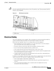
... Warning Read the installation instructions before you work on equipment that is connected to the terminals. Statement 1004 Receiving the Cisco 10000 Series Router Each Cisco 10000 series router chassis is shipped in . (61 cm) Figure 2-3 Cisco 10000 Series Router Packaged for Installation • Use caution when installing or modifying telephone lines. Warning Do not work on...
... Warning Read the installation instructions before you work on equipment that is connected to the terminals. Statement 1004 Receiving the Cisco 10000 Series Router Each Cisco 10000 series router chassis is shipped in . (61 cm) Figure 2-3 Cisco 10000 Series Router Packaged for Installation • Use caution when installing or modifying telephone lines. Warning Do not work on...
