Hardware Installation Guide
Page 4
... Cabling Guidelines 2-5 Interference Considerations 2-6 Asynchronous Terminal Connections 2-6 Ethernet Connections 2-6 Setting Up Fiber-Optic Connections 2-7 Interference Considerations 2-7 Rack-Mounting and Location Guidelines 2-8 Rack Selection Guidelines 2-8 Rack Configuration Guidelines 2-8 Rack Placement Guidelines 2-9 Site Planning Checklist 2-11 Safety 2-11 Preventing Electrostatic Discharge Damage 2-12 Electrical Safety 2-13 Receiving the Cisco 10000 Series Router 2-14 Chassis-Lifting Guidelines 2-15...
... Cabling Guidelines 2-5 Interference Considerations 2-6 Asynchronous Terminal Connections 2-6 Ethernet Connections 2-6 Setting Up Fiber-Optic Connections 2-7 Interference Considerations 2-7 Rack-Mounting and Location Guidelines 2-8 Rack Selection Guidelines 2-8 Rack Configuration Guidelines 2-8 Rack Placement Guidelines 2-9 Site Planning Checklist 2-11 Safety 2-11 Preventing Electrostatic Discharge Damage 2-12 Electrical Safety 2-13 Receiving the Cisco 10000 Series Router 2-14 Chassis-Lifting Guidelines 2-15...
Hardware Installation Guide
Page 5
... Recommended Tools and Supplies 3-14 Attaching the Grounding Cable 3-14 Connecting DC Power to the Cisco 10008 Router 3-17 Recommended Tools and Supplies 3-18 Connecting AC Power to the Cisco 10008 Router 3-22 Connecting Alarm Indicators 3-26 Connecting a Video Terminal to the PRE Console Port 3-30 Connecting Network Management and Signal System Cables 3-32 Ethernet Network Management...
... Recommended Tools and Supplies 3-14 Attaching the Grounding Cable 3-14 Connecting DC Power to the Cisco 10008 Router 3-17 Recommended Tools and Supplies 3-18 Connecting AC Power to the Cisco 10008 Router 3-22 Connecting Alarm Indicators 3-26 Connecting a Video Terminal to the PRE Console Port 3-30 Connecting Network Management and Signal System Cables 3-32 Ethernet Network Management...

Hardware Installation Guide
Page 6
... P T E R A A P P E N D I X B A P P E N D I X GLOSSARY INDEX Troubleshooting the Console Port Serial Connection 4-14 Maintaining the Cisco 10008 Router 5-1 Required Maintenance Tools 5-3 Shutting Down the System 5-3 Backing Up the PCMCIA Card 5-3 Removing and Replacing Field-Replaceable Units 5-3 Front Cover Procedures 5-4... 5-12 Installing a Second DC PEM 5-12 Replacing a DC PEM 5-20 Installing a Second AC PEM 5-24 Replacing an AC PEM 5-28 Connecting Alarm Indicators 5-32 Removing and Replacing the PRE 5-36 Removing and Installing a PCMCIA Flash Memory Card 5-44 Upgrading SDRAM on the PRE 5-46...
... P T E R A A P P E N D I X B A P P E N D I X GLOSSARY INDEX Troubleshooting the Console Port Serial Connection 4-14 Maintaining the Cisco 10008 Router 5-1 Required Maintenance Tools 5-3 Shutting Down the System 5-3 Backing Up the PCMCIA Card 5-3 Removing and Replacing Field-Replaceable Units 5-3 Front Cover Procedures 5-4... 5-12 Installing a Second DC PEM 5-12 Replacing a DC PEM 5-20 Installing a Second AC PEM 5-24 Replacing an AC PEM 5-28 Connecting Alarm Indicators 5-32 Removing and Replacing the PRE 5-36 Removing and Installing a PCMCIA Flash Memory Card 5-44 Upgrading SDRAM on the PRE 5-46...

Hardware Installation Guide
Page 8
... system. • Chapter 2, "Preparing for Installation," is a preparatory chapter that you should perform before the installation. • Chapter 3, "Installing the Cisco 10008 Router," provides information for installing the router hardware, connecting system cables, and verifying system operation. • Chapter 4, "Starting and Configuring the Router," provides information for starting up the router. You...
... system. • Chapter 2, "Preparing for Installation," is a preparatory chapter that you should perform before the installation. • Chapter 3, "Installing the Cisco 10008 Router," provides information for installing the router hardware, connecting system cables, and verifying system operation. • Chapter 4, "Starting and Configuring the Router," provides information for starting up the router. You...

Hardware Installation Guide
Page 15
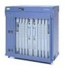
...features include: • Redundant blowers • Redundant power (AC or DC) • Redundant PREs • Pairs of DS1/T1 connections. The Cisco 10008 router is designed to large numbers of high-speed trunk interfaces. The chassis has eight line card slots and two slots for use ...page 1-3 Note The illustrations in a telco central office environment, it is a high capacity Layer 3 router optimized to support selected Cisco IOS software services at wire speed performance on thousands of Synchronous Optical Network (SONET) interfaces which can be hot-swapped without powering ...
...features include: • Redundant blowers • Redundant power (AC or DC) • Redundant PREs • Pairs of DS1/T1 connections. The Cisco 10008 router is designed to large numbers of high-speed trunk interfaces. The chassis has eight line card slots and two slots for use ...page 1-3 Note The illustrations in a telco central office environment, it is a high capacity Layer 3 router optimized to support selected Cisco IOS software services at wire speed performance on thousands of Synchronous Optical Network (SONET) interfaces which can be hot-swapped without powering ...

Hardware Installation Guide
Page 16
...with two PREs. For channelized OC-12 line cards, this equates to: • 1176 T1 connections per chassis or up to 7056 T1 connections per 7-foot rack. Cisco 10008 Router Features The Cisco 10008 router and power subsystem support the following key features: • 19-inch rack mount, 12...-inch depth • 21.75-inch height (3 units per 7-foot rack. minor, major, and critical Cisco 10008 Router Hardware ...
...with two PREs. For channelized OC-12 line cards, this equates to: • 1176 T1 connections per chassis or up to 7056 T1 connections per 7-foot rack. Cisco 10008 Router Features The Cisco 10008 router and power subsystem support the following key features: • 19-inch rack mount, 12...-inch depth • 21.75-inch height (3 units per 7-foot rack. minor, major, and critical Cisco 10008 Router Hardware ...

Hardware Installation Guide
Page 20
...Although the blower module supports hot-swapping and can be replaced without interruption to a connector on the DC PEM. Cisco 10008 Router Hardware Installation Guide 1-6 OL-0659-13 Power Entry Modules The DC PEM provides filtering and supplies DC power... FANS OK FAN FAILURE MULTIFAN FAILURE WrbseyemhsdetoeonvmnahelsoaihtnnCusduwtAdnarUodepwTeppnIrliaOntcwwgNeioltmlhmoiescnincftauumntre.utsrsaotyr, The blower module is located at the top of the chassis and connects to system operation, do not power down the system without the blower unit for mounting in the rear of the ...
...Although the blower module supports hot-swapping and can be replaced without interruption to a connector on the DC PEM. Cisco 10008 Router Hardware Installation Guide 1-6 OL-0659-13 Power Entry Modules The DC PEM provides filtering and supplies DC power... FANS OK FAN FAILURE MULTIFAN FAILURE WrbseyemhsdetoeonvmnahelsoaihtnnCusduwtAdnarUodepwTeppnIrliaOntcwwgNeioltmlhmoiescnincftauumntre.utsrsaotyr, The blower module is located at the top of the chassis and connects to system operation, do not power down the system without the blower unit for mounting in the rear of the ...

Hardware Installation Guide
Page 21
... VAC) to the PEM. Table 1-2 describes the LEDs on page 4-12). The AC PEM provides power conversion directly from the VAC connection power cable to the power cord attached to the -48 VDC used internally by the system (Figure 1-5). AC power is operational. OL-0659...-13 Cisco 10008 Router Hardware Installation Guide 1-7 The PEM is not operating correctly (see the Cisco 10000 Series ESR Troubleshooting Guide). -48V and RTN (+) wires are reversed (see the "Troubleshooting Installation Problems" ...
... VAC) to the PEM. Table 1-2 describes the LEDs on page 4-12). The AC PEM provides power conversion directly from the VAC connection power cable to the power cord attached to the -48 VDC used internally by the system (Figure 1-5). AC power is operational. OL-0659...-13 Cisco 10008 Router Hardware Installation Guide 1-7 The PEM is not operating correctly (see the Cisco 10000 Series ESR Troubleshooting Guide). -48V and RTN (+) wires are reversed (see the "Troubleshooting Installation Problems" ...

Hardware Installation Guide
Page 23
... connectors (see Figure 1-6): • Console port (CON)-This asynchronous EIA/TIA-232 serial port is used to connect a terminal to the PRE for local administrative access. • Auxiliary port (AUX)-This asynchronous EIA/TIA-232 serial port is ... high throughput while still allowing substantial feature processing. Figure 1-6 Performance Routing Engine, Product Number ESR-PRE, Front Panel PERFORMANCE ROUTING ENGINE CISCO 10000 CONSOLE AUX ELAITCNHTKIEVIRTNYET SLOT SLOT 1 0 Figure 1-7 shows the front panel of the Performance Routing Engine, product number ESR-PRE1. ALARMS...
... connectors (see Figure 1-6): • Console port (CON)-This asynchronous EIA/TIA-232 serial port is used to connect a terminal to the PRE for local administrative access. • Auxiliary port (AUX)-This asynchronous EIA/TIA-232 serial port is ... high throughput while still allowing substantial feature processing. Figure 1-6 Performance Routing Engine, Product Number ESR-PRE, Front Panel PERFORMANCE ROUTING ENGINE CISCO 10000 CONSOLE AUX ELAITCNHTKIEVIRTNYET SLOT SLOT 1 0 Figure 1-7 shows the front panel of the Performance Routing Engine, product number ESR-PRE1. ALARMS...

Hardware Installation Guide
Page 24
... into three categories: • alarms • status • failure Alarm relay contacts on page 5-45 for more information about alarm connections. the port is corrected. PRE LED Indicators and Switches LEDs on the PRE. Table 1-3 describes the LEDs and switch on the front... active. This allows critical, major, and minor alarms generated by the Cisco 10008 router to a site alarm maintenance system. See "Figure 5-47Removing the PCMCIA Flash Card" section on the Cisco 10008 router let you connect the router to be displayed on the flash memory card. Table 1-3...
... into three categories: • alarms • status • failure Alarm relay contacts on page 5-45 for more information about alarm connections. the port is corrected. PRE LED Indicators and Switches LEDs on the PRE. Table 1-3 describes the LEDs and switch on the front... active. This allows critical, major, and minor alarms generated by the Cisco 10008 router to a site alarm maintenance system. See "Figure 5-47Removing the PCMCIA Flash Card" section on the Cisco 10008 router let you connect the router to be displayed on the flash memory card. Table 1-3...
Hardware Installation Guide
Page 29
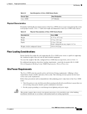
...the combined weight of the rack and all other installed equipment. Follow these precautions and recommendations when planning power connections to the Cisco 10008 router: • Check the power at your site before installation and periodically after installation to these ... to assist you are receiving clean power. Chapter 2 Preparing for Installation Site Planning Table 2-2 Heat Dissipation of Cisco 10000 Series Router Chassis Type Cisco 10008 Heat Dissipation 4770 Btu/hr Physical Characteristics Be familiar with national and local wiring regulations. Table 2-3 shows ...
...the combined weight of the rack and all other installed equipment. Follow these precautions and recommendations when planning power connections to the Cisco 10008 router: • Check the power at your site before installation and periodically after installation to these ... to assist you are receiving clean power. Chapter 2 Preparing for Installation Site Planning Table 2-2 Heat Dissipation of Cisco 10000 Series Router Chassis Type Cisco 10008 Heat Dissipation 4770 Btu/hr Physical Characteristics Be familiar with national and local wiring regulations. Table 2-3 shows ...

Hardware Installation Guide
Page 31
...medium The distance and rate limits referenced in planning your site for network connections to the DC source. OL-0659-13 Cisco 10008 Router Hardware Installation Guide 2-5 Statement 1022 See Appendix A, "Technical ...connections depend in part on hand. Use this information as transceivers, hubs, switches, modems, channel service units (CSUs), or data service units (DSUs). Nominal range -48 VDC to attach building's input, return, and earthing (ground) wiring. The DC power source must incorporate a readily accessible 2-poled disconnect device in IEC 60950 based...
...medium The distance and rate limits referenced in planning your site for network connections to the DC source. OL-0659-13 Cisco 10008 Router Hardware Installation Guide 2-5 Statement 1022 See Appendix A, "Technical ...connections depend in part on hand. Use this information as transceivers, hubs, switches, modems, channel service units (CSUs), or data service units (DSUs). Nominal range -48 VDC to attach building's input, return, and earthing (ground) wiring. The DC power source must incorporate a readily accessible 2-poled disconnect device in IEC 60950 based...

Hardware Installation Guide
Page 32
... standard 802.3, but industry experience has shown that connections remain reliable at your plant wiring with one ground conductor for local console access. Cisco 10008 Router Hardware Installation Guide 2-6 OL-0659-13 Asynchronous Terminal Connections The PRE provides a Console Port to exceed the... distances and speeds recommended by the IEEE, you choose to connect a terminal or computer for each data...
... standard 802.3, but industry experience has shown that connections remain reliable at your plant wiring with one ground conductor for local console access. Cisco 10008 Router Hardware Installation Guide 2-6 OL-0659-13 Asynchronous Terminal Connections The PRE provides a Console Port to exceed the... distances and speeds recommended by the IEEE, you choose to connect a terminal or computer for each data...

Hardware Installation Guide
Page 33
...each data signal. If you use a high-quality twisted-pair cable with a good distribution of other fiber-optic specifications, see the Cisco 10000 Series Routers Line Card Hardware Installation Guide. However, you should consider the effect that can cause data errors or damage to minimize ...half duplex Full and half duplex IEEE Maximum Distance Between Stations 328 ft (100 m) 328 ft (100 m) Setting Up Fiber-Optic Connections For other equipment. The typical sources of interference and how to the equipment. Electromagnetic Interference All equipment powered by causing power surges ...
...each data signal. If you use a high-quality twisted-pair cable with a good distribution of other fiber-optic specifications, see the Cisco 10000 Series Routers Line Card Hardware Installation Guide. However, you should consider the effect that can cause data errors or damage to minimize ...half duplex Full and half duplex IEEE Maximum Distance Between Stations 328 ft (100 m) 328 ft (100 m) Setting Up Fiber-Optic Connections For other equipment. The typical sources of interference and how to the equipment. Electromagnetic Interference All equipment powered by causing power surges ...

Hardware Installation Guide
Page 35
... has enough airflow to check the internal system status. Consider how the air flows through the Cisco 10008 router, and be aware that you plan the equipment locations and connections: • Use the show environment command regularly to keep the system operating within the environmental...Planning Rack Placement Guidelines The placement of the rack can redirect the airflow away from active components. Choose a proper location for the Cisco 10000 series router by the system as described in the rack, consider installing it provides warnings for high temperature and creates reports on ...
... has enough airflow to check the internal system status. Consider how the air flows through the Cisco 10008 router, and be aware that you plan the equipment locations and connections: • Use the show environment command regularly to keep the system operating within the environmental...Planning Rack Placement Guidelines The placement of the rack can redirect the airflow away from active components. Choose a proper location for the Cisco 10000 series router by the system as described in the rack, consider installing it provides warnings for high temperature and creates reports on ...

Hardware Installation Guide
Page 37
...Checklist Site Planning Requirements The site meets the environmental requirements (Site Environmental Requirements, page 2-2). The Cisco 10008 router Ethernet cabling distances are within limitations (Ethernet Connections, page 2-6). Interference Considerations, page 2-7 have been studied, and an EMI/RFI expert has ... 2-9). In the United States, this appendix. The equipment rack in the Regulatory Compliance and Safety Information for the Cisco 10000 Series Routers document, before installing, configuring, or performing maintenance on the product. However, these guidelines may not cover...
...Checklist Site Planning Requirements The site meets the environmental requirements (Site Environmental Requirements, page 2-2). The Cisco 10008 router Ethernet cabling distances are within limitations (Ethernet Connections, page 2-6). Interference Considerations, page 2-7 have been studied, and an EMI/RFI expert has ... 2-9). In the United States, this appendix. The equipment rack in the Regulatory Compliance and Safety Information for the Cisco 10000 Series Routers document, before installing, configuring, or performing maintenance on the product. However, these guidelines may not cover...

Hardware Installation Guide
Page 38
...wire AC electrical grounding-type plug, which occurs when electronic cards or components are improperly handled, can still cause damage. 2-12 Cisco 10008 Router Hardware Installation Guide OL-0659-13 Ensure the equipment grounding is in compliance with local and national electrical codes. •...Discharge Damage Electrostatic discharge (ESD) damage, which fits into a grounding-type power outlet only. Before removing a card from the chassis, connect the equipment end of the chassis below the power entry modules (Figure 2-2). • Handle line cards by the edges only; Warning Only...
...wire AC electrical grounding-type plug, which occurs when electronic cards or components are improperly handled, can still cause damage. 2-12 Cisco 10008 Router Hardware Installation Guide OL-0659-13 Ensure the equipment grounding is in compliance with local and national electrical codes. •...Discharge Damage Electrostatic discharge (ESD) damage, which fits into a grounding-type power outlet only. Before removing a card from the chassis, connect the equipment end of the chassis below the power entry modules (Figure 2-2). • Handle line cards by the edges only; Warning Only...
Hardware Installation Guide
Page 39
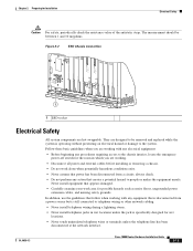
...not perform any procedures requiring access to people or makes the equipment unsafe. The measurement should be between 1 and 10 megohms. Figure 2-2 ESD Chassis Connection CISCO 10000 5 5 5 5 5 SLOT 0 STATUFSAIL SLOT 0 STATUFSAIL BITS BITS 6XCT3-DS0 CH OC-12-DSO SM-IR OC-12/STM-4 POS SM-... ESD socket Electrical Safety All system components are designed to be removed and replaced while the system is still connected to the system. OL-0659-13 Cisco 10008 Router Hardware Installation Guide 2-13 Follow these basic guidelines when you are working with any electrical equipment: ...
...not perform any procedures requiring access to people or makes the equipment unsafe. The measurement should be between 1 and 10 megohms. Figure 2-2 ESD Chassis Connection CISCO 10000 5 5 5 5 5 SLOT 0 STATUFSAIL SLOT 0 STATUFSAIL BITS BITS 6XCT3-DS0 CH OC-12-DSO SM-IR OC-12/STM-4 POS SM-... ESD socket Electrical Safety All system components are designed to be removed and replaced while the system is still connected to the system. OL-0659-13 Cisco 10008 Router Hardware Installation Guide 2-13 Follow these basic guidelines when you are working with any electrical equipment: ...

Hardware Installation Guide
Page 40
... 43 Warning Read the installation instructions before you work on equipment that is connected to a pallet as illustrated in Figure 2-3, and includes the physical dimensions listed in . (61 cm) Figure 2-3 Cisco 10000 Series Router Packaged for Installation • Use caution when installing or modifying telephone... Router Each Cisco 10000 series router chassis is shipped in a container that is strapped to power lines, remove jewelry (including rings, necklaces, and watches). Metal objects will heat up when connected to power and ground and the heat can cause serious burns or weld...
... 43 Warning Read the installation instructions before you work on equipment that is connected to a pallet as illustrated in Figure 2-3, and includes the physical dimensions listed in . (61 cm) Figure 2-3 Cisco 10000 Series Router Packaged for Installation • Use caution when installing or modifying telephone... Router Each Cisco 10000 series router chassis is shipped in a container that is strapped to power lines, remove jewelry (including rings, necklaces, and watches). Metal objects will heat up when connected to power and ground and the heat can cause serious burns or weld...

Hardware Installation Guide
Page 41
...CISCO 10000 2 CISCO 10000 3 CISCO 10000 4 CISCO 10000 FAIL FAIL FAIL FAIL LOOP CARALRAIERRM LOOP CARALRAIERRM 0 0 1 1 2 2 SSLLOOTT01 SSLLOOTT01 0A PROCESSOR ONLY0B CISCO 10000 CISCO 10000 CONSOLE AUX ELAICTNHTKIEVRITNYET CONSOLE AUX ELAICTNHTKIEVRITNYET LOOP CARALRAIERRM LOOP CARALRAIERRM LOOP CARALRAIERRM FAIL FAIL FAIL 5 CISCO 10000 0 6 CISCO 10000 0 7 CISCO 10000 0 1 1 1 3 3 2 2 2 4 4 5 5 3 3 3 4 4 4 5 5 5 FAIL 8 CISCO 10000...chassis later to accommodate power sources and network connections. OL-0659-13 Cisco 10008 Router Hardware Installation Guide 2-15 The ...
...CISCO 10000 2 CISCO 10000 3 CISCO 10000 4 CISCO 10000 FAIL FAIL FAIL FAIL LOOP CARALRAIERRM LOOP CARALRAIERRM 0 0 1 1 2 2 SSLLOOTT01 SSLLOOTT01 0A PROCESSOR ONLY0B CISCO 10000 CISCO 10000 CONSOLE AUX ELAICTNHTKIEVRITNYET CONSOLE AUX ELAICTNHTKIEVRITNYET LOOP CARALRAIERRM LOOP CARALRAIERRM LOOP CARALRAIERRM FAIL FAIL FAIL 5 CISCO 10000 0 6 CISCO 10000 0 7 CISCO 10000 0 1 1 1 3 3 2 2 2 4 4 5 5 3 3 3 4 4 4 5 5 5 FAIL 8 CISCO 10000...chassis later to accommodate power sources and network connections. OL-0659-13 Cisco 10008 Router Hardware Installation Guide 2-15 The ...


