

Administration Guide
Page 2
...are the property of the word partner does not imply a partnership relationship between Cisco and any other company. (1002R) Cisco TelePresence System Release 1.6 Administration Guide © 2010 Cisco Systems, Inc. All other countries. IF YOU ARE UNABLE TO LOCATE THE SOFTWARE... LICENSE OR LIMITED WARRANTY, CONTACT YOUR CISCO REPRESENTATIVE FOR A COPY. USERS MUST TAKE FULL RESPONSIBILITY FOR ...
...are the property of the word partner does not imply a partnership relationship between Cisco and any other company. (1002R) Cisco TelePresence System Release 1.6 Administration Guide © 2010 Cisco Systems, Inc. All other countries. IF YOU ARE UNABLE TO LOCATE THE SOFTWARE... LICENSE OR LIMITED WARRANTY, CONTACT YOUR CISCO REPRESENTATIVE FOR A COPY. USERS MUST TAKE FULL RESPONSIBILITY FOR ...

Administration Guide
Page 17
...; Make recordings public so that anyone with access to a CTS with others for more information. When enabled, preference is controlled by checking the Enable Audio Echo Cancellation (AEC) check-box in the Product Specific Configuration Layout section in the Cisco TelePresence System User Guide on the CTRS. • Share recordings with CTRS functionality; See...
...; Make recordings public so that anyone with access to a CTS with others for more information. When enabled, preference is controlled by checking the Enable Audio Echo Cancellation (AEC) check-box in the Product Specific Configuration Layout section in the Cisco TelePresence System User Guide on the CTRS. • Share recordings with CTRS functionality; See...

Administration Guide
Page 19
...CTS sends this feature. See the Cisco TelePresence Manager Administration Guide for your release on Cisco.com: • Cisco TelePresence System 3000 Cisco TelePresence Interoperability • Cisco TelePresence System 3200 Cisco TelePresence Interoperability OL-13676-05 Cisco TelePresence System Release 1.6 Administration Guide...video conferencing devices connected to the call . Extended Reach Extended Reach supports users in the CTS Manager Configuration > Application Settings window, CTS Manager always reserves HD Interop resources. Initialization frames (IDRs or GDRs) ...
...CTS sends this feature. See the Cisco TelePresence Manager Administration Guide for your release on Cisco.com: • Cisco TelePresence System 3000 Cisco TelePresence Interoperability • Cisco TelePresence System 3200 Cisco TelePresence Interoperability OL-13676-05 Cisco TelePresence System Release 1.6 Administration Guide...video conferencing devices connected to the call . Extended Reach Extended Reach supports users in the CTS Manager Configuration > Application Settings window, CTS Manager always reserves HD Interop resources. Initialization frames (IDRs or GDRs) ...

Administration Guide
Page 20
... receive or expect to expire, the system will ignore the login attempt and you cannot access the system. The login history reports the user, time, and location of a CTS and a Cisco Unified IP Phone in the Cisco Unified Communications Manager Configuration Guide for the Cisco TelePresence System for multi-point Long Term Reference Pictures (LTRP...
... receive or expect to expire, the system will ignore the login attempt and you cannot access the system. The login history reports the user, time, and location of a CTS and a Cisco Unified IP Phone in the Cisco Unified Communications Manager Configuration Guide for the Cisco TelePresence System for multi-point Long Term Reference Pictures (LTRP...

Administration Guide
Page 21
... add-in. • Progressive IDR frames option enabled for the Cisco TelePresence System. A setting of the E1/T1 Support - See also the Cisco TelePresence System Command-Line Interface Reference Guide. See the Cisco Unified Communications Manager Configuration Guide for the Cisco TelePresence System for the CTS 3000 and CTS 3200 contains a new choice in a T1 channel with presentation...
... add-in. • Progressive IDR frames option enabled for the Cisco TelePresence System. A setting of the E1/T1 Support - See also the Cisco TelePresence System Command-Line Interface Reference Guide. See the Cisco Unified Communications Manager Configuration Guide for the Cisco TelePresence System for the CTS 3000 and CTS 3200 contains a new choice in a T1 channel with presentation...

Administration Guide
Page 22
...release. Once you have upgraded to version 8.5(2), you must first upgrade your Cisco Unified IP Phone to version 8.5(3) or a later release. Cisco TelePresence System Release 1.6 Administration Guide viii OL-13676-05 CTS is properly assembled and wired according to insecure. Provide a Dynamic Host ...Cisco TelePresence System Install and Upgrade Guides for the Cisco TelePresence unit. - Note To use the Cisco TelePresence System Enhanced Phone User Interface (MIDlets), you must be secure or the entire call will drop to the guidelines in Cisco Unified CM as a shared line. CTS...
...release. Once you have upgraded to version 8.5(2), you must first upgrade your Cisco Unified IP Phone to version 8.5(3) or a later release. Cisco TelePresence System Release 1.6 Administration Guide viii OL-13676-05 CTS is properly assembled and wired according to insecure. Provide a Dynamic Host ...Cisco TelePresence System Install and Upgrade Guides for the Cisco TelePresence unit. - Note To use the Cisco TelePresence System Enhanced Phone User Interface (MIDlets), you must be secure or the entire call will drop to the guidelines in Cisco Unified CM as a shared line. CTS...

Administration Guide
Page 35
...screens: • Navigating Online Help, page 1-9 • Accessing this Administration Guide From Online Help, page 1-10 Navigating Online Help To access online help describes the Cisco TelePresence System Administration graphical user interface (GUI). Accessing Online Help Online help , follow these steps: Step ... Index tab to manage frequently used subjects within the online help terms and topics. OL-13676-05 Cisco TelePresence System Release 1.6 Administration Guide 1-9 Click the Favorites tab to navigate through the online help windows. d. Wait until the pending request...
...screens: • Navigating Online Help, page 1-9 • Accessing this Administration Guide From Online Help, page 1-10 Navigating Online Help To access online help describes the Cisco TelePresence System Administration graphical user interface (GUI). Accessing Online Help Online help , follow these steps: Step ... Index tab to manage frequently used subjects within the online help terms and topics. OL-13676-05 Cisco TelePresence System Release 1.6 Administration Guide 1-9 Click the Favorites tab to navigate through the online help windows. d. Wait until the pending request...

Administration Guide
Page 57
... systems, you used in Step 3. Change the DHCP Enabled setting to Configuration > IP Settings. By default, the user is admin and the password is cisco. OL-13676-05 Cisco TelePresence System Release 1.6 Administration Guide 3-7 Chapter 3 Configuring the Cisco TelePresence System Figure 3-4 Auxiliary Network Port Location IP Settings Step 2 Determine the IP address that you can...
... systems, you used in Step 3. Change the DHCP Enabled setting to Configuration > IP Settings. By default, the user is admin and the password is cisco. OL-13676-05 Cisco TelePresence System Release 1.6 Administration Guide 3-7 Chapter 3 Configuring the Cisco TelePresence System Figure 3-4 Auxiliary Network Port Location IP Settings Step 2 Determine the IP address that you can...

Administration Guide
Page 63
... Media Port End Media Port Settings Must be in the range from 16384 to Telephony Settings. OL-13676-05 Cisco TelePresence System Release 1.6 Administration Guide 3-13 The remote agent SNMP engine ID and user password are used to 32766, and must be in the range from 16384 to compute authentication and privacy digests...
... Media Port End Media Port Settings Must be in the range from 16384 to Telephony Settings. OL-13676-05 Cisco TelePresence System Release 1.6 Administration Guide 3-13 The remote agent SNMP engine ID and user password are used to 32766, and must be in the range from 16384 to compute authentication and privacy digests...

Administration Guide
Page 64
... • Authentication Algorithm • Encryption • System Location • System Contact SNMP settings for CTS supports SNMP Version 2c and Version 3. See the Cisco Unified Communications Manager Configuration Guide for Traps 1 through 5: • Trap Receiver • IP Address • User Name • Security Level • Authentication Algorithm • Encryption • Community String Step 3 Use...
... • Authentication Algorithm • Encryption • System Location • System Contact SNMP settings for CTS supports SNMP Version 2c and Version 3. See the Cisco Unified Communications Manager Configuration Guide for Traps 1 through 5: • Trap Receiver • IP Address • User Name • Security Level • Authentication Algorithm • Encryption • Community String Step 3 Use...

Administration Guide
Page 67
... Cause Possible Solutions Selecting the Test Connection function on the IP address and verify phone registration. • CTS MAC address is entered incorrectly. OL-13676-05 Cisco TelePresence System Release 1.6 Administration Guide 3-17 Click on the IP address and verify phone registration. Incorrect Cisco TelePresence Manager Application User credentials: • Cisco TelePresence Manager Application User is unplugged. 2.
... Cause Possible Solutions Selecting the Test Connection function on the IP address and verify phone registration. • CTS MAC address is entered incorrectly. OL-13676-05 Cisco TelePresence System Release 1.6 Administration Guide 3-17 Click on the IP address and verify phone registration. Incorrect Cisco TelePresence Manager Application User credentials: • Cisco TelePresence Manager Application User is unplugged. 2.

Administration Guide
Page 69
... deleted from Cisco.com. See the Cisco Unified Communications Manager Configuration Guide for the Cisco TelePresence System for the device(s) that you want to upgrade your software. • Conference room is not working . See the Configuring the Cisco Unified IP Phone and the Cisco TelePresence System Enhanced Phone User Interface (MIDlets) chapter of the rooms in CTS Manager...
... deleted from Cisco.com. See the Cisco Unified Communications Manager Configuration Guide for the Cisco TelePresence System for the device(s) that you want to upgrade your software. • Conference room is not working . See the Configuring the Cisco Unified IP Phone and the Cisco TelePresence System Enhanced Phone User Interface (MIDlets) chapter of the rooms in CTS Manager...
Administration Guide
Page 77
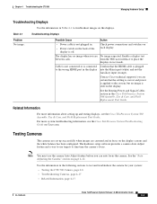
...when you are certain that the HDMI cable is off. from the Web user interface to place the displays in the Cisco TelePresence System 500 Assembly, Use & Care, and Field Replacement Unit Guide. Contact Cisco technical support if you are centered and in the display into the Main ... in focus on the displays. For more information about setting up successfully when images are No image expected. Chapter 4 Troubleshooting the CTS 500 Managing Hardware Setup Troubleshooting Displays Use the information in the following sections to test and troubleshoot the camera for your system: &#...
...when you are certain that the HDMI cable is off. from the Web user interface to place the displays in the Cisco TelePresence System 500 Assembly, Use & Care, and Field Replacement Unit Guide. Contact Cisco technical support if you are centered and in the display into the Main ... in focus on the displays. For more information about setting up successfully when images are No image expected. Chapter 4 Troubleshooting the CTS 500 Managing Hardware Setup Troubleshooting Displays Use the information in the following sections to test and troubleshoot the camera for your system: &#...

Administration Guide
Page 78
Step 2 Pull the bottom of the hood until the entire unit snaps off until that the user will occupy. Click Start. Cisco TelePresence System Release 1.6 Administration Guide 4-6 OL-13676-05 It should be removed and left off of the hood snaps open. Set the easel and large target.... The display enters loopback mode. The entire camera hood and speaker cover attachment comes off . Setting up the Camera Targets To set up the CTS 500 camera for testing: • Removing the Camera Hood, page 4-6 • Setting up the camera target, follow these steps. In loopback ...
Step 2 Pull the bottom of the hood until the entire unit snaps off until that the user will occupy. Click Start. Cisco TelePresence System Release 1.6 Administration Guide 4-6 OL-13676-05 It should be removed and left off of the hood snaps open. Set the easel and large target.... The display enters loopback mode. The entire camera hood and speaker cover attachment comes off . Setting up the Camera Targets To set up the CTS 500 camera for testing: • Removing the Camera Hood, page 4-6 • Setting up the camera target, follow these steps. In loopback ...

Administration Guide
Page 79
... in Figure 4-2. Use the distance measured from the display for all CTS-500 installations. Figure 4-3 shows a pedestal stand-mounted CTS 500. OL-13676-05 Cisco TelePresence System Release 1.6 Administration Guide 4-7 Chapter 4 Troubleshooting the CTS 500 Managing Hardware Setup Step 5 Click Show Camera Target. Note The user must be at least 4 feet (1.2 meters) away from the camera...
... in Figure 4-2. Use the distance measured from the display for all CTS-500 installations. Figure 4-3 shows a pedestal stand-mounted CTS 500. OL-13676-05 Cisco TelePresence System Release 1.6 Administration Guide 4-7 Chapter 4 Troubleshooting the CTS 500 Managing Hardware Setup Step 5 Click Show Camera Target. Note The user must be at least 4 feet (1.2 meters) away from the camera...

Administration Guide
Page 80
Cisco TelePresence System Release 1.6 Administration Guide 4-8 OL-13676-05 Managing Hardware Setup Figure 4-3 Camera Target Placement Large target 5 ft (1.5 m) Easel Chapter 4 Troubleshooting the CTS 500 Height adjustment knob 205016 Step 8 Raise or lower the CTS 500 so that the green rectangle that displays on the screen is at the approximate eye level of the CTS-500... the following guidelines when raising and lowering the stand (see Figure 4-4 and Figure 4-5): • Do not grasp the light reflector, or any part of the CTS 500 user. Note If you have a wall-mounted...
Cisco TelePresence System Release 1.6 Administration Guide 4-8 OL-13676-05 Managing Hardware Setup Figure 4-3 Camera Target Placement Large target 5 ft (1.5 m) Easel Chapter 4 Troubleshooting the CTS 500 Height adjustment knob 205016 Step 8 Raise or lower the CTS 500 so that the green rectangle that displays on the screen is at the approximate eye level of the CTS-500... the following guidelines when raising and lowering the stand (see Figure 4-4 and Figure 4-5): • Do not grasp the light reflector, or any part of the CTS 500 user. Note If you have a wall-mounted...

Administration Guide
Page 82
Managing Hardware Setup Chapter 4 Troubleshooting the CTS 500 Figure 4-5 Height Adjustment Guidelines-Table Stand-Mounted CTS-500 205651 Note If the user is not available, or if the CTS 500 will be used by multiple people, use them to position the CTS 500. If the user is available, use an average eye level height. 4-10 Cisco TelePresence System Release 1.6 Administration Guide OL-13676-05
Managing Hardware Setup Chapter 4 Troubleshooting the CTS 500 Figure 4-5 Height Adjustment Guidelines-Table Stand-Mounted CTS-500 205651 Note If the user is not available, or if the CTS 500 will be used by multiple people, use them to position the CTS 500. If the user is available, use an average eye level height. 4-10 Cisco TelePresence System Release 1.6 Administration Guide OL-13676-05

Administration Guide
Page 83
... are just touching the left and right borders of correct zoom adjustment. If possible, move the target slightly from the position that the user will occupy. Step 9 Position the easel so the black plus sign (+) of the target is complete. Click Remove Camera Target to ... height. Tighten the thumbscrew when the adjustment is in the Cisco TelePresence System 500 Assembly, Use & Care, and Field Replaceable Unit Guide. Chapter 4 Troubleshooting the CTS 500 Managing Hardware Setup Tip If you have a pedestal stand-mounted CTS 500 and applied the height sticker, you can raise and ...
... are just touching the left and right borders of correct zoom adjustment. If possible, move the target slightly from the position that the user will occupy. Step 9 Position the easel so the black plus sign (+) of the target is complete. Click Remove Camera Target to ... height. Tighten the thumbscrew when the adjustment is in the Cisco TelePresence System 500 Assembly, Use & Care, and Field Replaceable Unit Guide. Chapter 4 Troubleshooting the CTS 500 Managing Hardware Setup Tip If you have a pedestal stand-mounted CTS 500 and applied the height sticker, you can raise and ...

Administration Guide
Page 85
... field. To focus the camera, follow these guidelines: • If the user is 1.2 meters to 1.5 meters (4 to set up the Camera Targets, adjust the camera focus. Focusing the Camera The CTS 500 camera has vertical height, zoom, and focus adjustments. Understanding Camera Setup ...Choices for Room Lighting If your installation. See the "Testing the CTS 500 Camera" section on four sides1 Enable Enable 1. OL-13676-05 Cisco TelePresence System Release 1.6 Administration Guide 4-13 After you change the ballast for desirable display and camera settings when you...
... field. To focus the camera, follow these guidelines: • If the user is 1.2 meters to 1.5 meters (4 to set up the Camera Targets, adjust the camera focus. Focusing the Camera The CTS 500 camera has vertical height, zoom, and focus adjustments. Understanding Camera Setup ...Choices for Room Lighting If your installation. See the "Testing the CTS 500 Camera" section on four sides1 Enable Enable 1. OL-13676-05 Cisco TelePresence System Release 1.6 Administration Guide 4-13 After you change the ballast for desirable display and camera settings when you...

Administration Guide
Page 101
.... Click the Other Devices radio button. Shroud Light Each CTS 500 has a separate shroud light. Click Select All to end the test. LEDs Each CTS 500 has five LEDs located around the outside edges of the...user is displayed. Click the Other Devices radio button. Choose Troubleshooting > Hardware Setup. Click the Reset Auxiliary Control Unit to test the selected light unit(s). This troubleshooting feature lets you view and change the status of the shroud light. Choose Troubleshooting > Hardware Setup. Or b. OL-13676-05 Cisco TelePresence System Release 1.6 Administration Guide...
.... Click the Other Devices radio button. Shroud Light Each CTS 500 has a separate shroud light. Click Select All to end the test. LEDs Each CTS 500 has five LEDs located around the outside edges of the...user is displayed. Click the Other Devices radio button. Choose Troubleshooting > Hardware Setup. Click the Reset Auxiliary Control Unit to test the selected light unit(s). This troubleshooting feature lets you view and change the status of the shroud light. Choose Troubleshooting > Hardware Setup. Or b. OL-13676-05 Cisco TelePresence System Release 1.6 Administration Guide...