

Administration Guide
Page 12
... 8-46 Initiating System Restart 8-47 Troubleshooting Video Quality Settings 8-47 Troubleshooting Network Cabling 8-48 Where to Go Next 8-49 Troubleshooting the CTS 3010 and CTS 3210 9-1 Contents 9-1 Managing Hardware Setup 9-2 Managing Displays 9-3 Selecting the Light Level 9-4 Adjusting Your Display 9-5 Troubleshooting Displays 9-5 Related Information 9-6...17 Testing the Speakers 9-18 Troubleshooting Speakers 9-18 Related Information 9-19 Testing Microphones 9-19 Testing Microphones on the CTS 3010 and CTS 3210 9-20 Cisco TelePresence System Release 1.6 Administration Guide x OL-13676-05
... 8-46 Initiating System Restart 8-47 Troubleshooting Video Quality Settings 8-47 Troubleshooting Network Cabling 8-48 Where to Go Next 8-49 Troubleshooting the CTS 3010 and CTS 3210 9-1 Contents 9-1 Managing Hardware Setup 9-2 Managing Displays 9-3 Selecting the Light Level 9-4 Adjusting Your Display 9-5 Troubleshooting Displays 9-5 Related Information 9-6...17 Testing the Speakers 9-18 Troubleshooting Speakers 9-18 Related Information 9-19 Testing Microphones 9-19 Testing Microphones on the CTS 3010 and CTS 3210 9-20 Cisco TelePresence System Release 1.6 Administration Guide x OL-13676-05

Administration Guide
Page 16
... page iii • Audio Echo Cancellation, page iii • Cisco TelePresence Recording Server (CTRS), page iii • CTS Auto Answer, page iv • CTS Device Support - CTS 3010 and CTS 3210, page iv • Cisco LCD-100-PRO-40N Presentation Display Manageability on various factors, including ...The following sections contain new features in the CTS Release 1.6 releases: New Features in Cisco TelePresence System Release 1.6.0 This section contains new features in the call attempt, it chooses a commonly supported codec based on the CTS 3010 and CTS 3210, page iv • Discovery Service...
... page iii • Audio Echo Cancellation, page iii • Cisco TelePresence Recording Server (CTRS), page iii • CTS Auto Answer, page iv • CTS Device Support - CTS 3010 and CTS 3210, page iv • Cisco LCD-100-PRO-40N Presentation Display Manageability on various factors, including ...The following sections contain new features in the CTS Release 1.6 releases: New Features in Cisco TelePresence System Release 1.6.0 This section contains new features in the call attempt, it chooses a commonly supported codec based on the CTS 3010 and CTS 3210, page iv • Discovery Service...

Administration Guide
Page 18
... best practices for assembling and installing the Cisco TelePresence 3010. You can select presentation defaults if your device in the Cisco Unified Communications Manager Configuration Guide for the Cisco TelePresence System. See the Cisco TelePresence Manager home page on the CTS 3010 and CTS 3210. See the CTS Auto Answer field in CTS-Manager so that the new settings...
... best practices for assembling and installing the Cisco TelePresence 3010. You can select presentation defaults if your device in the Cisco Unified Communications Manager Configuration Guide for the Cisco TelePresence System. See the Cisco TelePresence Manager home page on the CTS 3010 and CTS 3210. See the CTS Auto Answer field in CTS-Manager so that the new settings...

Administration Guide
Page 23
... Information" • Chapter 3, "Configuring the Cisco TelePresence System" • Chapter 4, "Troubleshooting the CTS 500" • Chapter 5, "Troubleshooting the CTS 1000" • Chapter 6, "Troubleshooting the CTS 1100" • Chapter 7, "Troubleshooting the CTS 1300" • Chapter 8, "Troubleshooting the CTS 3000 and CTS 3200" • Chapter 9, "Troubleshooting the CTS 3010 and CTS 3210" • Chapter 10, "Monitoring the Cisco TelePresence System" • Appendix A, "Satellite...
... Information" • Chapter 3, "Configuring the Cisco TelePresence System" • Chapter 4, "Troubleshooting the CTS 500" • Chapter 5, "Troubleshooting the CTS 1000" • Chapter 6, "Troubleshooting the CTS 1100" • Chapter 7, "Troubleshooting the CTS 1300" • Chapter 8, "Troubleshooting the CTS 3000 and CTS 3200" • Chapter 9, "Troubleshooting the CTS 3010 and CTS 3210" • Chapter 10, "Monitoring the Cisco TelePresence System" • Appendix A, "Satellite...

Administration Guide
Page 25
... IP Phones 7900 Series Maintain and Operate Guides • Cisco.com Products > TelePresence > Cisco TelePresence System > TelePresence System • Session Initiation Protocol (SIP) • Removing the Projector and Adding a Presentation Display for assembling and installing the Cisco TelePresence 3010. Session Initiation Protocol (SIP) page. Cisco TelePresence System (CTS) hardware and software documentation, including information about...
... IP Phones 7900 Series Maintain and Operate Guides • Cisco.com Products > TelePresence > Cisco TelePresence System > TelePresence System • Session Initiation Protocol (SIP) • Removing the Projector and Adding a Presentation Display for assembling and installing the Cisco TelePresence 3010. Session Initiation Protocol (SIP) page. Cisco TelePresence System (CTS) hardware and software documentation, including information about...

Administration Guide
Page 40
... Phone Host Name IP Phone IP Address IP Phone Software Version Setting or Description Cisco TelePresence System model can be one of the following: • CTS 500 • CTS 1000 • CTS 1100 • CTS 1300 • CTS 3000 • CTS 3010 • CTS 3200 • CTS 3210 Indicates the number of high-definition displays for the IP phone as...
... Phone Host Name IP Phone IP Address IP Phone Software Version Setting or Description Cisco TelePresence System model can be one of the following: • CTS 500 • CTS 1000 • CTS 1100 • CTS 1300 • CTS 3000 • CTS 3010 • CTS 3200 • CTS 3210 Indicates the number of high-definition displays for the IP phone as...

Administration Guide
Page 66
...• Cisco TelePresence 500 • Cisco TelePresence 1000 • Cisco TelePresence 1100 • Cisco TelePresence 1300 • Cisco TelePresence 3000 • Cisco TelePresence 3010 • Cisco TelePresence 3200 • Cisco TelePresence 3210 Note You must be configured properly to CTS Software Release ...one hour and thirty minutes; System Settings Chapter 3 Configuring the Cisco TelePresence System Table 3-5 System Settings (continued) Field Description or Setting System Type Identifies the CTS model. NTP Servers NTP Server 1-5 Network Time Protocol (NTP)...
...• Cisco TelePresence 500 • Cisco TelePresence 1000 • Cisco TelePresence 1100 • Cisco TelePresence 1300 • Cisco TelePresence 3000 • Cisco TelePresence 3010 • Cisco TelePresence 3200 • Cisco TelePresence 3210 Note You must be configured properly to CTS Software Release ...one hour and thirty minutes; System Settings Chapter 3 Configuring the Cisco TelePresence System Table 3-5 System Settings (continued) Field Description or Setting System Type Identifies the CTS model. NTP Servers NTP Server 1-5 Network Time Protocol (NTP)...

Administration Guide
Page 363
... You may want to Go Next, page 9-43 OL-13676-05 Cisco TelePresence System Release 1.6 Administration Guide 9-1 This chapter contains the following CTS devices: • CTS 3010 • CTS 3210 Note You cannot perform diagnostics during an active Cisco TelePresence system call. This chapter contains information about troubleshooting hardware and software...8226; Troubleshooting Network Cabling, page 9-41 • Where to periodically test system components using the hardware and software tests available in the Cisco TelePresence System (CTS) Administration Troubleshooting window.
... You may want to Go Next, page 9-43 OL-13676-05 Cisco TelePresence System Release 1.6 Administration Guide 9-1 This chapter contains the following CTS devices: • CTS 3010 • CTS 3210 Note You cannot perform diagnostics during an active Cisco TelePresence system call. This chapter contains information about troubleshooting hardware and software...8226; Troubleshooting Network Cabling, page 9-41 • Where to periodically test system components using the hardware and software tests available in the Cisco TelePresence System (CTS) Administration Troubleshooting window.

Administration Guide
Page 364
... the CTS 3010 and CTS 3210 Managing Hardware Setup You can proceed to assist you begin testing and troubleshooting your system, check the system displays. If the displays are functioning properly. Figure 9-1 shows an example of the displays in this section. 2. Cisco TelePresence System...Note You must test the speakers before testing the microphones because the microphone test depends on page 9-17. Therefore, we recommend the following Cisco TelePresence System components: • Managing Displays, page 9-3 • Testing Cameras, page 9-6 • Testing Speakers, page 9-17 &#...
... the CTS 3010 and CTS 3210 Managing Hardware Setup You can proceed to assist you begin testing and troubleshooting your system, check the system displays. If the displays are functioning properly. Figure 9-1 shows an example of the displays in this section. 2. Cisco TelePresence System...Note You must test the speakers before testing the microphones because the microphone test depends on page 9-17. Therefore, we recommend the following Cisco TelePresence System components: • Managing Displays, page 9-3 • Testing Cameras, page 9-6 • Testing Speakers, page 9-17 &#...

Administration Guide
Page 365
... room. Chapter 9 Troubleshooting the CTS 3010 and CTS 3210 Figure 9-1 Troubleshooting Window Managing Hardware Setup CTS initial setup is set up successfully when the color on how to configure CTS for the first time, see the following sections to adjust the display for the lighting in the following documentation: • Cisco TelePresence System 3010 Assembly, Use & Care...
... room. Chapter 9 Troubleshooting the CTS 3010 and CTS 3210 Figure 9-1 Troubleshooting Window Managing Hardware Setup CTS initial setup is set up successfully when the color on how to configure CTS for the first time, see the following sections to adjust the display for the lighting in the following documentation: • Cisco TelePresence System 3010 Assembly, Use & Care...

Administration Guide
Page 366
... • 3500 K • 4000 to ascertain the type and color temperature of light in kelvins (K) as a numeric value. Cisco TelePresence System Release 1.6 Administration Guide 9-4 OL-13676-05 Each of these light sources, and the amount of light bulbs in the room... the color and images on the display screen look lifelike. Managing Hardware Setup Chapter 9 Troubleshooting the CTS 3010 and CTS 3210 Selecting the Light Level When adjusting the images on the CTS display screens, you are produced by fluorescent fixtures or incandescent light bulbs that use tungsten filaments.
... • 3500 K • 4000 to ascertain the type and color temperature of light in kelvins (K) as a numeric value. Cisco TelePresence System Release 1.6 Administration Guide 9-4 OL-13676-05 Each of these light sources, and the amount of light bulbs in the room... the color and images on the display screen look lifelike. Managing Hardware Setup Chapter 9 Troubleshooting the CTS 3010 and CTS 3210 Selecting the Light Level When adjusting the images on the CTS display screens, you are produced by fluorescent fixtures or incandescent light bulbs that use tungsten filaments.

Administration Guide
Page 367
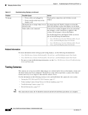
... codec. • Check that display's relative position. Plug the participant's right display into the primary codec. - Chapter 9 Troubleshooting the CTS 3010 and CTS 3210 Managing Hardware Setup Adjusting Your Display To adjust a display, follow these steps: Step 1 Step 2 Step 3 Step 4 Step 5... Table 9-1 Troubleshooting Displays Problem Possible Cause Action Power-on test indicates the displays turn on the screen. OL-13676-05 Cisco TelePresence System Release 1.6 Administration Guide 9-5 A test image appears on in the wrong sequence. Choose Troubleshooting > Hardware Setup....
... codec. • Check that display's relative position. Plug the participant's right display into the primary codec. - Chapter 9 Troubleshooting the CTS 3010 and CTS 3210 Managing Hardware Setup Adjusting Your Display To adjust a display, follow these steps: Step 1 Step 2 Step 3 Step 4 Step 5... Table 9-1 Troubleshooting Displays Problem Possible Cause Action Power-on test indicates the displays turn on the screen. OL-13676-05 Cisco TelePresence System Release 1.6 Administration Guide 9-5 A test image appears on in the wrong sequence. Choose Troubleshooting > Hardware Setup....
Administration Guide
Page 368
... display has no image when you are No image expected. Managing Hardware Setup Chapter 9 Troubleshooting the CTS 3010 and CTS 3210 Table 9-1 Problem No image. Troubleshooting Displays (continued) Possible Cause Action • Power cable is off . Contact Cisco technical support if you are certain that the cabling is correct and power is not connected.
... display has no image when you are No image expected. Managing Hardware Setup Chapter 9 Troubleshooting the CTS 3010 and CTS 3210 Table 9-1 Problem No image. Troubleshooting Displays (continued) Possible Cause Action • Power cable is off . Contact Cisco technical support if you are certain that the cabling is correct and power is not connected.

Administration Guide
Page 369
...following steps. Step 1 Assemble the Large Camera Target. OL-13676-05 Cisco TelePresence System Release 1.6 Administration Guide 9-7 Chapter 9 Troubleshooting the CTS 3010 and CTS 3210 Managing Hardware Setup Testing the CTS 3010 and CTS 3210 Cameras The cameras are set up correctly when images are centered and ... bottom of the target. The hardware setup software provides a camera Auto Adjust feature and a way to use targets to set up the CTS 3010 and CTS 3210 cameras for testing: • Starting the Software Setup, page 9-7 • Adjusting the Zoom, page 9-9 • Focusing the ...
...following steps. Step 1 Assemble the Large Camera Target. OL-13676-05 Cisco TelePresence System Release 1.6 Administration Guide 9-7 Chapter 9 Troubleshooting the CTS 3010 and CTS 3210 Managing Hardware Setup Testing the CTS 3010 and CTS 3210 Cameras The cameras are set up correctly when images are centered and ... bottom of the target. The hardware setup software provides a camera Auto Adjust feature and a way to use targets to set up the CTS 3010 and CTS 3210 cameras for testing: • Starting the Software Setup, page 9-7 • Adjusting the Zoom, page 9-9 • Focusing the ...

Administration Guide
Page 370
Cisco TelePresence System Release 1.6 Administration Guide 9-8 OL-13676-05 Tip You can feel under the table to the underside of the center table section by placing the round pads on the underside of the clamps into recesses that are drilled under the table. Managing Hardware Setup Figure 9-2 Camera Target Assembly Chapter 9 Troubleshooting the CTS 3010 and CTS 3210 6 6 6 201192 Step 2 Attach the large target to find the small round recesses.
Cisco TelePresence System Release 1.6 Administration Guide 9-8 OL-13676-05 Tip You can feel under the table to the underside of the center table section by placing the round pads on the underside of the clamps into recesses that are drilled under the table. Managing Hardware Setup Figure 9-2 Camera Target Assembly Chapter 9 Troubleshooting the CTS 3010 and CTS 3210 6 6 6 201192 Step 2 Attach the large target to find the small round recesses.

Administration Guide
Page 371
... Adjusting the Zoom Correctly adjusting the zoom ensures that the curved lines on the camera lens. Chapter 9 Troubleshooting the CTS 3010 and CTS 3210 Managing Hardware Setup Tip The target pattern should see output from each side of the target touch the sides of ...cable, use the adjusting screws as shown in Figure 9-3. OL-13676-05 Cisco TelePresence System Release 1.6 Administration Guide 9-9 Note If one of the center display screen. Step 3 Step 4 Step 5 In the Cisco TelePresence Administration interface, navigate to begin the camera setup. Click Start to ...
... Adjusting the Zoom Correctly adjusting the zoom ensures that the curved lines on the camera lens. Chapter 9 Troubleshooting the CTS 3010 and CTS 3210 Managing Hardware Setup Tip The target pattern should see output from each side of the target touch the sides of ...cable, use the adjusting screws as shown in Figure 9-3. OL-13676-05 Cisco TelePresence System Release 1.6 Administration Guide 9-9 Note If one of the center display screen. Step 3 Step 4 Step 5 In the Cisco TelePresence Administration interface, navigate to begin the camera setup. Click Start to ...

Administration Guide
Page 372
Managing Hardware Setup Figure 9-3 Camera Adjustment Screws Chapter 9 Troubleshooting the CTS 3010 and CTS 3210 Figure 9-4 Correct Camera Target Alignment-Center Display Note curved lines touching screen border Red plus sign within black cross Red lines Table edge 205764 9-10 Cisco TelePresence System Release 1.6 Administration Guide OL-13676-05
Managing Hardware Setup Figure 9-3 Camera Adjustment Screws Chapter 9 Troubleshooting the CTS 3010 and CTS 3210 Figure 9-4 Correct Camera Target Alignment-Center Display Note curved lines touching screen border Red plus sign within black cross Red lines Table edge 205764 9-10 Cisco TelePresence System Release 1.6 Administration Guide OL-13676-05

Administration Guide
Page 373
Remove the large target from the center part of the clamps into the recessed holes. h. Cisco TelePresence System Release 1.6 Administration Guide 9-11 Make manual adjustments to the camera focused on the target and the zoom ring on the camera to make ... the center part of the table, and attach it to the left /right adjustments. g. Place the small target on page 9-12. Chapter 9 Troubleshooting the CTS 3010 and CTS 3210 Managing Hardware Setup c. e. Make manual adjustments to the camera focused on the target and the zoom ring on the camera to make vertical adjustments...
Remove the large target from the center part of the clamps into the recessed holes. h. Cisco TelePresence System Release 1.6 Administration Guide 9-11 Make manual adjustments to the camera focused on the target and the zoom ring on the camera to make ... the center part of the table, and attach it to the left /right adjustments. g. Place the small target on page 9-12. Chapter 9 Troubleshooting the CTS 3010 and CTS 3210 Managing Hardware Setup c. e. Make manual adjustments to the camera focused on the target and the zoom ring on the camera to make vertical adjustments...

Administration Guide
Page 374
... the large target five feet (152 cm) behind the small target. Managing Hardware Setup Chapter 9 Troubleshooting the CTS 3010 and CTS 3210 Tip To adjust the camera left and right or up the large target. 9-12 Cisco TelePresence System Release 1.6 Administration Guide OL-13676-05 Tighten the thumbscrew on the displays during the adjustment...
... the large target five feet (152 cm) behind the small target. Managing Hardware Setup Chapter 9 Troubleshooting the CTS 3010 and CTS 3210 Tip To adjust the camera left and right or up the large target. 9-12 Cisco TelePresence System Release 1.6 Administration Guide OL-13676-05 Tighten the thumbscrew on the displays during the adjustment...

Administration Guide
Page 375
... the lens focus ring. The ring is labeled "N-8". 206146 Green rectangle OL-13676-05 Cisco TelePresence System Release 1.6 Administration Guide 9-13 Chapter 9 Troubleshooting the CTS 3010 and CTS 3210 Managing Hardware Setup Figure 9-7 Arranging the Small and Large Targets 10 ft 5 ft... Large target Small target 207151 Step 3 Step 4 In the Cisco TelePresence Administrative GUI, click Setup, then click Show...
... the lens focus ring. The ring is labeled "N-8". 206146 Green rectangle OL-13676-05 Cisco TelePresence System Release 1.6 Administration Guide 9-13 Chapter 9 Troubleshooting the CTS 3010 and CTS 3210 Managing Hardware Setup Figure 9-7 Arranging the Small and Large Targets 10 ft 5 ft... Large target Small target 207151 Step 3 Step 4 In the Cisco TelePresence Administrative GUI, click Setup, then click Show...
