Administration Guide
Page 49
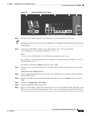
... Cisco TelePresence system provided for your session. OL-21845-01 Cisco TelePresence System Administration Guide 3-5 Chapter 3 Configuring the Cisco TelePresence System Figure 3-3 Auxiliary Network Port Location First Time Setup for All Other CTS Models Step 2 Determine the IP address that the Cisco Telepresence system provided an IP address of 10.1.0.2, enter the address 10.1.0.1. By default, the username is admin and the password is cisco. Change the DHCP Enabled setting to Configuration > IP Settings. Your system saves the changes...
... Cisco TelePresence system provided for your session. OL-21845-01 Cisco TelePresence System Administration Guide 3-5 Chapter 3 Configuring the Cisco TelePresence System Figure 3-3 Auxiliary Network Port Location First Time Setup for All Other CTS Models Step 2 Determine the IP address that the Cisco Telepresence system provided an IP address of 10.1.0.2, enter the address 10.1.0.1. By default, the username is admin and the password is cisco. Change the DHCP Enabled setting to Configuration > IP Settings. Your system saves the changes...
Administration Guide
Page 78
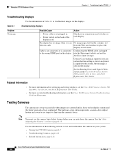
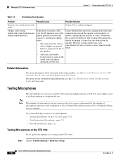
... balance has been configured. Note You must use targets to test and troubleshoot the camera for your system: • Testing the CTS 500 Camera, page 4-7 • Troubleshooting Cameras, page 4-21 • Related Information, page 4-21 Cisco TelePresence System Administration Guide 4-6 OL-21845-01 Table 4-1 Troubleshooting Displays Problem No image. The display has no image is off. Managing CTS 500 Hardware Setup Chapter 4 Troubleshooting the CTS 500 Troubleshooting Displays Use...
... balance has been configured. Note You must use targets to test and troubleshoot the camera for your system: • Testing the CTS 500 Camera, page 4-7 • Troubleshooting Cameras, page 4-21 • Related Information, page 4-21 Cisco TelePresence System Administration Guide 4-6 OL-21845-01 Table 4-1 Troubleshooting Displays Problem No image. The display has no image is off. Managing CTS 500 Hardware Setup Chapter 4 Troubleshooting the CTS 500 Troubleshooting Displays Use...
Administration Guide
Page 93
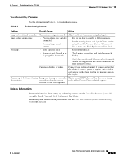
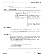
.... • Video cable is only partially connected. • Color settings are certain that the video and Ethernet cables from each is seen on Cisco.com. For more information about setting up to 1 second to see the Cisco TelePresence System Troubleshooting Guide on the display. Adjust and focus the camera using the targets. Camera is broken. Chapter 4 Troubleshooting the CTS 500 Managing CTS 500 Hardware Setup Troubleshooting Cameras Use the...
.... • Video cable is only partially connected. • Color settings are certain that the video and Ethernet cables from each is seen on Cisco.com. For more information about setting up to 1 second to see the Cisco TelePresence System Troubleshooting Guide on the display. Adjust and focus the camera using the targets. Camera is broken. Chapter 4 Troubleshooting the CTS 500 Managing CTS 500 Hardware Setup Troubleshooting Cameras Use the...
Administration Guide
Page 95
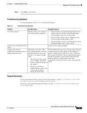
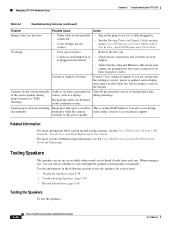
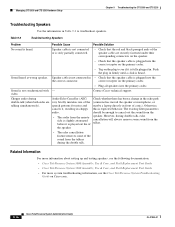
...Troubleshooting the CTS 500 Managing CTS 500 Hardware Setup Step 8 Click Stop to troubleshoot speakers. Table 4-4 Troubleshooting Speakers Problem...some sound from the remote side is slightly attenuated before it is only partially connected. • Check that...Cisco TelePresence System Administration Guide 4-23 Check whether there has been a change in the echo path (someone has moved the speaker or microphone, or maybe a laptop directly in Table 4-4 to end testing. For more information about setting up and testing speakers, see the Cisco TelePresence System Troubleshooting Guide...
...Troubleshooting the CTS 500 Managing CTS 500 Hardware Setup Step 8 Click Stop to troubleshoot speakers. Table 4-4 Troubleshooting Speakers Problem...some sound from the remote side is slightly attenuated before it is only partially connected. • Check that...Cisco TelePresence System Administration Guide 4-23 Check whether there has been a change in the echo path (someone has moved the speaker or microphone, or maybe a laptop directly in Table 4-4 to end testing. For more information about setting up and testing speakers, see the Cisco TelePresence System Troubleshooting Guide...

Administration Guide
Page 98
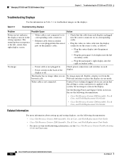
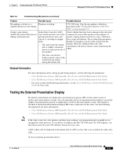
... Field Replacement Unit Guide. For more information about setting up and testing displays, see the Cisco TelePresence System Troubleshooting Guide on Cisco.com. The existing filter parameters should run this is handled by system. Optional in front of a mic). Check whether there has been a change in the echo path (someone has moved the speaker or microphone, or maybe a laptop directly in Cisco TelePresence System • CTS...
... Field Replacement Unit Guide. For more information about setting up and testing displays, see the Cisco TelePresence System Troubleshooting Guide on Cisco.com. The existing filter parameters should run this is handled by system. Optional in front of a mic). Check whether there has been a change in the echo path (someone has moved the speaker or microphone, or maybe a laptop directly in Cisco TelePresence System • CTS...

Administration Guide
Page 136
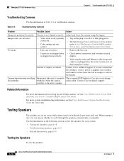
... CTS 1000 Hardware Setup Chapter 6 Troubleshooting the CTS 1000 Troubleshooting Displays Use the information in Table 6-1 to test and troubleshoot the camera for your system: • Testing the CTS 1000 Camera, page 6-7 • Understanding Camera Setup Choices for Room Lighting, page 6-17 • Troubleshooting Cameras, page 6-18 • Related Information, page 6-18 Cisco TelePresence System Administration Guide 6-6 OL-21845-01 from the Web user interface to fine-tune the camera's focus. The hardware setup software provides a camera...
... CTS 1000 Hardware Setup Chapter 6 Troubleshooting the CTS 1000 Troubleshooting Displays Use the information in Table 6-1 to test and troubleshoot the camera for your system: • Testing the CTS 1000 Camera, page 6-7 • Understanding Camera Setup Choices for Room Lighting, page 6-17 • Troubleshooting Cameras, page 6-18 • Related Information, page 6-18 Cisco TelePresence System Administration Guide 6-6 OL-21845-01 from the Web user interface to fine-tune the camera's focus. The hardware setup software provides a camera...
Administration Guide
Page 148
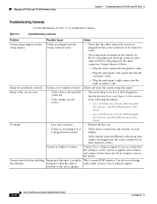
... connectors on the plug to cycle through the speakers automatically or manually. For more information about setting up successfully when sound can choose whether to see the Cisco TelePresence System 1000 Assembly, Use & Care, and Field Replacement Unit Guide. Camera is broken. Camera or display is not aligned correctly. Table 6-3 Troubleshooting Cameras Problem Possible Cause Action Image not positioned correctly. normalize when the...
... connectors on the plug to cycle through the speakers automatically or manually. For more information about setting up successfully when sound can choose whether to see the Cisco TelePresence System 1000 Assembly, Use & Care, and Field Replacement Unit Guide. Camera is broken. Camera or display is not aligned correctly. Table 6-3 Troubleshooting Cameras Problem Possible Cause Action Image not positioned correctly. normalize when the...

Administration Guide
Page 156
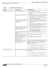
... any objects blocking the projector lens. Table 6-7 Troubleshooting Presentation Devices Problem Test pattern is blocking the path of the Cisco Unified Communications Manager Configuration Guide for the Cisco TelePresence System for HD Video input. • If your system includes an Auxiliary Control Unit, click Set Projector Defaults. System Status window shows unexpected Document Camera status. Video cable is not connected to the projector or to the...
... any objects blocking the projector lens. Table 6-7 Troubleshooting Presentation Devices Problem Test pattern is blocking the path of the Cisco Unified Communications Manager Configuration Guide for the Cisco TelePresence System for HD Video input. • If your system includes an Auxiliary Control Unit, click Set Projector Defaults. System Status window shows unexpected Document Camera status. Video cable is not connected to the projector or to the...
Administration Guide
Page 176
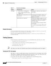
... seen on Cisco.com. The hardware setup software provides a camera Auto Adjust feature and uses targets to test and troubleshoot the camera for your system: • Testing the CTS 1100 Camera, page 7-6 • Understanding Camera Setup Choices for testing, complete the tasks in the following sections: • Removing the Camera Cover and Leveling the Camera Cisco TelePresence System Administrator Guide 7-6 OL-21845-01 Contact Cisco technical support if you...
... seen on Cisco.com. The hardware setup software provides a camera Auto Adjust feature and uses targets to test and troubleshoot the camera for your system: • Testing the CTS 1100 Camera, page 7-6 • Understanding Camera Setup Choices for testing, complete the tasks in the following sections: • Removing the Camera Cover and Leveling the Camera Cisco TelePresence System Administrator Guide 7-6 OL-21845-01 Contact Cisco technical support if you...
Administration Guide
Page 188
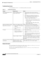
... section in the Cisco TelePresence System 1100 Assembly, Use & Care, and Field Replacement Unit Guide. Related Information For more system troubleshooting information, see if it is plugged in or • Check power connections and switches on each camera are plugged into the large connector and a video-to This is normal DSP behavior. Managing CTS 1100 Hardware Setup Chapter 7 Troubleshooting the CTS 1100 Troubleshooting Cameras Use the...
... section in the Cisco TelePresence System 1100 Assembly, Use & Care, and Field Replacement Unit Guide. Related Information For more system troubleshooting information, see if it is plugged in or • Check power connections and switches on each camera are plugged into the large connector and a video-to This is normal DSP behavior. Managing CTS 1100 Hardware Setup Chapter 7 Troubleshooting the CTS 1100 Troubleshooting Cameras Use the...
Administration Guide
Page 190
... patterns for testing on the CTS 1100: Step 1 Choose Troubleshooting > Hardware Setup. 7-20 Cisco TelePresence System Administrator Guide OL-21845-01 Testing Microphones The microphones are running. Choppy audio during the double talk. For more information about setting up the microphones for noise and cancels it is not synchronized with - Contact Cisco technical support. Check whether there has been a change in the echo path...
... patterns for testing on the CTS 1100: Step 1 Choose Troubleshooting > Hardware Setup. 7-20 Cisco TelePresence System Administrator Guide OL-21845-01 Testing Microphones The microphones are running. Choppy audio during the double talk. For more information about setting up the microphones for noise and cancels it is not synchronized with - Contact Cisco technical support. Check whether there has been a change in the echo path...
Administration Guide
Page 219
... the display is applied to troubleshoot problems with the images on the display screens and the white balance has been configured. The hardware setup software provides a camera Auto Adjust feature and a way to use targets to test and troubleshoot the camera for your system: • Testing the CTS 1300 Cameras, page 8-8 • Configuring the CTS 1300 for Use With a Conference Room Table, page 8-12...
... the display is applied to troubleshoot problems with the images on the display screens and the white balance has been configured. The hardware setup software provides a camera Auto Adjust feature and a way to use targets to test and troubleshoot the camera for your system: • Testing the CTS 1300 Cameras, page 8-8 • Configuring the CTS 1300 for Use With a Conference Room Table, page 8-12...
Administration Guide
Page 260
.... • See the Routing Power and Signal Cables section in the Cisco TelePresence System 1300 Assembly, Use & Care, and Field Replacement Unit Guide. Managing CTS 1300 Hardware Setup Chapter 8 Troubleshooting the CTS 1300 Table 8-3 Troubleshooting Cameras (continued) Problem Possible Cause Action Image colors are incorrect. • Video cable is only partially connected. • Color settings are not correct. • Tug on each is plugged in...
.... • See the Routing Power and Signal Cables section in the Cisco TelePresence System 1300 Assembly, Use & Care, and Field Replacement Unit Guide. Managing CTS 1300 Hardware Setup Chapter 8 Troubleshooting the CTS 1300 Table 8-3 Troubleshooting Cameras (continued) Problem Possible Cause Action Image colors are incorrect. • Video cable is only partially connected. • Color settings are not correct. • Tug on each is plugged in...
Administration Guide
Page 290
... For more information about setting up and testing displays, see the following documentation: • Cisco TelePresence System 3000 Assembly, Use & Care, and Field Replacement Unit Guide • Cisco TelePresence System 3200 Assembly, Use & Care, and Field Replacement Unit Guide • For more system troubleshooting information, see the Cisco TelePresence System Troubleshooting Guide on Cisco.com. Managing CTS 3000 and CTS 3200 Hardware Setup Chapter 9 Troubleshooting the CTS 3000 and CTS 3200 Troubleshooting Displays Use the information...
... For more information about setting up and testing displays, see the following documentation: • Cisco TelePresence System 3000 Assembly, Use & Care, and Field Replacement Unit Guide • Cisco TelePresence System 3200 Assembly, Use & Care, and Field Replacement Unit Guide • For more system troubleshooting information, see the Cisco TelePresence System Troubleshooting Guide on Cisco.com. Managing CTS 3000 and CTS 3200 Hardware Setup Chapter 9 Troubleshooting the CTS 3000 and CTS 3200 Troubleshooting Displays Use the information...
Administration Guide
Page 298
.... Plug the participant's left camera into the small connector. Image colors are incorrect. • Video cable is only partially connected. • Color settings are plugged into the correct connectors on the wrong display. normalize when the camera audio addin. Cisco TelePresence System 3000 Assembly, Use & Care, and Field Replacement Unit Guide - Table 9-2 Troubleshooting Cameras Problem Possible Cause Action Camera image appears on their respective...
.... Plug the participant's left camera into the small connector. Image colors are incorrect. • Video cable is only partially connected. • Color settings are plugged into the correct connectors on the wrong display. normalize when the camera audio addin. Cisco TelePresence System 3000 Assembly, Use & Care, and Field Replacement Unit Guide - Table 9-2 Troubleshooting Cameras Problem Possible Cause Action Camera image appears on their respective...
Administration Guide
Page 300
... the speaker cable are talking simultaneously). Related Information For more information about setting up and testing speakers, see the following documentation: • Cisco TelePresence System 3000 Assembly, Use & Care, and Field Replacement Unit Guide • Cisco TelePresence System 3200 Assembly, Use & Care, and Field Replacement Unit Guide • For more system troubleshooting information, see if it , resulting in Table 9-3 to cancel out the...
... the speaker cable are talking simultaneously). Related Information For more information about setting up and testing speakers, see the following documentation: • Cisco TelePresence System 3000 Assembly, Use & Care, and Field Replacement Unit Guide • Cisco TelePresence System 3200 Assembly, Use & Care, and Field Replacement Unit Guide • For more system troubleshooting information, see if it , resulting in Table 9-3 to cancel out the...
Administration Guide
Page 305
... choppy audio. • The audio from the remote side is slightly attenuated before it , resulting in -picture (PiP) on the center screen of multi-screen main display systems. You can optionally add an external presentation display screen that the CTS 3000 and CTS 3200 supports, see the Cisco TelePresence System Troubleshooting Guide on Cisco.com. Choppy audio during double-talk, echo...
... choppy audio. • The audio from the remote side is slightly attenuated before it , resulting in -picture (PiP) on the center screen of multi-screen main display systems. You can optionally add an external presentation display screen that the CTS 3000 and CTS 3200 supports, see the Cisco TelePresence System Troubleshooting Guide on Cisco.com. Choppy audio during double-talk, echo...
Administration Guide
Page 318
... Setting Up the Camera section in the following documentation: • Cisco TelePresence System 3000 Assembly, Use & Care, and Field Replacement Unit Guide • Cisco TelePresence System 3200 Assembly, Use & Care, and Field Replacement Unit Guide 9-34 Cisco TelePresence System Administration Guide OL-21845-01 Power cable is displayed. Seat the HD Video connector securely. Managing CTS 3000 and CTS 3200 Hardware Setup Chapter 9 Troubleshooting the CTS 3000 and CTS 3200 Table 9-6 Troubleshooting Presentation Devices Problem...
... Setting Up the Camera section in the following documentation: • Cisco TelePresence System 3000 Assembly, Use & Care, and Field Replacement Unit Guide • Cisco TelePresence System 3200 Assembly, Use & Care, and Field Replacement Unit Guide 9-34 Cisco TelePresence System Administration Guide OL-21845-01 Power cable is displayed. Seat the HD Video connector securely. Managing CTS 3000 and CTS 3200 Hardware Setup Chapter 9 Troubleshooting the CTS 3000 and CTS 3200 Table 9-6 Troubleshooting Presentation Devices Problem...

Administration Guide
Page 340
...-6 Cisco TelePresence System Administration Guide OL-21845-01 Table 10-1 Troubleshooting Displays Problem Possible Cause Action Power-on test indicates the displays turn on each display is not connected. The display has no image is seen on the back of the display is not plugged in. • Power switch on the display. Web user interface to stop the test. Video...
...-6 Cisco TelePresence System Administration Guide OL-21845-01 Table 10-1 Troubleshooting Displays Problem Possible Cause Action Power-on test indicates the displays turn on each display is not connected. The display has no image is seen on the back of the display is not plugged in. • Power switch on the display. Web user interface to stop the test. Video...

Administration Guide
Page 350
... is in the following documentation: 10-16 Cisco TelePresence System Administration Guide OL-21845-01 Camera or display is not plugged in Table 10-2 to see the following documents: - Managing CTS 3010 and CTS 3210 Hardware Setup Chapter 10 Troubleshooting the CTS 3010 and CTS 3210 Troubleshooting Cameras Use the information in or • Check power connections and switches on the display. display. •...
... is in the following documentation: 10-16 Cisco TelePresence System Administration Guide OL-21845-01 Camera or display is not plugged in Table 10-2 to see the following documents: - Managing CTS 3010 and CTS 3210 Hardware Setup Chapter 10 Troubleshooting the CTS 3010 and CTS 3210 Troubleshooting Cameras Use the information in or • Check power connections and switches on the display. display. •...