Quick Start Guide
Page 1
Quick Start Guide Cisco IP Phone 7914 Expansion Module 1 Introduction to the Cisco IP Phone 7914 Expansion Module 2 Installing the 7914 Expansion Module 3 Features 4 How to Use the 7914 Expansion Module 5 Troubleshooting 6 Technical Specifications 7 For More Information 8 Obtaining Technical Assistance
Quick Start Guide Cisco IP Phone 7914 Expansion Module 1 Introduction to the Cisco IP Phone 7914 Expansion Module 2 Installing the 7914 Expansion Module 3 Features 4 How to Use the 7914 Expansion Module 5 Troubleshooting 6 Technical Specifications 7 For More Information 8 Obtaining Technical Assistance
Quick Start Guide
Page 2
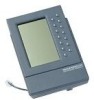
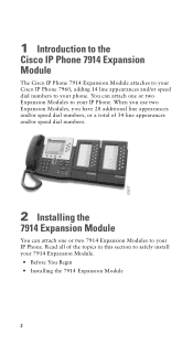
... speed dial numbers. 2 Installing the 7914 Expansion Module You can attach one or two 7914 Expansion Modules to safely install your 7914 Expansion Module. • Before You Begin • Installing the 7914 Expansion Module 2 1 Introduction to the Cisco IP Phone 7914 Expansion Module The Cisco IP Phone 7914 Expansion Module attaches to your Cisco IP Phone 7960, adding 14 line appearances and/or speed dial numbers to your IP Phone. When you use two Expansion Modules, you have 28 additional line...
... speed dial numbers. 2 Installing the 7914 Expansion Module You can attach one or two 7914 Expansion Modules to safely install your 7914 Expansion Module. • Before You Begin • Installing the 7914 Expansion Module 2 1 Introduction to the Cisco IP Phone 7914 Expansion Module The Cisco IP Phone 7914 Expansion Module attaches to your Cisco IP Phone 7960, adding 14 line appearances and/or speed dial numbers to your IP Phone. When you use two Expansion Modules, you have 28 additional line...
Quick Start Guide
Page 3
... The Footstand Kit contains: • One support bar (single with one 7914 Expansion Module, you need a Footstand Kit (separate orderable item). Before You Begin Before you begin installing your 7914 Expansion Module, read all of the following parts in your package: • One Cisco IP Phone 7914 Expansion Module • One RS 232 cable • One Quick Start Guide •... • Additional Equipment • Safety Notices Package List Make sure that you have the double Footstand Kit. If you are attaching two 7914 Expansion Modules, you need to have the single Footstand Kit.
... The Footstand Kit contains: • One support bar (single with one 7914 Expansion Module, you need a Footstand Kit (separate orderable item). Before You Begin Before you begin installing your 7914 Expansion Module, read all of the following parts in your package: • One Cisco IP Phone 7914 Expansion Module • One RS 232 cable • One Quick Start Guide •... • Additional Equipment • Safety Notices Package List Make sure that you have the double Footstand Kit. If you are attaching two 7914 Expansion Modules, you need to have the single Footstand Kit.
Quick Start Guide
Page 4
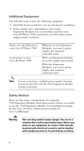
... (separate orderable item). Additional Equipment You will also need to your Cisco IP Phone 7960 is powered, you will void the 7914 Expansion Module product warranty. With one or two Expansion Modules, you work and will require power supply unit(s) as follows: Power over the Ethernet to your Cisco IP Phone 7960 Local power to have the following equipment. • Small...
... (separate orderable item). Additional Equipment You will also need to your Cisco IP Phone 7960 is powered, you will void the 7914 Expansion Module product warranty. With one or two Expansion Modules, you work and will require power supply unit(s) as follows: Power over the Ethernet to your Cisco IP Phone 7960 Local power to have the following equipment. • Small...
Quick Start Guide
Page 6
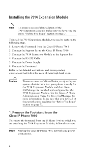
.... Make sure that follow these high-level steps. Remove the Footstand from the Cisco IP Phone 7960 To remove the footstand from the Cisco IP Phone 7960 2. Connect the Support Bar to the Support Bar 4. Installing the 7914 Expansion Module Note To ensure a successful installation of the 7914 Expansion Module, make sure you have all of these steps. Connect the Power Supply...
.... Make sure that follow these high-level steps. Remove the Footstand from the Cisco IP Phone 7960 To remove the footstand from the Cisco IP Phone 7960 2. Connect the Support Bar to the Support Bar 4. Installing the 7914 Expansion Module Note To ensure a successful installation of the 7914 Expansion Module, make sure you have all of these steps. Connect the Power Supply...
Quick Start Guide
Page 7
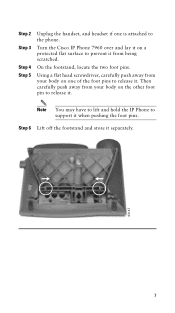
Then carefully push away from being scratched. Note You may have to lift and hold the IP Phone to support it . Step 2 Step 3 Step 4 Step 5 Unplug the handset, and headset if one of the foot pins to release it separately. 63147 7 Using a flat ... a protected flat surface to prevent it from your body on the other foot pin to the phone. On the footstand, locate the two foot pins. Step 6 Lift off the footstand and store it . Turn the Cisco IP Phone 7960 over and lay it on one is attached to release it when pushing the foot...
Then carefully push away from being scratched. Note You may have to lift and hold the IP Phone to support it . Step 2 Step 3 Step 4 Step 5 Unplug the handset, and headset if one of the foot pins to release it separately. 63147 7 Using a flat ... a protected flat surface to prevent it from your body on the other foot pin to the phone. On the footstand, locate the two foot pins. Step 6 Lift off the footstand and store it . Turn the Cisco IP Phone 7960 over and lay it on one is attached to release it when pushing the foot...
Quick Start Guide
Page 8
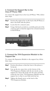
... that the support bar is facing up the two open slots on the support bar. Connect the 7914 Expansion Module to the Support Bar To connect the Expansion Module to the Cisco IP Phone 7960, follow these steps. Step 1 Step 2 Step 3 Position the support bar on the back of the connector pins so that it rests flush with...
... that the support bar is facing up the two open slots on the support bar. Connect the 7914 Expansion Module to the Support Bar To connect the Expansion Module to the Cisco IP Phone 7960, follow these steps. Step 1 Step 2 Step 3 Position the support bar on the back of the connector pins so that it rests flush with...
Quick Start Guide
Page 10
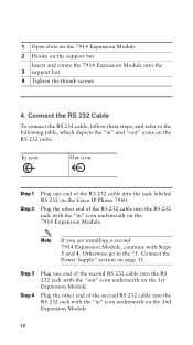
... "out" icons on the 2nd Expansion Module. 10 Connect the RS 232 Cable To connect the RS 232 cable, follow these steps, and refer to the "5. Plug the other end of the RS 232 cable into the RS 232 jack with the "out" icon underneath on the Cisco IP Phone 7960. Step 3 Step 4 Plug... one end of the second RS 232 cable into the RS 232 jack with Steps 3 and 4. Connect the Power Supply" section on the support bar Insert and rotate the 7914 Expansion Module into the jack labeled RS 232 on the 1st...
... "out" icons on the 2nd Expansion Module. 10 Connect the RS 232 Cable To connect the RS 232 cable, follow these steps, and refer to the "5. Plug the other end of the RS 232 cable into the RS 232 jack with the "out" icon underneath on the Cisco IP Phone 7960. Step 3 Step 4 Plug... one end of the second RS 232 cable into the RS 232 jack with Steps 3 and 4. Connect the Power Supply" section on the support bar Insert and rotate the 7914 Expansion Module into the jack labeled RS 232 on the 1st...
Quick Start Guide
Page 11
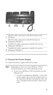
...the RS 232 jack on the 1 IP Phone RS 232 cable connection to the RS 232 jack on 2 Expansion Module 1 2nd RS 232 cable connection to the RS 232 jack on 3 Expansion Module 1 2nd RS 232 cable connection to the AC adaptor port on the Expansion Module and plug the other end into a... outlet in the wall. 11 Step 1 Depending on 4 Expansion Module 2 5. Connect the Power Supply To connect the power supply, follow these steps. you have one Expansion Module-connect the power supply unit to the RS 232 jack on how your Cisco IP Phone 7960 is powered, perform one of the following actions: •...
...the RS 232 jack on the 1 IP Phone RS 232 cable connection to the RS 232 jack on 2 Expansion Module 1 2nd RS 232 cable connection to the RS 232 jack on 3 Expansion Module 1 2nd RS 232 cable connection to the AC adaptor port on the Expansion Module and plug the other end into a... outlet in the wall. 11 Step 1 Depending on 4 Expansion Module 2 5. Connect the Power Supply To connect the power supply, follow these steps. you have one Expansion Module-connect the power supply unit to the RS 232 jack on how your Cisco IP Phone 7960 is powered, perform one of the following actions: •...
Quick Start Guide
Page 12
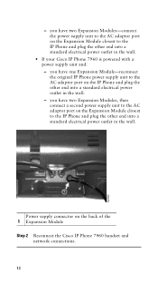
...wall. • If your Cisco IP Phone 7960 is powered with a power supply unit and: - you have two Expansion Modules-connect the power supply unit to the AC adaptor port on the Expansion Module closest to the AC adaptor port on the IP Phone and plug the other end ...Expansion Module-reconnect the original IP Phone power supply unit to the IP Phone and plug the other end into a standard electrical power outlet in the wall. you have two Expansion Modules, then connect a second power supply unit to the AC adaptor port on the back of the 1 Expansion Module Step 2 Reconnect the Cisco IP Phone...
...wall. • If your Cisco IP Phone 7960 is powered with a power supply unit and: - you have two Expansion Modules-connect the power supply unit to the AC adaptor port on the Expansion Module closest to the AC adaptor port on the IP Phone and plug the other end ...Expansion Module-reconnect the original IP Phone power supply unit to the IP Phone and plug the other end into a standard electrical power outlet in the wall. you have two Expansion Modules, then connect a second power supply unit to the AC adaptor port on the back of the 1 Expansion Module Step 2 Reconnect the Cisco IP Phone...
Quick Start Guide
Page 15
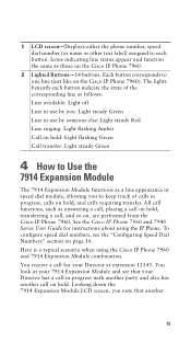
... flashing Green Call transfer: Light steady Green 4 How to Use the 7914 Expansion Module The 7914 Expansion Module functions as answering a call, placing a call for instructions about using the Cisco IP Phone 7960 and 7914 Expansion Module combination. The lights beneath each button. You receive a call on hold . Looking down the 7914 Expansion Module LCD screen, you to keep track of the corresponding line as...
... flashing Green Call transfer: Light steady Green 4 How to Use the 7914 Expansion Module The 7914 Expansion Module functions as answering a call, placing a call for instructions about using the Cisco IP Phone 7960 and 7914 Expansion Module combination. The lights beneath each button. You receive a call on hold . Looking down the 7914 Expansion Module LCD screen, you to keep track of the corresponding line as...
Quick Start Guide
Page 16
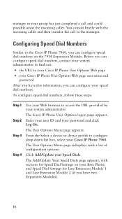
... out: • the URL to your Cisco IP Phone User Options Web page • your Cisco IP Phone User Options Web page user name and password After you have this information, you have two Expansion Modules). 16 The Cisco IP Phone User Options logon page appears. From the ...Cisco IP Phone 7960. Enter your user ID and your Speed Dials. The Add/Update Your Speed Dials page appears, with sections for Speed Dial Settings on your Base Phone, and Speed Dial Settings for Line Extension Module 1 and Line Extension Module 2 (if you can configure speed dial numbers on the 7914 Expansion Module...
... out: • the URL to your Cisco IP Phone User Options Web page • your Cisco IP Phone User Options Web page user name and password After you have this information, you have two Expansion Modules). 16 The Cisco IP Phone User Options logon page appears. From the ...Cisco IP Phone 7960. Enter your user ID and your Speed Dials. The Add/Update Your Speed Dials page appears, with sections for Speed Dial Settings on your Base Phone, and Speed Dial Settings for Line Extension Module 1 and Line Extension Module 2 (if you can configure speed dial numbers on the 7914 Expansion Module...
Quick Start Guide
Page 17
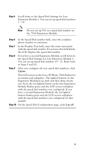
..., the 1st lighted button on the 7914 Expansion Module. Step 7 In the Display Text field, enter the name associated with the speed dial number. Step 6 In the Speed Dial number field, enter the complete phone number or extension. The LCD screen on the Expansion Module(s) go dark and then shine steady...set up speed dial numbers 19 - 32. The lighted buttons on the Cisco IP Phone 7960 flashes for an instant and redisplays. Note Do not set up 911 as a speed dial number on the first Expansion Module flashes green and the LCD screen redisplays with the speed dial numbers you ...
..., the 1st lighted button on the 7914 Expansion Module. Step 7 In the Display Text field, enter the name associated with the speed dial number. Step 6 In the Speed Dial number field, enter the complete phone number or extension. The LCD screen on the Expansion Module(s) go dark and then shine steady...set up speed dial numbers 19 - 32. The lighted buttons on the Cisco IP Phone 7960 flashes for an instant and redisplays. Note Do not set up 911 as a speed dial number on the first Expansion Module flashes green and the LCD screen redisplays with the speed dial numbers you ...
Quick Start Guide
Page 18
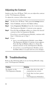
...Contrast, and press the Select softkey. The Expansion Module 2 Contrast screen appears. Step 1 Step 2 Step 3 Step 4 Step 5 On the Cisco IP Phone 7960, press the Settings button. Adjusting the Contrast Similar to the Cisco IP Phone 7960, you are correct. • ...Verify that all of the cable connections are having difficulty using your changes. 5 Troubleshooting Refer to the following table if you can adjust the contrast on the 7914 Expansion Module...
...Contrast, and press the Select softkey. The Expansion Module 2 Contrast screen appears. Step 1 Step 2 Step 3 Step 4 Step 5 On the Cisco IP Phone 7960, press the Settings button. Adjusting the Contrast Similar to the Cisco IP Phone 7960, you are correct. • ...Verify that all of the cable connections are having difficulty using your changes. 5 Troubleshooting Refer to the following table if you can adjust the contrast on the 7914 Expansion Module...
Quick Start Guide
Page 19
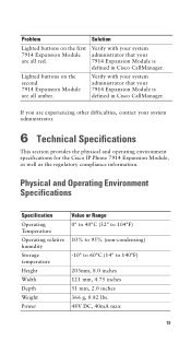
... administrator. 6 Technical Specifications This section provides the physical and operating environment specifications for the Cisco IP Phone 7914 Expansion Module, as well as the regulatory compliance information. Lighted buttons on the first 7914 Expansion Module are experiencing other difficulties, contact your 7914 Expansion Module is defined in Cisco CallManager. Physical and Operating Environment Specifications Specification Operating Temperature Operating relative humidity Storage temperature Height...
... administrator. 6 Technical Specifications This section provides the physical and operating environment specifications for the Cisco IP Phone 7914 Expansion Module, as well as the regulatory compliance information. Lighted buttons on the first 7914 Expansion Module are experiencing other difficulties, contact your 7914 Expansion Module is defined in Cisco CallManager. Physical and Operating Environment Specifications Specification Operating Temperature Operating relative humidity Storage temperature Height...
Quick Start Guide
Page 21
... Translated documentation is available at this URL: http://www.cisco.com/public/countries_languages.shtml 21 7 For More Information The following documents provide additional information. • Cisco IP Phone Administration Guide for Cisco CallManager-Provides instructions for the system administrator about configuring the 7914 Expansion Module in Cisco CallManager. http://www.cisco.com/univercd/cc/td/doc/product/voice/ c_callmg/index...
... Translated documentation is available at this URL: http://www.cisco.com/public/countries_languages.shtml 21 7 For More Information The following documents provide additional information. • Cisco IP Phone Administration Guide for Cisco CallManager-Provides instructions for the system administrator about configuring the 7914 Expansion Module in Cisco CallManager. http://www.cisco.com/univercd/cc/td/doc/product/voice/ c_callmg/index...


