Hardware Installation Guide
Page 11
... before placing a service call. 78-5373-04 Cisco 800 Series Routers Hardware Installation Guide xi In addition, Cisco Technical Assistance Center (TAC) engineers provide telephone support. You can work from the Cisco Technical Support Website by copying and pasting show an illustration of...online support resources. The Cisco Technical Support Website on your reseller. The correct public key to all customers, partners, resellers, and distributors who hold a valid Cisco service contract, contact your product and record the information before submitting a web or phone request ...
... before placing a service call. 78-5373-04 Cisco 800 Series Routers Hardware Installation Guide xi In addition, Cisco Technical Assistance Center (TAC) engineers provide telephone support. You can work from the Cisco Technical Support Website by copying and pasting show an illustration of...online support resources. The Cisco Technical Support Website on your reseller. The correct public key to all customers, partners, resellers, and distributors who hold a valid Cisco service contract, contact your product and record the information before submitting a web or phone request ...

Hardware Installation Guide
Page 19
... Connect to ISDN wall jack. Telephone ports Connect to physically secure router. Locking power connector Connect power supply. 11667 Figure 1-6 Cisco 803 Router Back Panel Ethernet ports Connect Ethernet network devices. Ethernet port Connect Ethernet network device. Power switch l = On. = Standby or no power output. PHONE 1 2 Locking power connector Connect power supply. 78-5373-04...
... Connect to ISDN wall jack. Telephone ports Connect to physically secure router. Locking power connector Connect power supply. 11667 Figure 1-6 Cisco 803 Router Back Panel Ethernet ports Connect Ethernet network devices. Ethernet port Connect Ethernet network device. Power switch l = On. = Standby or no power output. PHONE 1 2 Locking power connector Connect power supply. 78-5373-04...

Hardware Installation Guide
Page 20
... Connect to physically secure router. Figure 1-8 Cisco 802 IDSL Router Back Panel Link LED Indicates state of Ethernet port. LINK TO TO HUB PC ETHERNET 10 BASE T CONSOLE Cisco 802 IDSL IDSL Cable lock Use cable lock to telephone, fax machine, or modem. Cisco 804 CONSOLE ISDN U Console port Connect PC or terminal. PHONE 1 2 Locking power connector...
... Connect to physically secure router. Figure 1-8 Cisco 802 IDSL Router Back Panel Link LED Indicates state of Ethernet port. LINK TO TO HUB PC ETHERNET 10 BASE T CONSOLE Cisco 802 IDSL IDSL Cable lock Use cable lock to telephone, fax machine, or modem. Cisco 804 CONSOLE ISDN U Console port Connect PC or terminal. PHONE 1 2 Locking power connector...
Hardware Installation Guide
Page 30
... the LED is on after you can damage your hub connection, verify that one of router HUB/NO HUB button. Cisco 803 router 2. HUB NO HUB ETHERNET 10 BASE T 0 1 2 3 Cisco 803 CONSOLE ISDN S/T PHONE 1 2 Cisco Micro Hub 10/100 11674 1X 101S00PBBEaasEseeDTTX LED SOLID BLINK 1 5 2 6 3 7 4 8 2X ETHERNET 3X 4X 6X 7X 8X MDI MDI-X 3. Connect other...
... the LED is on after you can damage your hub connection, verify that one of router HUB/NO HUB button. Cisco 803 router 2. HUB NO HUB ETHERNET 10 BASE T 0 1 2 3 Cisco 803 CONSOLE ISDN S/T PHONE 1 2 Cisco Micro Hub 10/100 11674 1X 101S00PBBEaasEseeDTTX LED SOLID BLINK 1 5 2 6 3 7 4 8 2X ETHERNET 3X 4X 6X 7X 8X MDI MDI-X 3. Connect other...
Hardware Installation Guide
Page 31
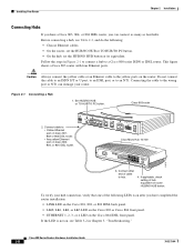
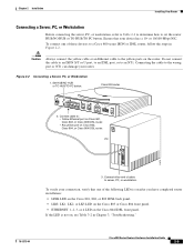
... device has a 10- Set HUB/NO HUB or TO HUB/TO PC button. or 10/100-Mbps NIC. Cisco 803 router HUB NO HUB ETHERNET 10 BASE T 0 1 2 3 Cisco 803 CONSOLE ISDN S/T PHONE 1 2 2. Chapter 2 Installation Installing Your Router Connecting a Server, PC, or Workstation Before connecting the server, PC, or workstation, refer to Table 2-2 to determine how...
... device has a 10- Set HUB/NO HUB or TO HUB/TO PC button. or 10/100-Mbps NIC. Cisco 803 router HUB NO HUB ETHERNET 10 BASE T 0 1 2 3 Cisco 803 CONSOLE ISDN S/T PHONE 1 2 2. Chapter 2 Installation Installing Your Router Connecting a Server, PC, or Workstation Before connecting the server, PC, or workstation, refer to Table 2-2 to determine how...
Hardware Installation Guide
Page 33
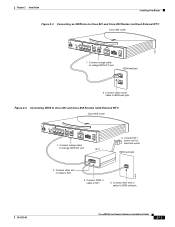
... cable to Cisco 801 and Cisco 803 Routers (with External NT1) Cisco 803 router HUB NO HUB ETHERNET 10 BASE T 0 1 2 3 Cisco 803 CONSOLE ISDN S/T PHONE 1 2 1. Figure 2-4 Connecting ISDN to ISDN wall jack. 11676 78-5373-04 Cisco 800 Series Routers Hardware Installation Guide 2-11 Connect other end of cable to Cisco 801 and Cisco 803 Routers (without External NT1) Cisco 803 router 11677 HUB...
... cable to Cisco 801 and Cisco 803 Routers (with External NT1) Cisco 803 router HUB NO HUB ETHERNET 10 BASE T 0 1 2 3 Cisco 803 CONSOLE ISDN S/T PHONE 1 2 1. Figure 2-4 Connecting ISDN to ISDN wall jack. 11676 78-5373-04 Cisco 800 Series Routers Hardware Installation Guide 2-11 Connect other end of cable to Cisco 801 and Cisco 803 Routers (without External NT1) Cisco 803 router 11677 HUB...
Hardware Installation Guide
Page 35
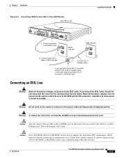
...cable to standby. Connect other devices. 78-5373-04 Cisco 800 Series Routers Hardware Installation Guide 2-13 Caution Cisco 802 IDSL and Cisco 804 IDSL routers do not support the Australian IUT requirement, which specifies that the routers must communicate for 1/2 hour after a power failure.... is turned to ISDN wall jack. Do not connect the cable to Cisco 802 or Cisco 804 Routers Cisco 804 router Installing Your Router HUB NO HUB ETHERNET 10 BASE T 0 1 2 3 Cisco 804 CONSOLE ISDN U PHONE 1 2 1. Connecting an IDSL Line Warning Network hazardous voltages are present...
...cable to standby. Connect other devices. 78-5373-04 Cisco 800 Series Routers Hardware Installation Guide 2-13 Caution Cisco 802 IDSL and Cisco 804 IDSL routers do not support the Australian IUT requirement, which specifies that the routers must communicate for 1/2 hour after a power failure.... is turned to ISDN wall jack. Do not connect the cable to Cisco 802 or Cisco 804 Routers Cisco 804 router Installing Your Router HUB NO HUB ETHERNET 10 BASE T 0 1 2 3 Cisco 804 CONSOLE ISDN U PHONE 1 2 1. Connecting an IDSL Line Warning Network hazardous voltages are present...
Hardware Installation Guide
Page 37
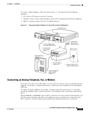
... 6. Connect NT1 power cord to orange ISDN S/T port. 2. Chapter 2 Installation Installing Your Router To connect a digital telephone, follow the steps in Figure 2-7. Connect ISDN U cable to Cisco 801 and Cisco 803 Routers Cisco 803 router HUB NO HUB ETHERNET 10 BASE T 0 1 2 3 Cisco 803 CONSOLE ISDN S/T PHONE 1 2 1. You must provide the following equipment: • NT1 with two S/T interfaces and...
... 6. Connect NT1 power cord to orange ISDN S/T port. 2. Chapter 2 Installation Installing Your Router To connect a digital telephone, follow the steps in Figure 2-7. Connect ISDN U cable to Cisco 801 and Cisco 803 Routers Cisco 803 router HUB NO HUB ETHERNET 10 BASE T 0 1 2 3 Cisco 803 CONSOLE ISDN S/T PHONE 1 2 1. You must provide the following equipment: • NT1 with two S/T interfaces and...
Hardware Installation Guide
Page 38
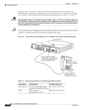
... 2 Installation telephones, faxes, or modems to Cisco 803 and Cisco 804 Routers Cisco 804 router HUB NO HUB ETHERNET 10 BASE T 0 1 2 3 Cisco 804 CONSOLE ISDN U PHONE 1 2 1. Warning This equipment contains a ring signal generator (ringer), which causes incoming calls to telephone, fax machine, or modem. The ringer is active. Figure 2-8 Connecting an ...
... 2 Installation telephones, faxes, or modems to Cisco 803 and Cisco 804 Routers Cisco 804 router HUB NO HUB ETHERNET 10 BASE T 0 1 2 3 Cisco 804 CONSOLE ISDN U PHONE 1 2 1. Warning This equipment contains a ring signal generator (ringer), which causes incoming calls to telephone, fax machine, or modem. The ringer is active. Figure 2-8 Connecting an ...
Hardware Installation Guide
Page 39
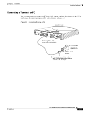
...via the CLI or troubleshoot. Connect light blue cable to terminal or PC. Figure 2-9 Connecting Terminal or PC Cisco 804 router 11680 HUB NO HUB ETHERNET 10 BASE T 0 1 2 3 Cisco 804 CONSOLE ISDN U PHONE 1 2 1. DB-X-to-RJ-45 adapter 2. To connect a terminal or PC, follow the steps in ...Figure 2-9. Chapter 2 Installation Installing Your Router Connecting a Terminal or PC You can connect either DB-9-to-RJ-45 adapter ...
...via the CLI or troubleshoot. Connect light blue cable to terminal or PC. Figure 2-9 Connecting Terminal or PC Cisco 804 router 11680 HUB NO HUB ETHERNET 10 BASE T 0 1 2 3 Cisco 804 CONSOLE ISDN U PHONE 1 2 1. DB-X-to-RJ-45 adapter 2. To connect a terminal or PC, follow the steps in ...Figure 2-9. Chapter 2 Installation Installing Your Router Connecting a Terminal or PC You can connect either DB-9-to-RJ-45 adapter ...
Hardware Installation Guide
Page 40
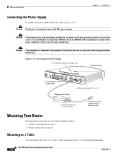
...other horizontal surface • Wall or other vertical surface Mounting on a Table You can mount your router on a table or other end of the following guidelines: 2-18 Cisco 800 Series Routers Hardware Installation Guide 78-5373-04 Press power switch to on one of power cord to power ... to work with TN power systems. Warning This product relies on the phase conductors (all current-carrying conductors). Cisco 803 CONSOLE ISDN S/T PHONE 1 2 5. Mounting Your Router Chapter 2 Installation Connecting the Power Supply To connect the power supply, follow the steps in Figure 2-10.
...other horizontal surface • Wall or other vertical surface Mounting on a Table You can mount your router on a table or other end of the following guidelines: 2-18 Cisco 800 Series Routers Hardware Installation Guide 78-5373-04 Press power switch to on one of power cord to power ... to work with TN power systems. Warning This product relies on the phase conductors (all current-carrying conductors). Cisco 803 CONSOLE ISDN S/T PHONE 1 2 5. Mounting Your Router Chapter 2 Installation Connecting the Power Supply To connect the power supply, follow the steps in Figure 2-10.
Hardware Installation Guide
Page 53
... America, telephone service providers typically provide an S/T interface. The U interface is a two-wire (single pair) interface from the phone switch that supports full-duplex data transfer over two pairs of wires. Cisco 803 and Cisco 804 routers support data and voice applications. The B channel operates at 16 kbps and carries control and signaling information although it...
... America, telephone service providers typically provide an S/T interface. The U interface is a two-wire (single pair) interface from the phone switch that supports full-duplex data transfer over two pairs of wires. Cisco 803 and Cisco 804 routers support data and voice applications. The B channel operates at 16 kbps and carries control and signaling information although it...
