Getting Started Guide
Page 4
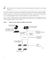
... controller network topology and network connections, showing the medium dependent interface (MDI) Ethernet cables required. To best use straight-through or crossover cables. Figure 1 Typical Controller Topology and Network Connections Console emulator for initial boot-up Null modem serial cable (DB-9 -> RJ-45) to console connection Cisco WCS software, web user interface 10/100/1000BASE-T MDI...
... controller network topology and network connections, showing the medium dependent interface (MDI) Ethernet cables required. To best use straight-through or crossover cables. Figure 1 Typical Controller Topology and Network Connections Console emulator for initial boot-up Null modem serial cable (DB-9 -> RJ-45) to console connection Cisco WCS software, web user interface 10/100/1000BASE-T MDI...
Getting Started Guide
Page 7
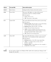
... Amber-Controller status activity, such as firmware upgrade. • Blinking Amber-Controller error. Caution Do not connect a Power over Ethernet (PoE) cable to the system The system LED determines if the system is on when all the power conversion circuits are running normally. LED description: •...7 For example, a temperature error exists. A status or error message is posted on the console screen. • Off-System not receiving power. The status or error is posted on the console screen. Callout RESET PWR Port and LEDs Reset button Power LED SYS System LED ALM Alarm...
... Amber-Controller status activity, such as firmware upgrade. • Blinking Amber-Controller error. Caution Do not connect a Power over Ethernet (PoE) cable to the system The system LED determines if the system is on when all the power conversion circuits are running normally. LED description: •...7 For example, a temperature error exists. A status or error message is posted on the console screen. • Off-System not receiving power. The status or error is posted on the console screen. Callout RESET PWR Port and LEDs Reset button Power LED SYS System LED ALM Alarm...
Getting Started Guide
Page 9
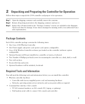
... damage. If any item is damaged or missing, notify your authorized Cisco sales representative. Network, operating system service network, and access point cables as required • Command-line interface (CLI) console - Package Contents Each 2504 controller package contains the following items: • One Cisco 2504 Wireless Controller. • One Power supply and power cord...
... damage. If any item is damaged or missing, notify your authorized Cisco sales representative. Network, operating system service network, and access point cables as required • Command-line interface (CLI) console - Package Contents Each 2504 controller package contains the following items: • One Cisco 2504 Wireless Controller. • One Power supply and power cord...

Getting Started Guide
Page 11
...the Controller This section includes the following installation procedures: • Mounting the Controller, page 11 • Connecting the Controller Console Port, page 21 • Securing the Power Adapter Cable, page 21 • Installing a Security Lock, page 23 Mounting the Controller This section includes the following these guidelines: ...and reliable if you install it is within 328 ft. (100 m) of Radio Resource Management (RRM), either enabled or disabled. Leave at cisco.com. • Status of the 802.11a, 802.11b, 802.11g, or 802.11n networks, either enabled or disabled. • ...
...the Controller This section includes the following installation procedures: • Mounting the Controller, page 11 • Connecting the Controller Console Port, page 21 • Securing the Power Adapter Cable, page 21 • Installing a Security Lock, page 23 Mounting the Controller This section includes the following these guidelines: ...and reliable if you install it is within 328 ft. (100 m) of Radio Resource Management (RRM), either enabled or disabled. Leave at cisco.com. • Status of the 802.11a, 802.11b, 802.11g, or 802.11n networks, either enabled or disabled. • ...

Getting Started Guide
Page 13
... Controller on a Wall (Rack-Mount Brackets) The controller can order a kit with 19-inch rack mounting brackets and hardware from Cisco. Warning Read the wall-mounting carefully before beginning installation. Note Allow 3 inches of the 2504 controller as shown in Figure 5 with... mounted on a shelf or desk, perform the following tasks to complete the installation: • Connecting the Controller Console Port • Securing the Power Adapter Cable • Connecting to the Network For configuration instructions about using rack-mount brackets, follow the correct procedures could result...
... Controller on a Wall (Rack-Mount Brackets) The controller can order a kit with 19-inch rack mounting brackets and hardware from Cisco. Warning Read the wall-mounting carefully before beginning installation. Note Allow 3 inches of the 2504 controller as shown in Figure 5 with... mounted on a shelf or desk, perform the following tasks to complete the installation: • Connecting the Controller Console Port • Securing the Power Adapter Cable • Connecting to the Network For configuration instructions about using rack-mount brackets, follow the correct procedures could result...

Getting Started Guide
Page 15
... Script and Power-On Self Test" section on the wall, perform the following tasks to complete the installation: • Connecting the Controller Console Port • Securing the Power Adapter Cable • Connecting to the Network For configuration instructions about using mounting screws, always mount the controller with the front panel facing down...
... Script and Power-On Self Test" section on the wall, perform the following tasks to complete the installation: • Connecting the Controller Console Port • Securing the Power Adapter Cable • Connecting to the Network For configuration instructions about using mounting screws, always mount the controller with the front panel facing down...
Getting Started Guide
Page 17
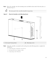
Step 4 Place the controller onto the mounting screws and slide it lock into place, as shown in Figure 8. Note The front panel of the controller should be facing down until it down . Figure 8 Place the Controller on the Mounting Screws 282085 2 1 2 1 Front panel (facing down) 2 Mounting screws Step 5 After the controller is mounted ion the wall, perform the following tasks to complete the installation: • Connecting the Controller Console Port • Securing the Power Adapter Cable • Connecting to the Network 17
Step 4 Place the controller onto the mounting screws and slide it lock into place, as shown in Figure 8. Note The front panel of the controller should be facing down until it down . Figure 8 Place the Controller on the Mounting Screws 282085 2 1 2 1 Front panel (facing down) 2 Mounting screws Step 5 After the controller is mounted ion the wall, perform the following tasks to complete the installation: • Connecting the Controller Console Port • Securing the Power Adapter Cable • Connecting to the Network 17

Getting Started Guide
Page 20
Figure 10 Mounting the Controller in a 19-Inch Rack 1 282086 1 #10-32 pan-head screws or #12-24 slotted head screws Step 3 Step 4 After the controller is mounted in the rack, perform the following tasks to complete the installation: • Connecting the Controller Console Port • Securing the Power Adapter Cable • Connecting to the Network For configuration instructions about using the CLI setup program, see the "Running the Bootup Script and Power-On Self Test" section on page 23. 20
Figure 10 Mounting the Controller in a 19-Inch Rack 1 282086 1 #10-32 pan-head screws or #12-24 slotted head screws Step 3 Step 4 After the controller is mounted in the rack, perform the following tasks to complete the installation: • Connecting the Controller Console Port • Securing the Power Adapter Cable • Connecting to the Network For configuration instructions about using the CLI setup program, see the "Running the Bootup Script and Power-On Self Test" section on page 23. 20
Getting Started Guide
Page 21
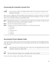
...: Step 1 Step 2 Step 3 Plug the RJ-45 connector on a null-modem serial cable into the controller console port and the other end of the cable into the serial port of the PC. The clip relieves the cable in the event it to connect it falls and prevents the connector from being sheared... off at the plug pins. Before you can be damaged if the power cable is not compatible with the cable. Note The Cisco 2106 power adapter is pulled or if the power adapter falls. Start the PC terminal emulation program. Configure the terminal ...
...: Step 1 Step 2 Step 3 Plug the RJ-45 connector on a null-modem serial cable into the controller console port and the other end of the cable into the serial port of the PC. The clip relieves the cable in the event it to connect it falls and prevents the connector from being sheared... off at the plug pins. Before you can be damaged if the power cable is not compatible with the cable. Note The Cisco 2106 power adapter is pulled or if the power adapter falls. Start the PC terminal emulation program. Configure the terminal ...
Getting Started Guide
Page 23
...into memory, verifies its operating system software load, and initializes itself with screw 1 2 AC/DC power adapter cable Power plugged into a grounded 100 to 240 VAC, 50-60 Hz electrical outlet. If the Power LED does...the Bootup Script and Power-On Self Test When you should have connected your PC to the CLI console on the controller as the type that the power connections to secure the controller. Plug a country-... appears. You can install an optional customer-supplied cable lock, such as described in the "Connecting the Controller Console Port" section on the back panel.
...into memory, verifies its operating system software load, and initializes itself with screw 1 2 AC/DC power adapter cable Power plugged into a grounded 100 to 240 VAC, 50-60 Hz electrical outlet. If the Power LED does...the Bootup Script and Power-On Self Test When you should have connected your PC to the CLI console on the controller as the type that the power connections to secure the controller. Plug a country-... appears. You can install an optional customer-supplied cable lock, such as described in the "Connecting the Controller Console Port" section on the back panel.
Getting Started Guide
Page 34
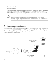
...any changes after 5 minutes of inactivity. Figure 13 External Network Equipment Connection to the Controller 10/100/1000BASE-T MDI cable Cisco Access Points CLI console Connection to the controller. You can change the system prompt to 31 characters. Make sure you enter the new ...802.11 distribution system) to main office Network 34 Firewall Office network 10/100/1000BASE-T MDI cable 282298 Always use Category-5, Category-5e, Category-6, or Category-7 Ethernet cables to connect the office network equipment to the controller. Note The CLI automatically logs out without...
...any changes after 5 minutes of inactivity. Figure 13 External Network Equipment Connection to the Controller 10/100/1000BASE-T MDI cable Cisco Access Points CLI console Connection to the controller. You can change the system prompt to 31 characters. Make sure you enter the new ...802.11 distribution system) to main office Network 34 Firewall Office network 10/100/1000BASE-T MDI cable 282298 Always use Category-5, Category-5e, Category-6, or Category-7 Ethernet cables to connect the office network equipment to the controller. Note The CLI automatically logs out without...
Getting Started Guide
Page 36
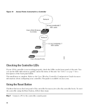
... Points Connected to a Controller Network Cisco 2504 Wireless Controller 10/100/1000BASE-T MDI cable Network 10/100/1000BASE-T MDI cables 282081 Cisco Access Points Checking the Controller LEDs If your controller. Using the Reset Button The Reset button on the front panel of the unit. Refer to the controller console point. 36 The guide is...
... Points Connected to a Controller Network Cisco 2504 Wireless Controller 10/100/1000BASE-T MDI cable Network 10/100/1000BASE-T MDI cables 282081 Cisco Access Points Checking the Controller LEDs If your controller. Using the Reset Button The Reset button on the front panel of the unit. Refer to the controller console point. 36 The guide is...

