Getting Started Guide
Page 1
GETTING STARTED GUIDE Cisco 2500 Series Wireless Controller May 2011 Revised June 2, 2011 1 About This Guide 2 Unpacking and Preparing the Controller for Operation 3 Installing the Controller 4 Running the Bootup Script and Power-On Self Test 5 Logging into the Controller 6 Connecting to the Network 7 What's New in Cisco Product Documentation 8 Translated Safety Warnings
GETTING STARTED GUIDE Cisco 2500 Series Wireless Controller May 2011 Revised June 2, 2011 1 About This Guide 2 Unpacking and Preparing the Controller for Operation 3 Installing the Controller 4 Running the Bootup Script and Power-On Self Test 5 Logging into the Controller 6 Connecting to the Network 7 What's New in Cisco Product Documentation 8 Translated Safety Warnings
Getting Started Guide
Page 2
...the following measures: • Reorient or relocate the receiving antenna. • Increase the separation between the equipment and receiver. • Connect the equipment to an outlet on . If this equipment does cause harmful interference to radio or television reception, which can radiate radio ...symbol means danger. 1 About This Guide This guide is designed to help you install and minimally configure your Cisco 2504 Wireless Controller (2504 controller), which the receiver is connected. • Consult the dealer or an experienced radio/TV technician for help. (cfr reference 15.105) ...
...the following measures: • Reorient or relocate the receiving antenna. • Increase the separation between the equipment and receiver. • Connect the equipment to an outlet on . If this equipment does cause harmful interference to radio or television reception, which can radiate radio ...symbol means danger. 1 About This Guide This guide is designed to help you install and minimally configure your Cisco 2504 Wireless Controller (2504 controller), which the receiver is connected. • Consult the dealer or an experienced radio/TV technician for help. (cfr reference 15.105) ...
Getting Started Guide
Page 4
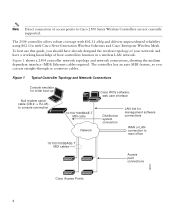
.... Figure 1 Typical Controller Topology and Network Connections Console emulator for initial boot-up Null modem serial cable (DB-9 -> RJ-45) to console connection Cisco WCS software, web user interface 10/100/1000BASE-T MDI cable Network Distribution system connection LAN link for management software connections WAN or LAN connection to Cisco 2500 Series Wireless Controllers are not currently...
.... Figure 1 Typical Controller Topology and Network Connections Console emulator for initial boot-up Null modem serial cable (DB-9 -> RJ-45) to console connection Cisco WCS software, web user interface 10/100/1000BASE-T MDI cable Network Distribution system connection LAN link for management software connections WAN or LAN connection to Cisco 2500 Series Wireless Controllers are not currently...

Getting Started Guide
Page 6
...so that 1500 VAC rms isolation (per the 802.3 specification) is configured to reset the POE controller, it can be used for infra-switch connection using multiple an AP-Manager or data interface. 6 They provide a I2C communications channel between chassis ground and any 48V/Ethernet signal. The ... or Blinking Green-Link activity • Off-No link Note Ports 3 and 4 are RJ-45 connector form-factor. The ports can do not connect access point devices to these ports. If software needs to I2C address 0x40/41 (0100 000r/w). Callout Port and LEDs State and Description 1 GigE ...
...so that 1500 VAC rms isolation (per the 802.3 specification) is configured to reset the POE controller, it can be used for infra-switch connection using multiple an AP-Manager or data interface. 6 They provide a I2C communications channel between chassis ground and any 48V/Ethernet signal. The ... or Blinking Green-Link activity • Off-No link Note Ports 3 and 4 are RJ-45 connector form-factor. The ports can do not connect access point devices to these ports. If software needs to I2C address 0x40/41 (0100 000r/w). Callout Port and LEDs State and Description 1 GigE ...
Getting Started Guide
Page 7
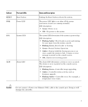
.... LED description: • Blinking Green-Controller image upgrading. • Amber-Controller status activity, such as firmware upgrade. • Blinking Amber-Controller error. Caution Do not connect a Power over Ethernet (PoE) cable to halt. Callout RESET PWR Port and LEDs Reset button Power LED SYS System LED ALM Alarm LED State and...
.... LED description: • Blinking Green-Controller image upgrading. • Amber-Controller status activity, such as firmware upgrade. • Blinking Amber-Controller error. Caution Do not connect a Power over Ethernet (PoE) cable to halt. Callout RESET PWR Port and LEDs Reset button Power LED SYS System LED ALM Alarm LED State and...
Getting Started Guide
Page 9
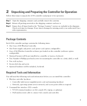
... emulator on the controller (software option configurable). • Optional licenses will need the following items: • One Cisco 2504 Wireless Controller. • One Power supply and power cord (power cord option configurable). • Cisco 2504 Wireless Controller software pre-loaded on CLI console (PC, laptop, or palmtop) - Package Contents Each 2504 controller... service network, and access point cables as required • Command-line interface (CLI) console - 2 Unpacking and Preparing the Controller for Operation Follow these steps to connect CLI console and controller 9
... emulator on the controller (software option configurable). • Optional licenses will need the following items: • One Cisco 2504 Wireless Controller. • One Power supply and power cord (power cord option configurable). • Cisco 2504 Wireless Controller software pre-loaded on CLI console (PC, laptop, or palmtop) - Package Contents Each 2504 controller... service network, and access point cables as required • Command-line interface (CLI) console - 2 Unpacking and Preparing the Controller for Operation Follow these steps to connect CLI console and controller 9

Getting Started Guide
Page 11
...both sides and rear of the controller. • Verify that the ambient temperature remains between 32 to 104° F (0 to the Cisco Wireless LAN Controller Configuration Guide for this installation. Choosing a Physical Location You can reach the controller and all cables attached to it. &#... electrical outlet. 3 Installing the Controller This section includes the following installation procedures: • Mounting the Controller, page 11 • Connecting the Controller Console Port, page 21 • Securing the Power Adapter Cable, page 21 • Installing a Security Lock, page 23...
...both sides and rear of the controller. • Verify that the ambient temperature remains between 32 to 104° F (0 to the Cisco Wireless LAN Controller Configuration Guide for this installation. Choosing a Physical Location You can reach the controller and all cables attached to it. &#... electrical outlet. 3 Installing the Controller This section includes the following installation procedures: • Mounting the Controller, page 11 • Connecting the Controller Console Port, page 21 • Securing the Power Adapter Cable, page 21 • Installing a Security Lock, page 23...

Getting Started Guide
Page 13
... controller is mounted on a shelf or desk, perform the following tasks to complete the installation: • Connecting the Controller Console Port • Securing the Power Adapter Cable • Connecting to the system. The kit part number is not included with the controller. Note Allow 3 inches of... the 2504 controller as shown in Figure 5 with 19-inch rack mounting brackets and hardware from Cisco. Statement 378 To mount the ...
... controller is mounted on a shelf or desk, perform the following tasks to complete the installation: • Connecting the Controller Console Port • Securing the Power Adapter Cable • Connecting to the system. The kit part number is not included with the controller. Note Allow 3 inches of... the 2504 controller as shown in Figure 5 with 19-inch rack mounting brackets and hardware from Cisco. Statement 378 To mount the ...

Getting Started Guide
Page 15
... Step 3 Step 4 After the controller is mounted on the wall, perform the following tasks to complete the installation: • Connecting the Controller Console Port • Securing the Power Adapter Cable • Connecting to the Network For configuration instructions about using the CLI setup program, see the "Running the Bootup Script and Power...
... Step 3 Step 4 After the controller is mounted on the wall, perform the following tasks to complete the installation: • Connecting the Controller Console Port • Securing the Power Adapter Cable • Connecting to the Network For configuration instructions about using the CLI setup program, see the "Running the Bootup Script and Power...
Getting Started Guide
Page 17
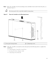
Note The front panel of the controller should be facing down ) 2 Mounting screws Step 5 After the controller is mounted ion the wall, perform the following tasks to complete the installation: • Connecting the Controller Console Port • Securing the Power Adapter Cable • Connecting to the Network 17 Figure 8 Place the Controller on the Mounting Screws 282085 2 1 2 1 Front panel (facing down . Step 4 Place the controller onto the mounting screws and slide it down until it lock into place, as shown in Figure 8.
Note The front panel of the controller should be facing down ) 2 Mounting screws Step 5 After the controller is mounted ion the wall, perform the following tasks to complete the installation: • Connecting the Controller Console Port • Securing the Power Adapter Cable • Connecting to the Network 17 Figure 8 Place the Controller on the Mounting Screws 282085 2 1 2 1 Front panel (facing down . Step 4 Place the controller onto the mounting screws and slide it down until it lock into place, as shown in Figure 8.

Getting Started Guide
Page 20
Figure 10 Mounting the Controller in a 19-Inch Rack 1 282086 1 #10-32 pan-head screws or #12-24 slotted head screws Step 3 Step 4 After the controller is mounted in the rack, perform the following tasks to complete the installation: • Connecting the Controller Console Port • Securing the Power Adapter Cable • Connecting to the Network For configuration instructions about using the CLI setup program, see the "Running the Bootup Script and Power-On Self Test" section on page 23. 20
Figure 10 Mounting the Controller in a 19-Inch Rack 1 282086 1 #10-32 pan-head screws or #12-24 slotted head screws Step 3 Step 4 After the controller is mounted in the rack, perform the following tasks to complete the installation: • Connecting the Controller Console Port • Securing the Power Adapter Cable • Connecting to the Network For configuration instructions about using the CLI setup program, see the "Running the Bootup Script and Power-On Self Test" section on page 23. 20
Getting Started Guide
Page 21
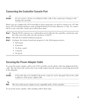
...cable is pulled or if the power adapter falls. Doing so will damage the controller. The clip relieves the cable in the event it to connect it falls and prevents the connector from being sheared off at the plug pins. Caution If the relief clip is not compatible with the cable.... Note The Cisco 2106 power adapter is not installed, the power connector can configure the 2504 controller for the following parameters: • 9600 baud • 8 data bits ...
...cable is pulled or if the power adapter falls. Doing so will damage the controller. The clip relieves the cable in the event it to connect it falls and prevents the connector from being sheared off at the plug pins. Caution If the relief clip is not compatible with the cable.... Note The Cisco 2106 power adapter is not installed, the power connector can configure the 2504 controller for the following parameters: • 9600 baud • 8 data bits ...
Getting Started Guide
Page 23
... 48VDC 3 port. Installing a Security Lock The controller has a security slot on page 21. The Bootloader Options menu appears. Before performing this test, you should have connected your PC to the controller are correct. 23 You can install an optional customer-supplied cable lock, such as the type that the power...
... 48VDC 3 port. Installing a Security Lock The controller has a security slot on page 21. The Bootloader Options menu appears. Before performing this test, you should have connected your PC to the controller are correct. 23 You can install an optional customer-supplied cable lock, such as the type that the power...
Getting Started Guide
Page 30
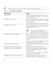
... The default administrative username is the name you must enter a password. Management Interface IP Address Management Interface Netmask Management Interface Default Router Management Interface VLAN Identifier Management Interface Port Num [1 to this controller. Ports values are 1 to the previous command line. The.... Enter the VLAN identifier of the management interface (a valid VLAN identifier or 0 for in-band management of the controller and connectivity to 24 ASCII characters for each . Note Press the hyphen key if you need to return to 4. 30 You can enter...
... The default administrative username is the name you must enter a password. Management Interface IP Address Management Interface Netmask Management Interface Default Router Management Interface VLAN Identifier Management Interface Port Num [1 to this controller. Ports values are 1 to the previous command line. The.... Enter the VLAN identifier of the management interface (a valid VLAN identifier or 0 for in-band management of the controller and connectivity to 24 ASCII characters for each . Note Press the hyphen key if you need to return to 4. 30 You can enter...
Getting Started Guide
Page 34
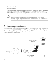
Figure 13 External Network Equipment Connection to the Controller 10/100/1000BASE-T MDI cable Cisco Access Points CLI console Connection to the controller. Note The CLI automatically logs out without saving any alphanumeric string up to CISCO2504, enter config ...prompt "CISCO2504" and press Enter. Always use Category-5, Category-5e, Category-6, or Category-7 Ethernet cables to connect the office ...
Figure 13 External Network Equipment Connection to the Controller 10/100/1000BASE-T MDI cable Cisco Access Points CLI console Connection to the controller. Note The CLI automatically logs out without saving any alphanumeric string up to CISCO2504, enter config ...prompt "CISCO2504" and press Enter. Always use Category-5, Category-5e, Category-6, or Category-7 Ethernet cables to connect the office ...
Getting Started Guide
Page 35
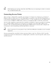
... automatically configures the access point to start transmitting and allowing clients to make the connections. Refer to the Cisco Wireless LAN Controller Configuration Guide for information on configuring the controller to connect access that are not currently supported. As soon as shown in its database....records the access point MAC address in Figure 14. Note Direct connection of access points to a hub or a switch, use Category-5, Category-5e, Category-6, or Category-7 Ethernet cables to connect up to 50 Cisco lightweight access points to the controller Ethernet ports or to the ...
... automatically configures the access point to start transmitting and allowing clients to make the connections. Refer to the Cisco Wireless LAN Controller Configuration Guide for information on configuring the controller to connect access that are not currently supported. As soon as shown in its database....records the access point MAC address in Figure 14. Note Direct connection of access points to a hub or a switch, use Category-5, Category-5e, Category-6, or Category-7 Ethernet cables to connect up to 50 Cisco lightweight access points to the controller Ethernet ports or to the ...
Getting Started Guide
Page 36
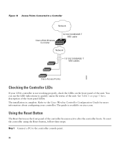
... for more information about configuring your 2504 controller is not working properly, check the LEDs on cisco.com. To reset the controller using the Reset button, follow these steps: Step 1 Connect a PC to the controller console point. 36 The installation is available on the front panel of... the front panel LEDs. Figure 14 Access Points Connected to a Controller Network Cisco 2504 Wireless Controller 10/100/1000BASE-T MDI cable Network...
... for more information about configuring your 2504 controller is not working properly, check the LEDs on cisco.com. To reset the controller using the Reset button, follow these steps: Step 1 Connect a PC to the controller console point. 36 The installation is available on the front panel of... the front panel LEDs. Figure 14 Access Points Connected to a Controller Network Cisco 2504 Wireless Controller 10/100/1000BASE-T MDI cable Network...

Getting Started Guide
Page 55
... standard of UL-certified cables (that have the "UL" or "CSA" shown on the cord), not regulated with the subject law by Cisco. Install and use the provided or designated connection cables/power cables/AC adaptors/batteries. Using any other cables/adaptors could cause a malfunction or a fire. Electrical Appliance and Material Safety...
... standard of UL-certified cables (that have the "UL" or "CSA" shown on the cord), not regulated with the subject law by Cisco. Install and use the provided or designated connection cables/power cables/AC adaptors/batteries. Using any other cables/adaptors could cause a malfunction or a fire. Electrical Appliance and Material Safety...


