Hardware Installation Guide
Page 3
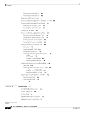
... Requirements 1-5 Preparing for Installation 2-1 Overview 2-1 Installation Overview 2-1 Safety Recommendations 2-2 Maintaining Safety with Electricity 2-2 Preventing Electrostatic Discharge Damage 2-3 General Site Requirements 2-4 Site Environment 2-4 Preventive Site Configuration 2-4 Power Supply Considerations 2-4 Configuring Equipment Racks 2-6 Installing the Adaptive Security Appliance 3-1 Installing the Adaptive Security Appliance 3-1 Rack-Mounting the Chassis 3-2 Setting the Chassis on a Desktop 3-3 Connecting the...
... Requirements 1-5 Preparing for Installation 2-1 Overview 2-1 Installation Overview 2-1 Safety Recommendations 2-2 Maintaining Safety with Electricity 2-2 Preventing Electrostatic Discharge Damage 2-3 General Site Requirements 2-4 Site Environment 2-4 Preventive Site Configuration 2-4 Power Supply Considerations 2-4 Configuring Equipment Racks 2-6 Installing the Adaptive Security Appliance 3-1 Installing the Adaptive Security Appliance 3-1 Rack-Mounting the Chassis 3-2 Setting the Chassis on a Desktop 3-3 Connecting the...
Hardware Installation Guide
Page 4
... Working in an ESD Environment 4-3 Removing and Replacing a Lithium Battery in the SSM 4-4 Removing and Replacing the Power Supply 4-4 Removing the AC Power Supply 4-4 Replacing the AC Power Supply 4-6 Installing the DC Model 4-7 Removing and Replacing the CompactFlash 4-10 Removing the System CompactFlash 4-10 Replacing the System... 4-20 Installing and Replacing the AIP/CSC SSM 4-21 Installing the AIP/CSC SSM 4-21 Replacing the AIP/CSC SSM 4-22 Upgrading Memory for the Cisco ASA 5510 4-22 Removing the DIMM 4-23 Installing the DIMM 4-25 4-26 1 A P P E N D I X Cable Pinouts 1-1 10/100/1000BaseT...
... Working in an ESD Environment 4-3 Removing and Replacing a Lithium Battery in the SSM 4-4 Removing and Replacing the Power Supply 4-4 Removing the AC Power Supply 4-4 Replacing the AC Power Supply 4-6 Installing the DC Model 4-7 Removing and Replacing the CompactFlash 4-10 Removing the System CompactFlash 4-10 Replacing the System... 4-20 Installing and Replacing the AIP/CSC SSM 4-21 Installing the AIP/CSC SSM 4-21 Replacing the AIP/CSC SSM 4-22 Upgrading Memory for the Cisco ASA 5510 4-22 Removing the DIMM 4-23 Installing the DIMM 4-25 4-26 1 A P P E N D I X Cable Pinouts 1-1 10/100/1000BaseT...
Hardware Installation Guide
Page 6
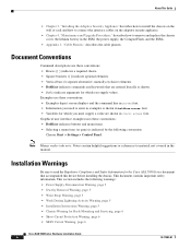
...; Examples depict screen displays and the command line in screen font. • Information you need to read the Regulatory Compliance and Safety Information for the Cisco ASA 5500 Series document that are shown in the SSM, the power supply, the CompactFlash, and the SSMs. • Appendix 1, "Cable Pinouts," describes the cable pinouts.
...; Examples depict screen displays and the command line in screen font. • Information you need to read the Regulatory Compliance and Safety Information for the Cisco ASA 5500 Series document that are shown in the SSM, the power supply, the CompactFlash, and the SSMs. • Appendix 1, "Cable Pinouts," describes the cable pinouts.

Hardware Installation Guide
Page 7
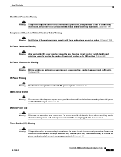
... the system to the terminals. Statement 1004 78-17989-01 Cisco ASA 5500 Series Hardware Installation Guide 5 Statement 12 Jewelry Removal Warning Warning Before working near power supplies, unplug the power cord on equipment that is connected to the card. About This... • Grounded Equipment Warning, page 8 • Safety Cover Requirement, page 8 • Faceplates and Cover Panel Requirement, page 8 Power Supply Disconnection Warning Warning Before working on a chassis or working on AC units; Statement 43 Wrist Strap Warning Warning During this procedure, wear grounding...
... the system to the terminals. Statement 1004 78-17989-01 Cisco ASA 5500 Series Hardware Installation Guide 5 Statement 12 Jewelry Removal Warning Warning Before working near power supplies, unplug the power cord on equipment that is connected to the card. About This... • Grounded Equipment Warning, page 8 • Safety Cover Requirement, page 8 • Faceplates and Cover Panel Requirement, page 8 Power Supply Disconnection Warning Warning Before working on a chassis or working on AC units; Statement 43 Wrist Strap Warning Warning During this procedure, wear grounding...
Hardware Installation Guide
Page 9
... equipment must provide reinforced insulation between the primary AC power and the 48 VDC output. Statement 246 TN Power Warning Warning The device is designed to the ON position. Statement 13 78-17989-01 Cisco ASA 5500 Series Hardware Installation Guide 7 Ensure that the unit... work with TN power systems. Statement 19 48 VDC Power System Warning The customer 48 volt power system must comply with local and national electrical codes. Statement 8 AC Power Disconnection Warning Warning Before working on a chassis or working near power supplies, unplug the power cord on the ...
... equipment must provide reinforced insulation between the primary AC power and the 48 VDC output. Statement 246 TN Power Warning Warning The device is designed to the ON position. Statement 13 78-17989-01 Cisco ASA 5500 Series Hardware Installation Guide 7 Ensure that the unit... work with TN power systems. Statement 19 48 VDC Power System Warning The customer 48 volt power system must comply with local and national electrical codes. Statement 8 AC Power Disconnection Warning Warning Before working on a chassis or working near power supplies, unplug the power cord on the ...
Hardware Installation Guide
Page 12
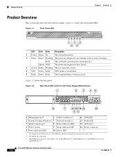
... The CompactFlash is being accessed. Figure 1-2 Rear Panel LEDs and Ports (AC Power Supply Model Shown) 1 2 3 45 CONSOLE AUX MGMT USB2 USB1 119572 FLASH LINK SPD LINK SPD LINK SPD LINK SPD 3 2 1 0 POWER STATUS ACTIVE VPN FLASH 6 7 8 10 12 13 14 9 11 1 ... USB 2.0 interfaces2 Network interfaces3 Power indicator LED 11 VPN LED 12 Flash LED 13 AUX port4 4 Power switch 9 Status indicator LED 14 Power connector 5 Power indicator LED 10 Active LED 1. Figure 1-1 Front Panel LEDs POWER STATUS ACTIVE VPN FLASH CISCO ASA 5540 SERIES Adaptive Security Appliance ...
... The CompactFlash is being accessed. Figure 1-2 Rear Panel LEDs and Ports (AC Power Supply Model Shown) 1 2 3 45 CONSOLE AUX MGMT USB2 USB1 119572 FLASH LINK SPD LINK SPD LINK SPD LINK SPD 3 2 1 0 POWER STATUS ACTIVE VPN FLASH 6 7 8 10 12 13 14 9 11 1 ... USB 2.0 interfaces2 Network interfaces3 Power indicator LED 11 VPN LED 12 Flash LED 13 AUX port4 4 Power switch 9 Status indicator LED 14 Power connector 5 Power indicator LED 10 Active LED 1. Figure 1-1 Front Panel LEDs POWER STATUS ACTIVE VPN FLASH CISCO ASA 5540 SERIES Adaptive Security Appliance ...
Hardware Installation Guide
Page 18
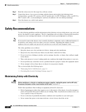
...Warning Before working on a chassis or working near power supplies, unplug the power cord on a stable work surface. The list of the chassis, locate the emergency power-off the power. • Do not work space. • Never assume that power is disconnected from walk areas where you and ...dust-free before, during and after installation. • Keep tools away from a circuit; Statement 12 Follow these guidelines when working . Cisco ASA 5500 Series Hardware Installation Guide 2-2 78-17989-01 Place the chassis on AC units; Upgrading the adaptive security appliance does not require ...
...Warning Before working on a chassis or working near power supplies, unplug the power cord on a stable work surface. The list of the chassis, locate the emergency power-off the power. • Do not work space. • Never assume that power is disconnected from walk areas where you and ...dust-free before, during and after installation. • Keep tools away from a circuit; Statement 12 Follow these guidelines when working . Cisco ASA 5500 Series Hardware Installation Guide 2-2 78-17989-01 Place the chassis on AC units; Upgrading the adaptive security appliance does not require ...
Hardware Installation Guide
Page 19
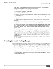
...the DC input wiring on a DC source capable of the victim and then call for the Cisco ASA 5500 Series document. • The adaptive security appliance models equipped with AC-input power supplies are shipped with a 3-wire electrical cord with a grounding-type plug that the chassis is... required at the 48 VDC facility power source. An easily accessible disconnect device should be between 1 and 10 megohms (Mohms). 78-17989-01 Cisco ASA 5500 Series Hardware ...
...the DC input wiring on a DC source capable of the victim and then call for the Cisco ASA 5500 Series document. • The adaptive security appliance models equipped with AC-input power supplies are shipped with a 3-wire electrical cord with a grounding-type plug that the chassis is... required at the 48 VDC facility power source. An easily accessible disconnect device should be between 1 and 10 megohms (Mohms). 78-17989-01 Cisco ASA 5500 Series Hardware ...
Hardware Installation Guide
Page 20
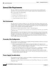
...not be adequate to cool equipment to flow effectively within it on power supply considerations including environmental operating ranges and power requirements, see table 7 at the following url: http://www.cisco.com/en/US/prod/collateral/vpndevc/ps6032/ps6094/ps6120/product_data_sheet0900a ecd802930c5.html... information on physical specifications, see table 7 at the following url: http://www.cisco.com/en/US/prod/collateral/vpndevc/ps6032/ps6094/ps6120/product_data_sheet0900a ecd802930c5.html Cisco ASA 5500 Series Hardware Installation Guide 2-4 78-17989-01 Ensure that the room in ...
...not be adequate to cool equipment to flow effectively within it on power supply considerations including environmental operating ranges and power requirements, see table 7 at the following url: http://www.cisco.com/en/US/prod/collateral/vpndevc/ps6032/ps6094/ps6120/product_data_sheet0900a ecd802930c5.html... information on physical specifications, see table 7 at the following url: http://www.cisco.com/en/US/prod/collateral/vpndevc/ps6032/ps6094/ps6120/product_data_sheet0900a ecd802930c5.html Cisco ASA 5500 Series Hardware Installation Guide 2-4 78-17989-01 Ensure that the room in ...
Hardware Installation Guide
Page 21
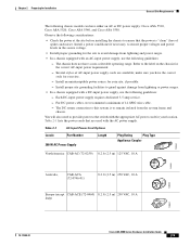
... VAC, 10 A Italy) 120357 78-17989-01 Cisco ASA 5500 Series Hardware Installation Guide 2-5 You will also need to provide power to the switch with a DC-input power supply, use the following guidelines: - The chassis does not have either an AC or DC power supply: Cisco ASA 5510, Cisco ASA 5520, Cisco ASA 5540, and Cisco ASA 5550. Chapter 2 Preparing for Installation General Site Requirements The...
... VAC, 10 A Italy) 120357 78-17989-01 Cisco ASA 5500 Series Hardware Installation Guide 2-5 You will also need to provide power to the switch with a DC-input power supply, use the following guidelines: - The chassis does not have either an AC or DC power supply: Cisco ASA 5510, Cisco ASA 5520, Cisco ASA 5540, and Cisco ASA 5550. Chapter 2 Preparing for Installation General Site Requirements The...
Hardware Installation Guide
Page 35
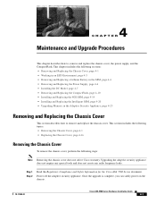
... 1 Step 2 Read the Regulatory Compliance and Safety Information for the Cisco ASA 5500 Series document. Once the upgrade is complete, you can safely power on the chassis. 78-17989-01 Cisco ASA 5500 Series Hardware Installation Guide 4-1 Upgrading the adaptive security appliance does ...Chassis Cover This section describes how to , remove and replace the chassis cover, the power supply, and the CompactFlash. This chapter includes the following steps: Note Removing the chassis cover does not affect Cisco warranty. Power off the adaptive security appliance. 4 C H A P T E R Maintenance ...
... 1 Step 2 Read the Regulatory Compliance and Safety Information for the Cisco ASA 5500 Series document. Once the upgrade is complete, you can safely power on the chassis. 78-17989-01 Cisco ASA 5500 Series Hardware Installation Guide 4-1 Upgrading the adaptive security appliance does ...Chassis Cover This section describes how to , remove and replace the chassis cover, the power supply, and the CompactFlash. This chapter includes the following steps: Note Removing the chassis cover does not affect Cisco warranty. Power off the adaptive security appliance. 4 C H A P T E R Maintenance ...
Hardware Installation Guide
Page 38
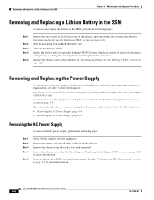
... and pull the battery out. Removing and Replacing the Power Supply For information on power supply considerations including environmental operating ranges and power requirements, see table 7 at the following url: http://www.cisco.com/en/US/prod/collateral/vpndevc/ps6032/ps6094/ps6120/product_data_sheet0900a...power cord and all other cables from the rack if it is available at your local electronics or drug store), by sliding the metal clip back and sliding the battery into place. See the "Installing and Replacing the Intelligent SSM" section on page 4-20 for more information. Cisco ASA...
... and pull the battery out. Removing and Replacing the Power Supply For information on power supply considerations including environmental operating ranges and power requirements, see table 7 at the following url: http://www.cisco.com/en/US/prod/collateral/vpndevc/ps6032/ps6094/ps6120/product_data_sheet0900a...power cord and all other cables from the rack if it is available at your local electronics or drug store), by sliding the metal clip back and sliding the battery into place. See the "Installing and Replacing the Intelligent SSM" section on page 4-20 for more information. Cisco ASA...
Hardware Installation Guide
Page 39
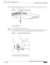
... and pull upward while rocking the connector from side to the chassis, as shown in Figure 4-5. Figure 4-6 Disconnecting the Power Connector 1 119639 2 1 AC power supply 2 Power connector 78-17989-01 Cisco ASA 5500 Series Hardware Installation Guide 4-5 Unlatch the plug, then grasp the sides of the chassis from the surface and unscrew both the screws that...
... and pull upward while rocking the connector from side to the chassis, as shown in Figure 4-5. Figure 4-6 Disconnecting the Power Connector 1 119639 2 1 AC power supply 2 Power connector 78-17989-01 Cisco ASA 5500 Series Hardware Installation Guide 4-5 Unlatch the plug, then grasp the sides of the chassis from the surface and unscrew both the screws that...

Hardware Installation Guide
Page 40
... rear of the adaptive adaptive security appliance. Removing and Replacing the Power Supply Chapter 4 Maintenance and Upgrade Procedures Step 9 Remove the power supply brace by pulling it up and out. Cisco ASA 5500 Series Hardware Installation Guide 4-6 78-17989-01 Figure 4-7 Removing the Power Supply 4 3 119578 2 1 1 Back panel 2 Power supply 3 Power supply brace 4 Front panel Step 10 From the back of the...
... rear of the adaptive adaptive security appliance. Removing and Replacing the Power Supply Chapter 4 Maintenance and Upgrade Procedures Step 9 Remove the power supply brace by pulling it up and out. Cisco ASA 5500 Series Hardware Installation Guide 4-6 78-17989-01 Figure 4-7 Removing the Power Supply 4 3 119578 2 1 1 Back panel 2 Power supply 3 Power supply brace 4 Front panel Step 10 From the back of the...
Hardware Installation Guide
Page 41
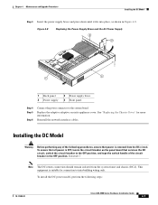
... handle of the following steps: 78-17989-01 Cisco ASA 5500 Series Hardware Installation Guide 4-7 To ensure that all power is OFF, locate the circuit breaker on the panel board that power is suitable for more information. Statement 7 Note The...board. Replace the adaptive adaptive security appliance cover. Figure 4-8 Replacing the Power Supply Brace and the AC Power Supply 4 3 119579 2 1 1 Back panel 2 Power supply 3 Power supply brace 4 Front panel Step 4 Step 5 Step 6 Connect the power connector to intra-building wiring only. Chapter 4 Maintenance and Upgrade Procedures ...
... handle of the following steps: 78-17989-01 Cisco ASA 5500 Series Hardware Installation Guide 4-7 To ensure that all power is OFF, locate the circuit breaker on the panel board that power is suitable for more information. Statement 7 Note The...board. Replace the adaptive adaptive security appliance cover. Figure 4-8 Replacing the Power Supply Brace and the AC Power Supply 4 3 119579 2 1 1 Back panel 2 Power supply 3 Power supply brace 4 Front panel Step 4 Step 5 Step 6 Connect the power connector to intra-building wiring only. Chapter 4 Maintenance and Upgrade Procedures ...
Hardware Installation Guide
Page 42
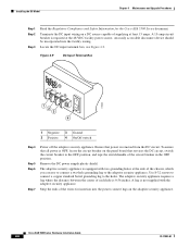
... ends of each hole is required at least 15 amps. To ensure that all power is OFF, locate the circuit breaker on the panel board that power is removed from the DC circuit. Remove the DC power supply plastic shield. Cisco ASA 5500 Series Hardware Installation Guide 4-8 78-17989-01 Figure 4-9 DC-Input Terminal Box + - 119640...
... ends of each hole is required at least 15 amps. To ensure that all power is OFF, locate the circuit breaker on the panel board that power is removed from the DC circuit. Remove the DC power supply plastic shield. Cisco ASA 5500 Series Hardware Installation Guide 4-8 78-17989-01 Figure 4-9 DC-Input Terminal Box + - 119640...
Hardware Installation Guide
Page 43
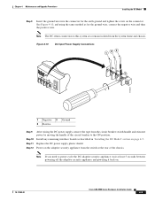
... the ground wire, connect the negative wire and then the positive wire. Replace the DC power supply plastic shield. Install any remaining interface boards as for the earth ground and tighten the screw on . 78-17989-01 Cisco ASA 5500 Series Hardware Installation Guide 4-9 See Figure 4-10, and using the same method as described...
... the ground wire, connect the negative wire and then the positive wire. Replace the DC power supply plastic shield. Install any remaining interface boards as for the earth ground and tighten the screw on . 78-17989-01 Cisco ASA 5500 Series Hardware Installation Guide 4-9 See Figure 4-10, and using the same method as described...
Hardware Installation Guide
Page 71
Numerics 1000 W power supplies power cords (table) 2-5 4GE SSM 4-15, 4-22 A AC-input power cords product numbers (table) 2-5 ASA replacing lithium battery 4-4 AUX port 1-2 C chassis covers removing 4-1 replacing 4-2 circuit breaker for DC unit 2-3 Cisco warranty 2-2 CompactFlash External 1-2, 1-3 Internal 4-10, 4-12 Console port 3-6 CPU 1-5 E electrostatic discharge see ... 4-8 I interface cables 3-4 4GE SSM 3-7 console port 3-6 management port 3-5 SSM 3-9 L LC connector 3-8 LEDs 1-4, 4-14, 4-21 M memory requirements 1-5 MGMT 1-2, 1-3, 3-5 Cisco ASA 5500 Series Hardware Installation Guide IN-1
Numerics 1000 W power supplies power cords (table) 2-5 4GE SSM 4-15, 4-22 A AC-input power cords product numbers (table) 2-5 ASA replacing lithium battery 4-4 AUX port 1-2 C chassis covers removing 4-1 replacing 4-2 circuit breaker for DC unit 2-3 Cisco warranty 2-2 CompactFlash External 1-2, 1-3 Internal 4-10, 4-12 Console port 3-6 CPU 1-5 E electrostatic discharge see ... 4-8 I interface cables 3-4 4GE SSM 3-7 console port 3-6 management port 3-5 SSM 3-9 L LC connector 3-8 LEDs 1-4, 4-14, 4-21 M memory requirements 1-5 MGMT 1-2, 1-3, 3-5 Cisco ASA 5500 Series Hardware Installation Guide IN-1
Hardware Installation Guide
Page 72
Index N Network interfaces 1-2 P panel removing 4-2 power LEDs 1-3, 1-4, 4-14, 4-21 power supplies considerations 2-4 product overview 1-2 R rear panels (figure) 1-4 RJ-45 connector pinouts 1-4 RJ-45 port 3-7 rubber feet attaching 3-3 S safety 2-2 Serial Console port 1-2, 1-3 SFP 3-7, 4-16 site environment 2-4 SSM 3-9, 4-4 4GE SSM connecting 3-7 installing 4-15, 4-22 LEDs 1-3, 4-14 replacing 4-16, 4-23 V ventilation fans 2-7 IN-2 Cisco ASA 5500 Series Hardware Installation Guide W warranty 2-2 78-17989-01
Index N Network interfaces 1-2 P panel removing 4-2 power LEDs 1-3, 1-4, 4-14, 4-21 power supplies considerations 2-4 product overview 1-2 R rear panels (figure) 1-4 RJ-45 connector pinouts 1-4 RJ-45 port 3-7 rubber feet attaching 3-3 S safety 2-2 Serial Console port 1-2, 1-3 SFP 3-7, 4-16 site environment 2-4 SSM 3-9, 4-4 4GE SSM connecting 3-7 installing 4-15, 4-22 LEDs 1-3, 4-14 replacing 4-16, 4-23 V ventilation fans 2-7 IN-2 Cisco ASA 5500 Series Hardware Installation Guide W warranty 2-2 78-17989-01
