
Hardware Installation Guide
Page 18
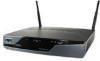
General Descriptions of the Router Models Chapter 1 Product Overview Figure 1-5 Cisco 857 Router Back Panel, with Antenna Installed 122242 SN: XXXNNNNXXXX LAN FE0 FE1 FE2 FE3 Cisco 857W ADSLoPOTS RESET CONSOLE AUX +5,+12 VDC Figure 1-6 Cisco 877 Router Back Panel, with Antennas Installed 127093 LEFT SN: XXXNNNNXXXX LAN FE0 FE1 FE2 FE3 Cisco 877W ADSLoPOTS RESET CONSOLE AUX +5,+12 VDC RIGHT/PRIMARY Cisco 850 Series and Cisco 870 Series Access Routers Hardware Installation Guide 1-4 OL-5331-01
General Descriptions of the Router Models Chapter 1 Product Overview Figure 1-5 Cisco 857 Router Back Panel, with Antenna Installed 122242 SN: XXXNNNNXXXX LAN FE0 FE1 FE2 FE3 Cisco 857W ADSLoPOTS RESET CONSOLE AUX +5,+12 VDC Figure 1-6 Cisco 877 Router Back Panel, with Antennas Installed 127093 LEFT SN: XXXNNNNXXXX LAN FE0 FE1 FE2 FE3 Cisco 877W ADSLoPOTS RESET CONSOLE AUX +5,+12 VDC RIGHT/PRIMARY Cisco 850 Series and Cisco 870 Series Access Routers Hardware Installation Guide 1-4 OL-5331-01

Hardware Installation Guide
Page 48
Typical Installations Figure 4-2 Typical Installation of a Cisco 857 or Cisco 877 Router Chapter 4 Router Cabling Procedures 122238 LEFT SN: XXXNNNNXXXX ETHERNET LAN FE3 4 FE2 3 FE1 2 FE0 1 Cisco 877W ADSLoPOTS RESET CONSOLE AUX +5,+12 VDC RIGHT / PRIMARY 1 2 3 4 5 1X 2X 1X 2X 1 1 Ethernet connection to an external switch 2 Ethernet connection to a PC 3 ADSL-over-POTS connection 4 Console port 5 Power adapter Cisco 850 Series and Cisco 870 Series Access Routers Hardware Installation Guide 4-4 OL-5331-01
Typical Installations Figure 4-2 Typical Installation of a Cisco 857 or Cisco 877 Router Chapter 4 Router Cabling Procedures 122238 LEFT SN: XXXNNNNXXXX ETHERNET LAN FE3 4 FE2 3 FE1 2 FE0 1 Cisco 877W ADSLoPOTS RESET CONSOLE AUX +5,+12 VDC RIGHT / PRIMARY 1 2 3 4 5 1X 2X 1X 2X 1 1 Ethernet connection to an external switch 2 Ethernet connection to a PC 3 ADSL-over-POTS connection 4 Console port 5 Power adapter Cisco 850 Series and Cisco 870 Series Access Routers Hardware Installation Guide 4-4 OL-5331-01
Hardware Installation Guide
Page 60
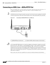
Follow the steps shown after Figure 4-12 to connect an asymmetric digital subscriber line (ADSL) over plain old telephone service (ADSLoPOTS) port on the router 2 End of the primary protection device. If the CD LED is not on, check with regulatory standards such as FCC ...ADSLoPOTS Port This section applies only to an ADSL Line LEFT LAN FE0 FE1 FE2 FE3 Cisco 877W ADSLoPOTS RESET CONSOLE AUX +5,+12 VDC 1 2 RIGHT / PRIMARY 117977 1 ADSLoPOTS port on the router. These standards assume Primary Protection devices protect the Customer Premise Equipment (CPE). These devices are...
Follow the steps shown after Figure 4-12 to connect an asymmetric digital subscriber line (ADSL) over plain old telephone service (ADSLoPOTS) port on the router 2 End of the primary protection device. If the CD LED is not on, check with regulatory standards such as FCC ...ADSLoPOTS Port This section applies only to an ADSL Line LEFT LAN FE0 FE1 FE2 FE3 Cisco 877W ADSLoPOTS RESET CONSOLE AUX +5,+12 VDC 1 2 RIGHT / PRIMARY 117977 1 ADSLoPOTS port on the router. These standards assume Primary Protection devices protect the Customer Premise Equipment (CPE). These devices are...
