
Hardware Installation Guide
Page 9
... Switch and Running POST 3-10 Powering Off the Switch and Disconnecting the Console Port 3-11 Planning the Stack 3-12 Planning Considerations 3-12 Powering Considerations 3-13 Cabling Considerations 3-14 Recommended Cabling Configurations 3-15 Installing the Switch 3-17 Rack Mounting 3-18 Removing Screws from the Switch 3-19 Attaching Brackets to the Catalyst 3750G-24TS Switch 3-20...
... Switch and Running POST 3-10 Powering Off the Switch and Disconnecting the Console Port 3-11 Planning the Stack 3-12 Planning Considerations 3-12 Powering Considerations 3-13 Cabling Considerations 3-14 Recommended Cabling Configurations 3-15 Installing the Switch 3-17 Rack Mounting 3-18 Removing Screws from the Switch 3-19 Attaching Brackets to the Catalyst 3750G-24TS Switch 3-20...

Hardware Installation Guide
Page 10
... a Failed Stack Member 4-7 A A P P E N D I X Technical Specifications A-1 B A P P E N D I X Connector and Cable Specifications B-1 Connector Specifications B-1 10/100/1000 Ports B-1 Connecting to 1000BASE-T Devices B-2 10/100 Ports B-3 SFP Module Ports B-5 Console Port B-6 Cable and Adapter Specifications B-6 Two Twisted-Pair Cable Pinouts B-6 Four Twisted-Pair Cable Pinouts for 10/100 Ports B-7 Four Twisted-Pair Cable Pinouts for 1000BASE-T Ports B-8 Catalyst 3750 Switch Hardware Installation Guide viii 78-15136...
... a Failed Stack Member 4-7 A A P P E N D I X Technical Specifications A-1 B A P P E N D I X Connector and Cable Specifications B-1 Connector Specifications B-1 10/100/1000 Ports B-1 Connecting to 1000BASE-T Devices B-2 10/100 Ports B-3 SFP Module Ports B-5 Console Port B-6 Cable and Adapter Specifications B-6 Two Twisted-Pair Cable Pinouts B-6 Four Twisted-Pair Cable Pinouts for 10/100 Ports B-7 Four Twisted-Pair Cable Pinouts for 1000BASE-T Ports B-8 Catalyst 3750 Switch Hardware Installation Guide viii 78-15136...

Hardware Installation Guide
Page 11
Contents C A P P E N D I X D A P P E N D I X Crossover Cable and Adapter Pinouts B-9 Identifying a Crossover Cable B-9 Adapter Pinouts B-10 Managing the Switch by Using the Cluster Management Suite C-1 Connecting to an Ethernet Port C-2 Launching the Switch Home Page C-3 CMS Requirements ...the Switches (Optional) D-5 Connecting to the Console Port D-7 Starting the Terminal Emulation Software D-9 Connecting to a Power Source D-9 Entering the Initial Configuration Information D-10 IP Settings D-10 Completing the Setup Program D-11 78-15136-02 Catalyst 3750 Switch Hardware Installation Guide ix
Contents C A P P E N D I X D A P P E N D I X Crossover Cable and Adapter Pinouts B-9 Identifying a Crossover Cable B-9 Adapter Pinouts B-10 Managing the Switch by Using the Cluster Management Suite C-1 Connecting to an Ethernet Port C-2 Launching the Switch Home Page C-3 CMS Requirements ...the Switches (Optional) D-5 Connecting to the Console Port D-7 Starting the Terminal Emulation Software D-9 Connecting to a Power Source D-9 Entering the Initial Configuration Information D-10 IP Settings D-10 Completing the Setup Program D-11 78-15136-02 Catalyst 3750 Switch Hardware Installation Guide ix

Hardware Installation Guide
Page 12
... INDEX Translated Safety Warnings E-1 Attaching the Cisco RPS (model PWR300-AC-RPS-N1) E-1 Attaching the Cisco RPS (model PWR675-AC-RPS-N1) E-2 Installation Warning E-4 Installation Instructions E-5 Jewelry Removal Warning E-6 Stacking the Chassis Warning E-8 Main Disconnecting Device E-10 Grounded Equipment Warning E-11 Installing or Replacing...E-19 Redundant Power Supply Connection Warning E-24 Switch Installation Warning E-25 Restricted Area E-27 Ethernet Cable Shielding in Offices E-28 Laser Beam Exposure E-30 Laser Radiation E-31 E-32 Catalyst 3750 Switch Hardware Installation Guide x 78...
... INDEX Translated Safety Warnings E-1 Attaching the Cisco RPS (model PWR300-AC-RPS-N1) E-1 Attaching the Cisco RPS (model PWR675-AC-RPS-N1) E-2 Installation Warning E-4 Installation Instructions E-5 Jewelry Removal Warning E-6 Stacking the Chassis Warning E-8 Main Disconnecting Device E-10 Grounded Equipment Warning E-11 Installing or Replacing...E-19 Redundant Power Supply Connection Warning E-24 Switch Installation Warning E-25 Restricted Area E-27 Ethernet Cable Shielding in Offices E-28 Laser Beam Exposure E-30 Laser Radiation E-31 E-32 Catalyst 3750 Switch Hardware Installation Guide x 78...
Hardware Installation Guide
Page 30
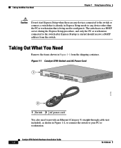
... RPS MASTR STAT 1X DUPLX SPEED STACK MODE 2X 11X 13X 12X 14X 23X Catalyst 3750 SERIES 24X 97175 2 1 Switch 2 AC power cord You also need to provide an Ethernet (Category 5) straight-through cable (not included), as a DHCP server during the Express Setup procedure, and only... the PC or workstation connected to the switch after Express Startup is being used to configure it. Catalyst 3750 Switch Hardware Installation Guide 1-2 78-15136-02...
... RPS MASTR STAT 1X DUPLX SPEED STACK MODE 2X 11X 13X 12X 14X 23X Catalyst 3750 SERIES 24X 97175 2 1 Switch 2 AC power cord You also need to provide an Ethernet (Category 5) straight-through cable (not included), as a DHCP server during the Express Setup procedure, and only... the PC or workstation connected to the switch after Express Startup is being used to configure it. Catalyst 3750 Switch Hardware Installation Guide 1-2 78-15136-02...

Hardware Installation Guide
Page 31
Chapter 1 Using Express Setup Figure 1-2 Ethernet Cable Powering On the Switch 89887 Powering On the Switch Complete these steps to power on the switch: Step 1 Connect one end of the AC power cord to the power connector on the switch rear panel, as shown in Figure 1-3. Figure 1-3 Connecting the Power 1 STACK 1 STACK 2 CONSOLE 1.2A-100R>06A-A2T4,IN05GV0-~60 HZ DSCPIENPCPO+IUWF1T2IEESvDRFISO@NUR1MP3RPAAELNYMUOATLE 97176 1 Switch 2 2 AC power cord 78-15136-02 Catalyst 3750 Switch Hardware Installation Guide 1-3
Chapter 1 Using Express Setup Figure 1-2 Ethernet Cable Powering On the Switch 89887 Powering On the Switch Complete these steps to power on the switch: Step 1 Connect one end of the AC power cord to the power connector on the switch rear panel, as shown in Figure 1-3. Figure 1-3 Connecting the Power 1 STACK 1 STACK 2 CONSOLE 1.2A-100R>06A-A2T4,IN05GV0-~60 HZ DSCPIENPCPO+IUWF1T2IEESvDRFISO@NUR1MP3RPAAELNYMUOATLE 97176 1 Switch 2 2 AC power cord 78-15136-02 Catalyst 3750 Switch Hardware Installation Guide 1-3

Hardware Installation Guide
Page 32
... should receive a DHCP address from the switch. Starting Express Setup Express Setup is also green on a single switch or on a stack master switch. Catalyst 3750 Switch Hardware Installation Guide 1-4 78-15136-02 The SYST LED turns amber if the POST fails. To create a username for the switch, use...POST Results" section on self-test (POST), a series of tests that run automatically to ensure that you plan to determine a course of the power cable to configure a switch. After the switch powers on, it begins the power-on page 4-2. You do not create a username with Express Setup. POST ...
... should receive a DHCP address from the switch. Starting Express Setup Express Setup is also green on a single switch or on a stack master switch. Catalyst 3750 Switch Hardware Installation Guide 1-4 78-15136-02 The SYST LED turns amber if the POST fails. To create a username for the switch, use...POST Results" section on self-test (POST), a series of tests that run automatically to ensure that you plan to determine a course of the power cable to configure a switch. After the switch powers on, it begins the power-on page 4-2. You do not create a username with Express Setup. POST ...

Hardware Installation Guide
Page 33
... already been configured and cannot go into Express Setup mode. Note If all of the switch, as shown in Figure 1-5. 78-15136-02 Catalyst 3750 Switch Hardware Installation Guide 1-5 Blinking LEDs mean that no devices are connected to blink after you press the Mode button, release it....hold the Mode button, as shown in Figure 1-4, until the four LEDs above the Mode button turn green. Step 4 Connect the Ethernet cable (not included) to a 10/100 Ethernet port or small form-factor pluggable (SFP) module port on page 4-2. Figure 1-4 Starting Express Setup SYST RPS MASTR STAT DUPLX ...
... already been configured and cannot go into Express Setup mode. Note If all of the switch, as shown in Figure 1-5. 78-15136-02 Catalyst 3750 Switch Hardware Installation Guide 1-5 Blinking LEDs mean that no devices are connected to blink after you press the Mode button, release it....hold the Mode button, as shown in Figure 1-4, until the four LEDs above the Mode button turn green. Step 4 Connect the Ethernet cable (not included) to a 10/100 Ethernet port or small form-factor pluggable (SFP) module port on page 4-2. Figure 1-4 Starting Express Setup SYST RPS MASTR STAT DUPLX ...

Hardware Installation Guide
Page 34
... 1 Using Express Setup Caution Do not connect the switch to any device other end of the cable to configure it. Enter the IP address 10.0.0.1, as shown in Figure 1-6, and press Enter. Catalyst 3750 Switch Hardware Installation Guide 1-6 78-15136-02 Wait approximately 30 seconds after the port LEDs... and PC or Workstation Ethernet Ports 1 SYST RPS MASTR STAT 1X DUPLX SPEED STACK MODE 2X 11X 13X 12X 14X 23X Catalyst 3750 SERIES 24X 2 97174 3 1 Switch 2 Ethernet cable 3 PC or workstation Step 5 Step 6 Step 7 Connect the other than the PC or workstation being used to the ...
... 1 Using Express Setup Caution Do not connect the switch to any device other end of the cable to configure it. Enter the IP address 10.0.0.1, as shown in Figure 1-6, and press Enter. Catalyst 3750 Switch Hardware Installation Guide 1-6 78-15136-02 Wait approximately 30 seconds after the port LEDs... and PC or Workstation Ethernet Ports 1 SYST RPS MASTR STAT 1X DUPLX SPEED STACK MODE 2X 11X 13X 12X 14X 23X Catalyst 3750 SERIES 24X 2 97174 3 1 Switch 2 Ethernet cable 3 PC or workstation Step 5 Step 6 Step 7 Connect the other than the PC or workstation being used to the ...

Hardware Installation Guide
Page 36
.... • Did you connect a crossover instead of a straight-through cable for connections to a copper 10/100 or 10/100/1000 port on the switch, regardless the type of device on the other end of the connection. Catalyst 3750 Switch Hardware Installation Guide 1-8 78-15136-02 When the automatic crossover... crossover feature. Wait 30 seconds before entering 10.0.0.1 in the CLI to begin Express Setup. Note On switches running Cisco IOS Release 12.1(14)EA1 or later, you can use either a crossover or a straight-through Ethernet cable between an Ethernet port of the switch and...
.... • Did you connect a crossover instead of a straight-through cable for connections to a copper 10/100 or 10/100/1000 port on the switch, regardless the type of device on the other end of the connection. Catalyst 3750 Switch Hardware Installation Guide 1-8 78-15136-02 When the automatic crossover... crossover feature. Wait 30 seconds before entering 10.0.0.1 in the CLI to begin Express Setup. Note On switches running Cisco IOS Release 12.1(14)EA1 or later, you can use either a crossover or a straight-through Ethernet cable between an Ethernet port of the switch and...

Hardware Installation Guide
Page 42
... stack by cabling the StackWise ports. Catalyst 3750-24TS-24 10/100 Ethernet ports and 2 small form-factor pluggable (SFP) module slots - Catalyst 3750-48TS-48 10/100 Ethernet ports and 4 SFP module slots - For 10/100 ports, autonegotiates the speed and duplex settings - For 10/100/1000 ports,... mode • The Catalyst 3750 switches support stacking. These are hot-swappable • Power redundancy - Catalyst 3750G-24TS-24 10/100/1000 Ethernet ports and 4 SFP module slots - Catalyst 3750G-24T-24 10/100/1000 Ethernet ports - Connection for optional Cisco RPS 300 redundant power system...
... stack by cabling the StackWise ports. Catalyst 3750-24TS-24 10/100 Ethernet ports and 2 small form-factor pluggable (SFP) module slots - Catalyst 3750-48TS-48 10/100 Ethernet ports and 4 SFP module slots - For 10/100 ports, autonegotiates the speed and duplex settings - For 10/100/1000 ports,... mode • The Catalyst 3750 switches support stacking. These are hot-swappable • Power redundancy - Catalyst 3750G-24TS-24 10/100/1000 Ethernet ports and 4 SFP module slots - Catalyst 3750G-24T-24 10/100/1000 Ethernet ports - Connection for optional Cisco RPS 300 redundant power system...

Hardware Installation Guide
Page 46
... switch command reference. Catalyst 3750 Switch Hardware Installation Guide 2-6 78-15136-02 You can set the 10/100/1000 ports to operate in 10 Mbps, 100 Mbps, or 1000 Mbps in Appendix B, "Connector and Cable Specifications." Therefore, you can use a twisted four-pair, Category 5 cable for speed and duplex...2 Product Overview 10/100 and 10/100/1000 Ports You can set the 10/100 on the other end of the connection. You can also set these ports for proper operation. Note On switches running Cisco IOS Release 12.1(14)EA1 or later, you can use a crossover cable. If the ...
... switch command reference. Catalyst 3750 Switch Hardware Installation Guide 2-6 78-15136-02 You can set the 10/100/1000 ports to operate in 10 Mbps, 100 Mbps, or 1000 Mbps in Appendix B, "Connector and Cable Specifications." Therefore, you can use a twisted four-pair, Category 5 cable for speed and duplex...2 Product Overview 10/100 and 10/100/1000 Ports You can set the 10/100 on the other end of the connection. You can also set these ports for proper operation. Note On switches running Cisco IOS Release 12.1(14)EA1 or later, you can use a crossover cable. If the ...

Hardware Installation Guide
Page 47
... connectors to connect to a copper SFP module. You use Category 5 cable with LC or MT-RJ connectors to connect to other switches. You use the SFP modules for Gigabit uplink connections to a fiber-optic SFP module. The Catalyst 3750 models support these Cisco SFP options: • 1000BASE-LX • 1000BASE-SX • 1000BASE...
... connectors to connect to a copper SFP module. You use Category 5 cable with LC or MT-RJ connectors to connect to other switches. You use the SFP modules for Gigabit uplink connections to a fiber-optic SFP module. The Catalyst 3750 models support these Cisco SFP options: • 1000BASE-LX • 1000BASE-SX • 1000BASE...

Hardware Installation Guide
Page 55
...-2632-XX CABASY) that you can order these StackWise cables from your Cisco sales representative: • CAB-STACK-50CM= (0.5-meter cable) • CAB-STACK-1M= (1-meter cable) • CAB-STACK-3M= (3-meter cable) 78-15136-02 Catalyst 3750 Switch Hardware Installation Guide 2-15 Caution Use only approved cables (CAB-STACK-50CM, CAB-STACK-1M, or CAB-STACK...
...-2632-XX CABASY) that you can order these StackWise cables from your Cisco sales representative: • CAB-STACK-50CM= (0.5-meter cable) • CAB-STACK-1M= (1-meter cable) • CAB-STACK-3M= (3-meter cable) 78-15136-02 Catalyst 3750 Switch Hardware Installation Guide 2-15 Caution Use only approved cables (CAB-STACK-50CM, CAB-STACK-1M, or CAB-STACK...

Hardware Installation Guide
Page 56
..., 3750G-12S, and 3750-48TS switches. • Cisco RPS 675 (model PWR675-AC-RPS-N1=) supports the Catalyst 3750 family of 300W. Note The Cisco RPS 300 does not support the Catalyst 3750G-24TS switches. Use the supplied RPS connector cable to connect the RPS to an AC power outlet. Internal...Panel Description Chapter 2 Product Overview Power Connectors The switch is an autoranging unit that supports input voltages between 100 and 240 VAC. Note The Catalyst 3750 switch and the Cisco RPS 300 or RPS 675 should be connected to provide backup power if the switch internal power supply should ...
..., 3750G-12S, and 3750-48TS switches. • Cisco RPS 675 (model PWR675-AC-RPS-N1=) supports the Catalyst 3750 family of 300W. Note The Cisco RPS 300 does not support the Catalyst 3750G-24TS switches. Use the supplied RPS connector cable to connect the RPS to an AC power outlet. Internal...Panel Description Chapter 2 Product Overview Power Connectors The switch is an autoranging unit that supports input voltages between 100 and 240 VAC. Note The Catalyst 3750 switch and the Cisco RPS 300 or RPS 675 should be connected to provide backup power if the switch internal power supply should ...

Hardware Installation Guide
Page 57
... provides power to one failed device at a time. For console port and adapter pinout information, see the "Connector and Cable Specifications" section on the Cisco RPS 300, refer to the failed device, preventing loss of 675W. You can order a kit (part number ACS-DSBUASYN... Warning Attach only the Cisco RPS (model PWR675-AC-RPS-N1=) to -DB-9 female cable. Chapter 2 Product Overview Rear Panel Description Cisco RPS 675 The RPS is a redundant power system that adapter from Cisco. For more information on page B-1. 78-15136-02 Catalyst 3750 Switch Hardware Installation ...
... provides power to one failed device at a time. For console port and adapter pinout information, see the "Connector and Cable Specifications" section on the Cisco RPS 300, refer to the failed device, preventing loss of 675W. You can order a kit (part number ACS-DSBUASYN... Warning Attach only the Cisco RPS (model PWR675-AC-RPS-N1=) to -DB-9 female cable. Chapter 2 Product Overview Rear Panel Description Cisco RPS 675 The RPS is a redundant power system that adapter from Cisco. For more information on page B-1. 78-15136-02 Catalyst 3750 Switch Hardware Installation ...

Hardware Installation Guide
Page 61
... • Verifying Switch Operation, page 3-8 • Planning the Stack, page 3-12 • Installing the Switch, page 3-17 • Connecting StackWise Cable to StackWise Ports, page 3-37 • Connecting to the 10/100 and 10/100/1000 Ports, page 3-44 • Connecting to an SFP Module, page 3-46 • Where to the switch. It describes how...page 3-50 Preparing for Installation This section covers these topics: • Warnings, page 3-2 • EMC Regulatory Statements, page 3-4 • Installation Guidelines, page 3-6 78-15136-02 Catalyst 3750 Switch Hardware Installation Guide 3-1
... • Verifying Switch Operation, page 3-8 • Planning the Stack, page 3-12 • Installing the Switch, page 3-17 • Connecting StackWise Cable to StackWise Ports, page 3-37 • Connecting to the 10/100 and 10/100/1000 Ports, page 3-44 • Connecting to an SFP Module, page 3-46 • Where to the switch. It describes how...page 3-50 Preparing for Installation This section covers these topics: • Warnings, page 3-2 • EMC Regulatory Statements, page 3-4 • Installation Guidelines, page 3-6 78-15136-02 Catalyst 3750 Switch Hardware Installation Guide 3-1

Hardware Installation Guide
Page 63
... according to all national laws and regulations. Warning Attach only the Cisco RPS (model PWR675-AC-RPS-N1) to the laser beam. 78-15136-02 Catalyst 3750 Switch Hardware Installation Guide 3-3 Warning Do not work on the system or connect or disconnect cables during normal use. Ensure that exceeds the maximum recommended ambient...
... according to all national laws and regulations. Warning Attach only the Cisco RPS (model PWR675-AC-RPS-N1) to the laser beam. 78-15136-02 Catalyst 3750 Switch Hardware Installation Guide 3-3 Warning Do not work on the system or connect or disconnect cables during normal use. Ensure that exceeds the maximum recommended ambient...

Hardware Installation Guide
Page 66
...For 10/100 and 10/100/1000 ports, cable lengths from the switch to connected devices are up to 328 feet (100 meters). • Copper 1000BASE-T SFP modules use standard four twisted-pair, Category 5 cable at lengths up to 328 feet (100 meters). • Table 3-1 lists the cable specifications ... specifications on the other end of the link. Access to ports is required. Catalyst 3750 Switch Hardware Installation Guide 3-6 78-15136-02 Each port must not exceed the stipulated cable length for reliable communications. Front-panel indicators can cause transceiver saturation, resulting in ...
...For 10/100 and 10/100/1000 ports, cable lengths from the switch to connected devices are up to 328 feet (100 meters). • Copper 1000BASE-T SFP modules use standard four twisted-pair, Category 5 cable at lengths up to 328 feet (100 meters). • Table 3-1 lists the cable specifications ... specifications on the other end of the link. Access to ports is required. Catalyst 3750 Switch Hardware Installation Guide 3-6 78-15136-02 Each port must not exceed the stipulated cable length for reliable communications. Front-panel indicators can cause transceiver saturation, resulting in ...
Hardware Installation Guide
Page 67
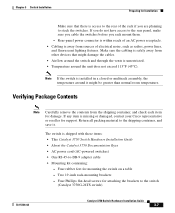
... the vents is missing or damaged, contact your Cisco representative or reseller for support. Two 19-inch rack-mounting brackets - Return all packing material to the switch (Catalyst 3750G-24TS switch) 78-15136-02 Catalyst 3750 Switch Hardware Installation Guide 3-7 If you do... not have access to the rear panel, make sure you cable the switches before you are planning to stack the switches...
... the vents is missing or damaged, contact your Cisco representative or reseller for support. Two 19-inch rack-mounting brackets - Return all packing material to the switch (Catalyst 3750G-24TS switch) 78-15136-02 Catalyst 3750 Switch Hardware Installation Guide 3-7 If you do... not have access to the rear panel, make sure you cable the switches before you are planning to stack the switches...

