
Installation Guide
Page 6
...Up the Switch 2-1 Preparing for Using the Switch 1-25 Small- Contents 2 C H A P T E R LEDs 1-11 System LED 1-14 RPS LED 1-15 Port LEDs and Modes 1-16 Rear-Panel Description 1-21 Power Connectors 1-22 Internal Power Supply Connector 1-23 Cisco RPS ...Connector 1-23 Console Port 1-24 Management Options 1-24 Network Configuration Examples 1-25 Design Concepts for Installation 2-2 Warnings 2-2 EMC Regulatory Statements 2-5 U.S.A. 2-5 Taiwan 2-5 Japan 2-6 Korea 2-6 Hungary 2-7 Installation Guidelines 2-7 Verifying Package Contents 2-8 Catalyst 3500 Series XL Hardware Installation...
...Up the Switch 2-1 Preparing for Using the Switch 1-25 Small- Contents 2 C H A P T E R LEDs 1-11 System LED 1-14 RPS LED 1-15 Port LEDs and Modes 1-16 Rear-Panel Description 1-21 Power Connectors 1-22 Internal Power Supply Connector 1-23 Cisco RPS ...Connector 1-23 Console Port 1-24 Management Options 1-24 Network Configuration Examples 1-25 Design Concepts for Installation 2-2 Warnings 2-2 EMC Regulatory Statements 2-5 U.S.A. 2-5 Taiwan 2-5 Japan 2-6 Korea 2-6 Hungary 2-7 Installation Guidelines 2-7 Verifying Package Contents 2-8 Catalyst 3500 Series XL Hardware Installation...

Installation Guide
Page 7
...Rack 2-13 Attaching the Optional Cable Guide 2-13 Installing the Switch on a Wall 2-15 Attaching the Brackets to the Switch 2-15 Attaching the Switch to a Wall 2-16 Installing the Switch on a Table or Shelf 2-17 Powering On the Switch and Running POST 2-17 Connecting to the 10/100 Ports... 1000BaseX GBIC Module Port 2-21 Connecting to a GigaStack GBIC Module Port 2-22 Connecting a PC or Terminal to the Console Port 2-23 Assigning Switch Information 2-24 Using the Setup Program 2-25 Using BOOTP 2-29 Default Configuration Settings 2-29 Where to Go Next 2-31 Troubleshooting 3-1 Understanding POST ...
...Rack 2-13 Attaching the Optional Cable Guide 2-13 Installing the Switch on a Wall 2-15 Attaching the Brackets to the Switch 2-15 Attaching the Switch to a Wall 2-16 Installing the Switch on a Table or Shelf 2-17 Powering On the Switch and Running POST 2-17 Connecting to the 10/100 Ports... 1000BaseX GBIC Module Port 2-21 Connecting to a GigaStack GBIC Module Port 2-22 Connecting a PC or Terminal to the Console Port 2-23 Assigning Switch Information 2-24 Using the Setup Program 2-25 Using BOOTP 2-29 Default Configuration Settings 2-29 Where to Go Next 2-31 Troubleshooting 3-1 Understanding POST ...

Installation Guide
Page 9
INDEX Grounded Equipment Warning C-23 Supply Circuit Warning C-24 No On/Off Switch Warning C-25 Power Supply Warning C-27 Work During Lightning Activity Warning C-30 Product Disposal Warning C-31 Chassis Warning-Rack-Mounting and Servicing C-33 Chassis Power Connection Warning C-38 Shock Hazard from Interconnections Warning C-41 Contents 78-6456-03 Catalyst 3500 Series XL Hardware Installation Guide ix
INDEX Grounded Equipment Warning C-23 Supply Circuit Warning C-24 No On/Off Switch Warning C-25 Power Supply Warning C-27 Work During Lightning Activity Warning C-30 Product Disposal Warning C-31 Chassis Warning-Rack-Mounting and Servicing C-33 Chassis Power Connection Warning C-38 Shock Hazard from Interconnections Warning C-41 Contents 78-6456-03 Catalyst 3500 Series XL Hardware Installation Guide ix
Installation Guide
Page 11
... Audience This guide is for the networking or computer technician responsible for installing and configuring a Catalyst 3500 series XL switch. It describes the physical and performance characteristics of the switches in the series, explains how to install a switch and set up its initial configuration, provides troubleshooting information, and describes how to assign IP information to...
... Audience This guide is for the networking or computer technician responsible for installing and configuring a Catalyst 3500 series XL switch. It describes the physical and performance characteristics of the switches in the series, explains how to install a switch and set up its initial configuration, provides troubleshooting information, and describes how to assign IP information to...

Installation Guide
Page 12
It describes the switch ports, the standards they support, and the switch LEDs. Chapter 3, "Troubleshooting," describes how to identify and resolve some of the warnings in italic. Appendix C, "Translated Safety Warnings," contains ... (< >). Appendix B, "Connector and Cable Specifications," describes the connectors, cables, and adapters that might arise when you supply values are installing the switch. Catalyst 3500 Series XL Hardware Installation Guide xii 78-6456-04 Appendix A, "Technical Specifications," lists the physical and environmental specifications for installing...
It describes the switch ports, the standards they support, and the switch LEDs. Chapter 3, "Troubleshooting," describes how to identify and resolve some of the warnings in italic. Appendix C, "Translated Safety Warnings," contains ... (< >). Appendix B, "Connector and Cable Specifications," describes the connectors, cables, and adapters that might arise when you supply values are installing the switch. Catalyst 3500 Series XL Hardware Installation Guide xii 78-6456-04 Appendix A, "Technical Specifications," lists the physical and environmental specifications for installing...
Installation Guide
Page 18
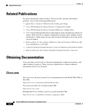
... sections explain how to display switch information. Online help also provides detailed information about Catalyst 3500 series XL switches and related products, refer to the following publications: • Quick Start: Catalyst 3500 Series XL Cabling and Setup • Cisco IOS Desktop Switching Software Configuration Guide • Cisco IOS Desktop Switching Command Reference (online only) • Cisco Cluster Management Suite online help...
... sections explain how to display switch information. Online help also provides detailed information about Catalyst 3500 series XL switches and related products, refer to the following publications: • Quick Start: Catalyst 3500 Series XL Cabling and Setup • Cisco IOS Desktop Switching Software Configuration Guide • Cisco IOS Desktop Switching Command Reference (online only) • Cisco Cluster Management Suite online help...

Installation Guide
Page 25
A feature specific to the Catalyst 3524-PWR XL switch is its ability to provide inline power to Cisco IP Phones. (Phone adapters are stackable 10/100 Ethernet switches to the Catalyst 3524-PWR XL 10/100 switch ports.) Figure 1-1 shows the switch models in different network topologies Features The Catalyst 3500 series XL switches-also referred to as Catalyst 3500 XL switches-are not required when...
A feature specific to the Catalyst 3524-PWR XL switch is its ability to provide inline power to Cisco IP Phones. (Phone adapters are stackable 10/100 Ethernet switches to the Catalyst 3524-PWR XL 10/100 switch ports.) Figure 1-1 shows the switch models in different network topologies Features The Catalyst 3500 series XL switches-also referred to as Catalyst 3500 XL switches-are not required when...

Installation Guide
Page 26
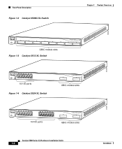
... 44 45 46 47 48 STATUS UTIL 47X 1 DUPLEX SPEED 2X MODE 16X 18X 32X 34X 2 48X 30210 Catalyst 3500 Series XL Hardware Installation Guide 1-2 78-6456-04 Features Chapter 1 Product Overview Figure 1-1 Catalyst 3500 Series XL Switches Switch Description WS-C3508G-XL 8 GBIC1-based gigabit module slots 1 SYSTEM 2 3 RPS 4 5 MODE STATUS UTIL DUPLX SPEED 6 7 8 WS-C3512...
... 44 45 46 47 48 STATUS UTIL 47X 1 DUPLEX SPEED 2X MODE 16X 18X 32X 34X 2 48X 30210 Catalyst 3500 Series XL Hardware Installation Guide 1-2 78-6456-04 Features Chapter 1 Product Overview Figure 1-1 Catalyst 3500 Series XL Switches Switch Description WS-C3508G-XL 8 GBIC1-based gigabit module slots 1 SYSTEM 2 3 RPS 4 5 MODE STATUS UTIL DUPLX SPEED 6 7 8 WS-C3512...

Installation Guide
Page 27
... • Broadcast storm control to the switch 78-6456-04 Catalyst 3500 Series XL Hardware Installation Guide 1-3 Chapter 1 Product Overview Features Table 1-1 Catalyst 3508G XL Features Feature Description Performance and • 8 GBIC-based 1000BaseX Gigabit Ethernet slots Configuration • Support for up to four 1000BaseZX GBICs with the Catalyst 3508G XL switch) Management • Cisco IOS command-line interface (CLI) through...
... • Broadcast storm control to the switch 78-6456-04 Catalyst 3500 Series XL Hardware Installation Guide 1-3 Chapter 1 Product Overview Features Table 1-1 Catalyst 3508G XL Features Feature Description Performance and • 8 GBIC-based 1000BaseX Gigabit Ethernet slots Configuration • Support for up to four 1000BaseZX GBICs with the Catalyst 3508G XL switch) Management • Cisco IOS command-line interface (CLI) through...

Installation Guide
Page 28
Features Chapter 1 Product Overview Table 1-2 Catalyst 3512, 3524, 3524-PWR, and 3548 XL Features Feature Performance and Configuration Description • Autonegotiation of speed and duplex operation on 10/100 Ethernet ports • 12,... control to prevent performance degradation from broadcast storms • SPAN port monitoring on any port • Support for command switch redundancy • Support for Cisco GBIC modules - GigaStack GBIC - 1000BaseSX GBIC module - 1000BaseLX/LH GBIC module - 1000BaseZX GBIC module Catalyst 3500 Series XL Hardware Installation Guide 1-4 78-6456-04
Features Chapter 1 Product Overview Table 1-2 Catalyst 3512, 3524, 3524-PWR, and 3548 XL Features Feature Performance and Configuration Description • Autonegotiation of speed and duplex operation on 10/100 Ethernet ports • 12,... control to prevent performance degradation from broadcast storms • SPAN port monitoring on any port • Support for command switch redundancy • Support for Cisco GBIC modules - GigaStack GBIC - 1000BaseSX GBIC module - 1000BaseLX/LH GBIC module - 1000BaseZX GBIC module Catalyst 3500 Series XL Hardware Installation Guide 1-4 78-6456-04

Installation Guide
Page 29
... the Catalyst 3512, 3524, and 3548 XL switches • Connection for optional Cisco RPS 300 that operates on AC input and supplies DC output to the Catalyst 3524-PWR XL switch Inline Power (Catalyst 3524-PWR XL switch only) • Ability to provide inline power for Cisco IP... described in this section. 78-6456-04 Catalyst 3500 Series XL Hardware Installation Guide 1-5 The front panel of the Catalyst 3512, 3524, 3524-PWR and 3548 XL switches (Figure 1-3, Figure 1-4, Figure 1-5, and Figure 1-6) have a set of the Catalyst 3508G XL switch (Figure 1-2) has eight 1000BaseX GBIC module ...
... the Catalyst 3512, 3524, and 3548 XL switches • Connection for optional Cisco RPS 300 that operates on AC input and supplies DC output to the Catalyst 3524-PWR XL switch Inline Power (Catalyst 3524-PWR XL switch only) • Ability to provide inline power for Cisco IP... described in this section. 78-6456-04 Catalyst 3500 Series XL Hardware Installation Guide 1-5 The front panel of the Catalyst 3512, 3524, 3524-PWR and 3548 XL switches (Figure 1-3, Figure 1-4, Figure 1-5, and Figure 1-6) have a set of the Catalyst 3508G XL switch (Figure 1-2) has eight 1000BaseX GBIC module ...
Installation Guide
Page 30
Front-Panel Description Figure 1-2 Catalyst 3508G XL Switch Chapter 1 Product Overview 18966 1 SYSTEM RPS MODE STATUS UTIL DUPLX SPEED 2 3 4 5 6 7 8 GBIC module slots Figure 1-3 Catalyst 3512 XL Switch 12 1X 34 56 78 SYSTEM MODE RPS 2X STATUS UTIL DUPLX SPEED 9 10 11 12 11X 12X 10/100 ports Figure 1-4 Catalyst 3524 XL Switch 1 2 GBIC module slots 12 1X 34 56 78...
Front-Panel Description Figure 1-2 Catalyst 3508G XL Switch Chapter 1 Product Overview 18966 1 SYSTEM RPS MODE STATUS UTIL DUPLX SPEED 2 3 4 5 6 7 8 GBIC module slots Figure 1-3 Catalyst 3512 XL Switch 12 1X 34 56 78 SYSTEM MODE RPS 2X STATUS UTIL DUPLX SPEED 9 10 11 12 11X 12X 10/100 ports Figure 1-4 Catalyst 3524 XL Switch 1 2 GBIC module slots 12 1X 34 56 78...

Installation Guide
Page 31
... Ports The 10/100 ports on . The 10/100 switch ports can connect, up to any compatible network device: • 10BaseT-compatible devices such as workstations, Cisco IP Phones, and hubs through standard RJ-45 connectors and Category 3, 4, or 5 cabling 78-6456-04 Catalyst 3500 Series XL Hardware Installation Guide 1-7 For example, in Figure 1-3, Figure...
... Ports The 10/100 ports on . The 10/100 switch ports can connect, up to any compatible network device: • 10BaseT-compatible devices such as workstations, Cisco IP Phones, and hubs through standard RJ-45 connectors and Category 3, 4, or 5 cabling 78-6456-04 Catalyst 3500 Series XL Hardware Installation Guide 1-7 For example, in Figure 1-3, Figure...

Installation Guide
Page 32
..., the switch port negotiates the best connection (that is, the fastest line speed that the cable is a straight-through standard RJ-45 connectors and Category 5 cabling Note Category 5 cable is connected. The 10/100 ports on a port, the port Catalyst 3500 Series XL Hardware Installation...-port basis, you select the Auto setting for inline power on the Catalyst 3512, 3524, 3524-PWR, and 3548 XL switches provide protocol support for 100BaseTX traffic. When set to the Cisco IOS Desktop Switching Software Configuration Guide for each 10/100 port: Auto and Never. Front-...
..., the switch port negotiates the best connection (that is, the fastest line speed that the cable is a straight-through standard RJ-45 connectors and Category 5 cabling Note Category 5 cable is connected. The 10/100 ports on a port, the port Catalyst 3500 Series XL Hardware Installation...-port basis, you select the Auto setting for inline power on the Catalyst 3512, 3524, 3524-PWR, and 3548 XL switches provide protocol support for 100BaseTX traffic. When set to the Cisco IOS Desktop Switching Software Configuration Guide for each 10/100 port: Auto and Never. Front-...

Installation Guide
Page 33
.... However, when you can connect the Cisco IP Phone to a Catalyst 3524-PWR XL 10/100 port and to an AC power source for creating a 1-Gbps stack configuration of up to eight GBICs in the Catalyst 3508G XL switch. For information about Cisco IP Phones, refer to the documentation that... came with the switch. Refer to the documentation that came with your Cisco IP Phone. Note GBIC modules are not factory-installed on these switches, but you select the Never...
.... However, when you can connect the Cisco IP Phone to a Catalyst 3524-PWR XL 10/100 port and to an AC power source for creating a 1-Gbps stack configuration of up to eight GBICs in the Catalyst 3508G XL switch. For information about Cisco IP Phones, refer to the documentation that... came with the switch. Refer to the documentation that came with your Cisco IP Phone. Note GBIC modules are not factory-installed on these switches, but you select the Never...
Installation Guide
Page 34
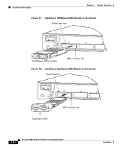
Front-Panel Description Chapter 1 Product Overview Figure 1-7 Installing a 1000BaseX GBIC Module in the Switch Metal flap door 18965 1 SYSTEM RPS MODE STATUS UTIL DUPLX SPEED 2 3 1000BaseX GBIC module GBIC module slot Figure 1-8 Installing a GigaStack GBIC Module in the Switch Metal flap door 22081 1 SYSTEM RPS MODE STATUS UTIL DUPLX SPEED 2 3 1 2 GigaStack GBIC GBIC module slot 1-10 Catalyst 3500 Series XL Hardware Installation Guide 78-6456-04
Front-Panel Description Chapter 1 Product Overview Figure 1-7 Installing a 1000BaseX GBIC Module in the Switch Metal flap door 18965 1 SYSTEM RPS MODE STATUS UTIL DUPLX SPEED 2 3 1000BaseX GBIC module GBIC module slot Figure 1-8 Installing a GigaStack GBIC Module in the Switch Metal flap door 22081 1 SYSTEM RPS MODE STATUS UTIL DUPLX SPEED 2 3 1 2 GigaStack GBIC GBIC module slot 1-10 Catalyst 3500 Series XL Hardware Installation Guide 78-6456-04
Installation Guide
Page 35
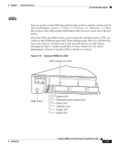
...location of the LEDs and the Mode button that you use the switch LEDs described in this section except the utilization meter (UTL) are visible on the VSM home page and Cluster Manager page. Figure 1-9 Catalyst 3508G XL LEDs GBIC module slot LEDs 18961 1 SYSTEM 2 3 RPS ...of the LEDs described in a cluster. The Cisco IOS Desktop Switching Software Configuration Guide describes how to use the Cluster Management Suite to monitor individual switches and how to use cluster management software to monitor all the switches in this section to monitor switch activity and its performance.
...location of the LEDs and the Mode button that you use the switch LEDs described in this section except the utilization meter (UTL) are visible on the VSM home page and Cluster Manager page. Figure 1-9 Catalyst 3508G XL LEDs GBIC module slot LEDs 18961 1 SYSTEM 2 3 RPS ...of the LEDs described in a cluster. The Cisco IOS Desktop Switching Software Configuration Guide describes how to use the Cluster Management Suite to monitor individual switches and how to use cluster management software to monitor all the switches in this section to monitor switch activity and its performance.

Installation Guide
Page 38
...and their meanings. System is not powered on page 2-17. 1-14 Catalyst 3500 Series XL Hardware Installation Guide 78-6456-04 For information on the System LED colors during POST, see the "Powering On the Switch and Running POST" section on . Table 1-3 System LED Color Off Green... Amber System Status System is operating normally. System is receiving power but is functioning properly. Front-Panel Description Figure 1-12 Catalyst 3548 XL LEDs Port LEDs Chapter 1 Product ...
...and their meanings. System is not powered on page 2-17. 1-14 Catalyst 3500 Series XL Hardware Installation Guide 78-6456-04 For information on the System LED colors during POST, see the "Powering On the Switch and Running POST" section on . Table 1-3 System LED Color Off Green... Amber System Status System is operating normally. System is receiving power but is functioning properly. Front-Panel Description Figure 1-12 Catalyst 3548 XL LEDs Port LEDs Chapter 1 Product ...

Installation Guide
Page 39
... be powered down and restarts after 15 seconds, using an RPS with a revision level lower than Z3 with a Catalyst 3508G XL or a Catalyst 3548 XL switch, the switch RPS LED might display amber (normally indicating an RPS malfunction) even when the RPS is connected but not functioning properly...or is not installed. RPS is functioning properly. The label on . Note The Cisco RPS 300 (model PWR300-AC-RPS) supports the Catalyst 3524-PWR XL switch. 78-6456-04 Catalyst 3500 Series XL Hardware Installation Guide 1-15 Chapter 1 Product Overview Front-Panel Description RPS LED The ...
... be powered down and restarts after 15 seconds, using an RPS with a revision level lower than Z3 with a Catalyst 3508G XL or a Catalyst 3548 XL switch, the switch RPS LED might display amber (normally indicating an RPS malfunction) even when the RPS is connected but not functioning properly...or is not installed. RPS is functioning properly. The label on . Note The Cisco RPS 300 (model PWR300-AC-RPS) supports the Catalyst 3524-PWR XL switch. 78-6456-04 Catalyst 3500 Series XL Hardware Installation Guide 1-15 Chapter 1 Product Overview Front-Panel Description RPS LED The ...

Installation Guide
Page 40
... LEDs Mode LED STAT UTL Port Mode Port status Switch utilization Description The port status. RPS is operating on the Cisco RPS 300, refer to interpret the port LED colors after you change the port mode in use by the switch. 1-16 Catalyst 3500 Series XL Hardware Installation Guide 78-6456-04 One of information...
... LEDs Mode LED STAT UTL Port Mode Port status Switch utilization Description The port status. RPS is operating on the Cisco RPS 300, refer to interpret the port LED colors after you change the port mode in use by the switch. 1-16 Catalyst 3500 Series XL Hardware Installation Guide 78-6456-04 One of information...


