
Hardware Installation Guide
Page 28
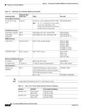
... for Cisco Access Routers Table 1-3 Cabling for Cisco Network Modules (continued) Connection Type Connector Type, Cable Color Service Module Connections To external storage array 68-pin D Token Ring Connections Token Ring, shielded Token Ring, unshielded WAN Connections T1/E1 WAN DB-9 RJ-45 RJ-48C/CA81A T3/DS3/E3 WAN BNC connector Wireless and.../E1 straight-through BNC T3/E3 coaxial NM-4T1-IMA NM-8T1-IMA NM-4E1-IMA NM-8E1-IMA NM-HDV2-1T1/E1 NM-HDV2-2T1/E1 NM-1T3/E3 NM-1A-T3 NM-1A-E3 NM-1A-T3/E3 BNC indoor IF coaxial 75-ohm F-connector shielded RG-6 NM-WMDA...
... for Cisco Access Routers Table 1-3 Cabling for Cisco Network Modules (continued) Connection Type Connector Type, Cable Color Service Module Connections To external storage array 68-pin D Token Ring Connections Token Ring, shielded Token Ring, unshielded WAN Connections T1/E1 WAN DB-9 RJ-45 RJ-48C/CA81A T3/DS3/E3 WAN BNC connector Wireless and.../E1 straight-through BNC T3/E3 coaxial NM-4T1-IMA NM-8T1-IMA NM-4E1-IMA NM-8E1-IMA NM-HDV2-1T1/E1 NM-HDV2-2T1/E1 NM-1T3/E3 NM-1A-T3 NM-1A-E3 NM-1A-T3/E3 BNC indoor IF coaxial 75-ohm F-connector shielded RG-6 NM-WMDA...
Hardware Installation Guide
Page 39
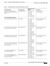
...-2T1/E1 Supported on Cisco Routers Cisco 2600 series Cisco 2811 Cisco 2821 Cisco 2851 Cisco 3700 series Cisco 3800 series See Section Connecting Voice Network Modules NM-16ESW NM-16ESW-1GIG NM-16ESW-PWR NM-16ESW-PWR-1GIG NM-36-ESW NMD-36-ESW-2GIG Cisco 2600 series Cisco 2811 Cisco 2821 Cisco 2851 Cisco 3600 series Cisco 3700 series Cisco 3800 series Cisco MWR 1941-DC Cisco 2600 series Cisco...
...-2T1/E1 Supported on Cisco Routers Cisco 2600 series Cisco 2811 Cisco 2821 Cisco 2851 Cisco 3700 series Cisco 3800 series See Section Connecting Voice Network Modules NM-16ESW NM-16ESW-1GIG NM-16ESW-PWR NM-16ESW-PWR-1GIG NM-36-ESW NMD-36-ESW-2GIG Cisco 2600 series Cisco 2811 Cisco 2821 Cisco 2851 Cisco 3600 series Cisco 3700 series Cisco 3800 series Cisco MWR 1941-DC Cisco 2600 series Cisco...
Hardware Installation Guide
Page 151
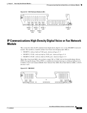
.../E1 ports, shown in Figure 8-13 • NM-HDV2-1T1/E1, with one built-in T1/E1 port, shown in Figure 8-14 • NM-HDV2-2T1/E1, with two built-in T1/E1 ports, shown in Figure 8-15 These three base-board SKUs also include a single VIC or VWIC slot for... section describes the IP communications high-density digital voice or fax (NM-HDV2) network module. PVDM 3 PVDM 2 V0 PVDM 1 PVDM 0 EN 95196 OL-2485-20 Cisco Network Modules Hardware Installation Guide 8-9
.../E1 ports, shown in Figure 8-13 • NM-HDV2-1T1/E1, with one built-in T1/E1 port, shown in Figure 8-14 • NM-HDV2-2T1/E1, with two built-in T1/E1 ports, shown in Figure 8-15 These three base-board SKUs also include a single VIC or VWIC slot for... section describes the IP communications high-density digital voice or fax (NM-HDV2) network module. PVDM 3 PVDM 2 V0 PVDM 1 PVDM 0 EN 95196 OL-2485-20 Cisco Network Modules Hardware Installation Guide 8-9

Hardware Installation Guide
Page 152
... T1, Frame Relay, Asynchronous Transfer Mode [ATM], and others). V0 AL LP CD CTRLR T1/E1 0 PVDM 1 PVDM 0 EN 95197 Figure 8-15 NM-HDV2-2T1/E1 NM-HDV2-2T1/E1 See Manual before Installation. AL PVDM 3 PVDM 2 LP CD CTRLR T1/E1 1 V0 AL LP CD CTRLR T1/E1 0 PVDM 1 PVDM 0 EN... before Installation. Table 8-2 Channels Per PVDM2 Module Type Module Name PVDM2-8 PVDM2-16 Max Channels for High Complexity1 4 6 Max Channels for Flexi Complexity3 4-8 6-16 8-10 Cisco Network Modules Hardware Installation Guide OL-2485-20
... T1, Frame Relay, Asynchronous Transfer Mode [ATM], and others). V0 AL LP CD CTRLR T1/E1 0 PVDM 1 PVDM 0 EN 95197 Figure 8-15 NM-HDV2-2T1/E1 NM-HDV2-2T1/E1 See Manual before Installation. AL PVDM 3 PVDM 2 LP CD CTRLR T1/E1 1 V0 AL LP CD CTRLR T1/E1 0 PVDM 1 PVDM 0 EN... before Installation. Table 8-2 Channels Per PVDM2 Module Type Module Name PVDM2-8 PVDM2-16 Max Channels for High Complexity1 4 6 Max Channels for Flexi Complexity3 4-8 6-16 8-10 Cisco Network Modules Hardware Installation Guide OL-2485-20
Hardware Installation Guide
Page 154
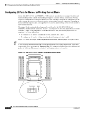
... Network Module Chapter 8 Connecting Voice Network Modules Configuring E1 Ports for Normal or Wetting Current Mode On the NM-HDV2-1T1/E1 and NM-HDV2-2T1/E1 network modules there is a small amount of electrical contacts in T1/E1 port that the jumper is not set to pins 2 and 3. These...E1 command to look for normal mode, with your E1 line is the jumper block for Normal Mode 135658 J6 J7 Pin 3 Pin 2 Pin 1 8-12 Cisco Network Modules Hardware Installation Guide OL-2485-20 Figure 8-16 shows the jumper block configured for line code violations and path code violations. The jumper...
... Network Module Chapter 8 Connecting Voice Network Modules Configuring E1 Ports for Normal or Wetting Current Mode On the NM-HDV2-1T1/E1 and NM-HDV2-2T1/E1 network modules there is a small amount of electrical contacts in T1/E1 port that the jumper is not set to pins 2 and 3. These...E1 command to look for normal mode, with your E1 line is the jumper block for Normal Mode 135658 J6 J7 Pin 3 Pin 2 Pin 1 8-12 Cisco Network Modules Hardware Installation Guide OL-2485-20 Figure 8-16 shows the jumper block configured for line code violations and path code violations. The jumper...
Hardware Installation Guide
Page 158
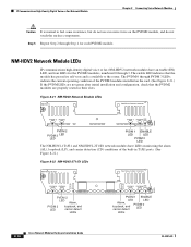
...and configuration, check that the module has passed its self-tests and is normal to the router. Figure 8-21 NM-HDV2 Network Module LEDs NM-HDV2 See Manual before Installation. 95203 ... EN PVDM 1 ENABLE LED LED Alarm, loopback, and carrier detect PVDM 0 LED LEDs 8-16 Cisco Network Modules Hardware Installation Guide OL-2485-20 Step 5 Repeat Step 2 through 3. The enable LED...modules are properly seated in T1/E1 ports. (See Figure 8-22.) Figure 8-22 NM-HDV2-2T1/E1 LEDs NM-HDV2-2T1/E1 See Manual before Installation. PVDM 3 PVDM 2 V0 PVDM 1 PVDM 0 EN 103881 PVDM...
...and configuration, check that the module has passed its self-tests and is normal to the router. Figure 8-21 NM-HDV2 Network Module LEDs NM-HDV2 See Manual before Installation. 95203 ... EN PVDM 1 ENABLE LED LED Alarm, loopback, and carrier detect PVDM 0 LED LEDs 8-16 Cisco Network Modules Hardware Installation Guide OL-2485-20 Step 5 Repeat Step 2 through 3. The enable LED...modules are properly seated in T1/E1 ports. (See Figure 8-22.) Figure 8-22 NM-HDV2-2T1/E1 LEDs NM-HDV2-2T1/E1 See Manual before Installation. PVDM 3 PVDM 2 V0 PVDM 1 PVDM 0 EN 103881 PVDM...