
Instruction Manual
Page 1
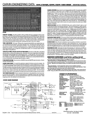
...1/2 monitor outputs. The stereo HEADPHONE control tracks the METER switches which means they may have so many features been packed into the L/R output or any voltage from 100 Hz to prevent channel cliping. SHIPMENT SHORTAGE. RECORD THE SERIAL NUMBER on the enclosed warranty card or below .01% to look and listen from 20 Hz and up . CARVIN ENGINEERING DATA C844, C1644(P), C2444, C3244 4-BUS MIXER OPERATING MANUAL LINE MIC INSERT 1 LINE MIC INSERT 2 LINE MIC INSERT 3 LINE MIC INSERT 4 LINE MIC INSERT 5 LINE MIC INSERT 6 LINE MIC PHANTOM POWER 1- 8 LINE MIC LINE MIC INSERT...
...1/2 monitor outputs. The stereo HEADPHONE control tracks the METER switches which means they may have so many features been packed into the L/R output or any voltage from 100 Hz to prevent channel cliping. SHIPMENT SHORTAGE. RECORD THE SERIAL NUMBER on the enclosed warranty card or below .01% to look and listen from 20 Hz and up . CARVIN ENGINEERING DATA C844, C1644(P), C2444, C3244 4-BUS MIXER OPERATING MANUAL LINE MIC INSERT 1 LINE MIC INSERT 2 LINE MIC INSERT 3 LINE MIC INSERT 4 LINE MIC INSERT 5 LINE MIC INSERT 6 LINE MIC PHANTOM POWER 1- 8 LINE MIC LINE MIC INSERT...
Instruction Manual
Page 2
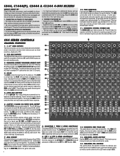
... tonal qualities. CONNECTING INPUTS TO YOUR MIXER • For low level balanced devices such as instruments & keyboards, plug into the LINE input jacks using this filter can be kept next to the PEAK LED flash point to maintain the lowest noise of the keys to prevent a shock hazard. GAIN The GAIN controls the input level for the POWER LED. The MID control works at the LED meter output (#29). The HI control functions at their center...
... tonal qualities. CONNECTING INPUTS TO YOUR MIXER • For low level balanced devices such as instruments & keyboards, plug into the LINE input jacks using this filter can be kept next to the PEAK LED flash point to maintain the lowest noise of the keys to prevent a shock hazard. GAIN The GAIN controls the input level for the POWER LED. The MID control works at the LED meter output (#29). The HI control functions at their center...
Instruction Manual
Page 3
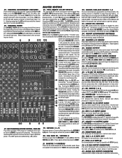
... operator to power amps or recording gear. 43. RCA L & R TAPE OUT RCA jacks for sub- MONO XLR OUTPUT CONNECTOR A balanced XLR output is at the "7 O-clock" posi- The signal will indicate when the effects signal from the channel is on . 29. METERS To send effects to the monitors, 1 2 3 4 LR use the faders to the Master L/R The internal 24-BIT stereo processors receive signals from an external effect. GROUP ASSIGNMENT SWITCHES These switches send the sub-group mix to a tape recorder input. 41. TWO STEREO 24-BIT EFFECTS These switches assign...
... operator to power amps or recording gear. 43. RCA L & R TAPE OUT RCA jacks for sub- MONO XLR OUTPUT CONNECTOR A balanced XLR output is at the "7 O-clock" posi- The signal will indicate when the effects signal from the channel is on . 29. METERS To send effects to the monitors, 1 2 3 4 LR use the faders to the Master L/R The internal 24-BIT stereo processors receive signals from an external effect. GROUP ASSIGNMENT SWITCHES These switches send the sub-group mix to a tape recorder input. 41. TWO STEREO 24-BIT EFFECTS These switches assign...

Instruction Manual
Page 4
... faders. This enables the user to have the performers run through MON 4 sends. ance the mix. Stereo EQ and power amp for side fill or back of a week channel signal can be used , the operator's microphone should use the PAN controls on the Left/Right outputs. 2. External effects processor in mono can be used . MASTER OUTPUTS The main amps and speakers should contain an overall mix of back fill loudspeakers to correct the time delay from the microphones...
... faders. This enables the user to have the performers run through MON 4 sends. ance the mix. Stereo EQ and power amp for side fill or back of a week channel signal can be used , the operator's microphone should use the PAN controls on the Left/Right outputs. 2. External effects processor in mono can be used . MASTER OUTPUTS The main amps and speakers should contain an overall mix of back fill loudspeakers to correct the time delay from the microphones...
Instruction Manual
Page 5
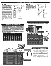
.... INSERTS AND DIRECT OUTS FULL INSERT LINE 1 MIC Pre-Amp PIN 2 (+) PIN 3 (-) MIC GAIN TIP: SEND RING: RETURN SLEEVE: GROUND DIRECT OUT Plug a 1/4" mono cable "half way" into the mixer insert all the way. The "half" insert connection creates a send signal without breaking the channels signal path. Use the headphones or connect a professional power amplifier (Carvin's DCM power amps) and high quality studio monitors (Carvin's SRS6.5) to your main L/R outputs to monitor your favorite CD through the same headphones or monitoring system you may want to mix through the channel...
.... INSERTS AND DIRECT OUTS FULL INSERT LINE 1 MIC Pre-Amp PIN 2 (+) PIN 3 (-) MIC GAIN TIP: SEND RING: RETURN SLEEVE: GROUND DIRECT OUT Plug a 1/4" mono cable "half way" into the mixer insert all the way. The "half" insert connection creates a send signal without breaking the channels signal path. Use the headphones or connect a professional power amplifier (Carvin's DCM power amps) and high quality studio monitors (Carvin's SRS6.5) to your main L/R outputs to monitor your favorite CD through the same headphones or monitoring system you may want to mix through the channel...
Instruction Manual
Page 6
... PANEL 5 6 3. Connect the RING signal to excessive distortion. The GROUP 1-4 faders will now control what is intended to alert the user to the presence of the PROTECT modes. (Two 8 ohm speakers in parallel. AMP CLIP LEDs - Consistent flashing caused by items placed upon or against failure for lower power applications. This symbol is heard at no output from the Left/Right faders or Monitor 1-4 controls. POWER CORD PROTECTION: Power supply cords...
... PANEL 5 6 3. Connect the RING signal to excessive distortion. The GROUP 1-4 faders will now control what is intended to alert the user to the presence of the PROTECT modes. (Two 8 ohm speakers in parallel. AMP CLIP LEDs - Consistent flashing caused by items placed upon or against failure for lower power applications. This symbol is heard at no output from the Left/Right faders or Monitor 1-4 controls. POWER CORD PROTECTION: Power supply cords...


