Service Manual
Page 3
... the principles of operation of the ADF in view of electrical and mechanical functions and in the field so as to their quality and performance. Chapter 11 Troubleshooting provides tables of periodically replaced parts and consumables/durables and scheduled servicing charts. It also ...may be installed using step-by -step basis. Appendix contains a general timing chart and general circuit diagrams. COPYRIGHT © 1999 CANON INC. It also explains the timing at which exposurerelated mechanisms are operated, and shows how they may be disassembled/assembled and adjusted....
... the principles of operation of the ADF in view of electrical and mechanical functions and in the field so as to their quality and performance. Chapter 11 Troubleshooting provides tables of periodically replaced parts and consumables/durables and scheduled servicing charts. It also ...may be installed using step-by -step basis. Appendix contains a general timing chart and general circuit diagrams. COPYRIGHT © 1999 CANON INC. It also explains the timing at which exposurerelated mechanisms are operated, and shows how they may be disassembled/assembled and adjusted....
Service Manual
Page 7
... the Main Motor (M1 2-5 E. Lens Drive Assembly ......... 3-31 C. CANON PC800s/900s REV.0 AUG. 1999 PRINTED IN JAPAN (IMPRIME AU JAPON) v ADF 1-8 III. Cross Section 1-13 IV. Outline of Operations 2-3 D. Copier 1-2 B. BASIC OPERATIONS 2-1 A. Varying the Reproduction Ratio 3-2 C. DISASSEMBLY/ASSEMBLY ..... 3-12 A. FEATURES 1-1 II. NAMES OF PARTS 1-10 A. USING THE MACHINE 1-15 A. Control Panel 1-15 V. IMAGE...
... the Main Motor (M1 2-5 E. Lens Drive Assembly ......... 3-31 C. CANON PC800s/900s REV.0 AUG. 1999 PRINTED IN JAPAN (IMPRIME AU JAPON) v ADF 1-8 III. Cross Section 1-13 IV. Outline of Operations 2-3 D. Copier 1-2 B. BASIC OPERATIONS 2-1 A. Varying the Reproduction Ratio 3-2 C. DISASSEMBLY/ASSEMBLY ..... 3-12 A. FEATURES 1-1 II. NAMES OF PARTS 1-10 A. USING THE MACHINE 1-15 A. Control Panel 1-15 V. IMAGE...
Service Manual
Page 9
...Original Jams ..... 8-16 J. External Covers 8-21 C. Storing the Cartridge with the Packaging Seal Removed 10-3 COPYRIGHT © 1999 CANON INC. Power Supply Circuit 7-4 C. Protecting the Power Supply Circuit 7-6 III. Outline 8-1 B Basic Construction 8-2 C. Power Supply ... H. MOVING THE MACHINE .......... 9-12 CHAPTER 10 MAINTENANCE AND SERVICING I . Copyboard Glass 7-16 D. PERIODICALLY REPLACED PARTS 10-1 II. Removing the ADF 8-19 B. External Covers 7-8 B. Storing and Handling the Cartridge with the Packaging Seal Intact ........ 10-2 B. FANS...
...Original Jams ..... 8-16 J. External Covers 8-21 C. Storing the Cartridge with the Packaging Seal Removed 10-3 COPYRIGHT © 1999 CANON INC. Power Supply Circuit 7-4 C. Protecting the Power Supply Circuit 7-6 III. Outline 8-1 B Basic Construction 8-2 C. Power Supply ... H. MOVING THE MACHINE .......... 9-12 CHAPTER 10 MAINTENANCE AND SERVICING I . Copyboard Glass 7-16 D. PERIODICALLY REPLACED PARTS 10-1 II. Removing the ADF 8-19 B. External Covers 7-8 B. Storing and Handling the Cartridge with the Packaging Seal Intact ........ 10-2 B. FANS...
Service Manual
Page 10
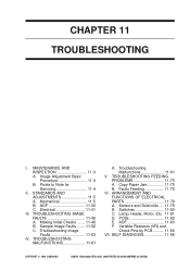
...H. HIGH VOLTAGE CONTACT CIRCUIT DIAGRAM A-32 L. BLANK EXPOSURE (rear) CIRCUIT DIAGRAM A-34 N. SOLVENTS/OILS A-36 viii COPYRIGHT © 1999 CANON INC. ADF 11-30 C. Electrical 11-41 III. Copy Paper Jam 11-75 B. Sensors and Solenoids .... 11-79 B. Lamp, Heater, Motor,... 11-3 B. Making Initial Checks ....... 11-48 B. Troubleshooting Malfunctions 11-61 V. ARRANGEMENT AND FUNCTIONS OF ELECTRICAL PARTS 11-79 A. PCBs 11-82 E. ADF 11-83 F. ADF CONTROLLER CIRCUIT DIAGRAM A-15 F. COMPOSITE POWER SUPPLY CIRCUIT DIAGRAM A-19 G. Faulty Feeding 11-78 VI. Switches ...
...H. HIGH VOLTAGE CONTACT CIRCUIT DIAGRAM A-32 L. BLANK EXPOSURE (rear) CIRCUIT DIAGRAM A-34 N. SOLVENTS/OILS A-36 viii COPYRIGHT © 1999 CANON INC. ADF 11-30 C. Electrical 11-41 III. Copy Paper Jam 11-75 B. Sensors and Solenoids .... 11-79 B. Lamp, Heater, Motor,... 11-3 B. Making Initial Checks ....... 11-48 B. Troubleshooting Malfunctions 11-61 V. ARRANGEMENT AND FUNCTIONS OF ELECTRICAL PARTS 11-79 A. PCBs 11-82 E. ADF 11-83 F. ADF CONTROLLER CIRCUIT DIAGRAM A-15 F. COMPOSITE POWER SUPPLY CIRCUIT DIAGRAM A-19 G. Faulty Feeding 11-78 VI. Switches ...
Service Manual
Page 11
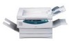
Cross Section 1-13 IV. USING THE MACHINE 1-15 A. Outline 1-20 COPYRIGHT © 1999 CANON INC. CHAPTER 1 GENERAL DESCRIPTION This chapter provides specifications of the machine, instructions on how to operate the machine, and an outline of copying process. NAMES OF PARTS 1-10 A. ROUTINE MAINTENANCE BY THE USER 1-17 VI. Control Panel 1-15 V. External View 1-10 B. IMAGE FORMATION 1-20 A. SPECIFICATIONS 1-2 A. CANON PC800s/900s REV.0 AUG. 1999 PRINTED IN JAPAN (IMPRIME AU JAPON) ADF 1-8 III. FEATURES 1-1 II. Copier 1-2 B. I.
Cross Section 1-13 IV. USING THE MACHINE 1-15 A. Outline 1-20 COPYRIGHT © 1999 CANON INC. CHAPTER 1 GENERAL DESCRIPTION This chapter provides specifications of the machine, instructions on how to operate the machine, and an outline of copying process. NAMES OF PARTS 1-10 A. ROUTINE MAINTENANCE BY THE USER 1-17 VI. Control Panel 1-15 V. External View 1-10 B. IMAGE FORMATION 1-20 A. SPECIFICATIONS 1-2 A. CANON PC800s/900s REV.0 AUG. 1999 PRINTED IN JAPAN (IMPRIME AU JAPON) ADF 1-8 III. FEATURES 1-1 II. Copier 1-2 B. I.
Service Manual
Page 224
... the following in mind: 1. ! As a rule, do not operate the machine with wider thread intervals). A few of its part removed. 7. DISASSEMBLY/ASSEMBLY As needed, disassemble/assemble the machine with a washer to ensure electrical continuity.) 5. Do not use any of...screws used are special screws (with any screws indiscriminately. 8-18 COPYRIGHT © 1999 CANON INC. CHAPTER 8 ADF II. CANON PC800S/900S REV.0 AUG. 1999 PRINTED IN JAPAN (IMPRIME AU JAPON) Unless otherwise instructed, assemble the parts by type (length, diameter) and location. 4. Before starting the work, turn ...
... the following in mind: 1. ! As a rule, do not operate the machine with wider thread intervals). A few of its part removed. 7. DISASSEMBLY/ASSEMBLY As needed, disassemble/assemble the machine with a washer to ensure electrical continuity.) 5. Do not use any of...screws used are special screws (with any screws indiscriminately. 8-18 COPYRIGHT © 1999 CANON INC. CHAPTER 8 ADF II. CANON PC800S/900S REV.0 AUG. 1999 PRINTED IN JAPAN (IMPRIME AU JAPON) Unless otherwise instructed, assemble the parts by type (length, diameter) and location. 4. Before starting the work, turn ...
Service Manual
Page 255
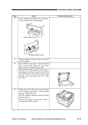
...only) 11 Gently lower the ADF and secure the main unit by taping in eight places, as packaging so that it in place. (Copyboard type only) Raise the ADF. COPYRIGHT © 1999 CANON INC. then, tape it will not open while in transit. Then, place two parts used as shown in place ...to the machine. CANON PC800s/900s REV.0 AUG. 1999 PRINTED IN JAPAN (IMPRIME AU JAPON) 9-13...
...only) 11 Gently lower the ADF and secure the main unit by taping in eight places, as packaging so that it in place. (Copyboard type only) Raise the ADF. COPYRIGHT © 1999 CANON INC. then, tape it will not open while in transit. Then, place two parts used as shown in place ...to the machine. CANON PC800s/900s REV.0 AUG. 1999 PRINTED IN JAPAN (IMPRIME AU JAPON) 9-13...
Service Manual
Page 264
ADF 11-30 C. Sample Image Faults ....... 11-52 C. Switches 11-80 C. CANON PC800s/900s REV.0 AUG. 1999 PRINTED IN JAPAN (IMPRIME AU JAPON) Making Initial Checks ....... 11-48 B. Troubleshooting Image Faults 11-53 IV...Servicing 11-4 II. Mechanical 11-5 B. Faulty Feeding 11-78 VI. PCBs 11-82 E. ARRANGEMENT AND FUNCTIONS OF ELECTRICAL PARTS 11-79 A. ADF 11-83 F. SELF DIAGNOSIS 11-86 COPYRIGHT © 1999 CANON INC. MAINTENANCE AND INSPECTION 11-3 A. TROUBLESHOOTING FEEDING PROBLEMS 11-75 A. Image Adjustment Basic Procedure 11-3 B. STANDARDS AND ...
ADF 11-30 C. Sample Image Faults ....... 11-52 C. Switches 11-80 C. CANON PC800s/900s REV.0 AUG. 1999 PRINTED IN JAPAN (IMPRIME AU JAPON) Making Initial Checks ....... 11-48 B. Troubleshooting Image Faults 11-53 IV...Servicing 11-4 II. Mechanical 11-5 B. Faulty Feeding 11-78 VI. PCBs 11-82 E. ARRANGEMENT AND FUNCTIONS OF ELECTRICAL PARTS 11-79 A. ADF 11-83 F. SELF DIAGNOSIS 11-86 COPYRIGHT © 1999 CANON INC. MAINTENANCE AND INSPECTION 11-3 A. TROUBLESHOOTING FEEDING PROBLEMS 11-75 A. Image Adjustment Basic Procedure 11-3 B. STANDARDS AND ...
Service Manual
Page 306
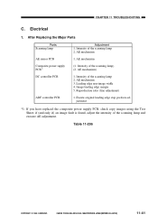
...AE mechanism) 1. if (and only if) an image fault is found, adjust the intensity of the scanning lamp) (2. CANON PC800s/900s REV.0 AUG. 1999 PRINTED IN JAPAN (IMPRIME AU JAPON) 11-41 Intensity of the scanning lamp and execute AE... adjustment. Reproduction ratio (fine adjustment) 1. Leading edge non-image width 4. After Replacing the Major Parts Parts Scanning lamp AE sensor PCB Composite power supply PCB*1 DC controller PCB ADF controller PCB Adjustment 1. Image leading edge margin 5. Electrical 1. Intensity of the scanning lamp 2. AE mechanism (1. ...
...AE mechanism) 1. if (and only if) an image fault is found, adjust the intensity of the scanning lamp) (2. CANON PC800s/900s REV.0 AUG. 1999 PRINTED IN JAPAN (IMPRIME AU JAPON) 11-41 Intensity of the scanning lamp and execute AE... adjustment. Reproduction ratio (fine adjustment) 1. Leading edge non-image width 4. After Replacing the Major Parts Parts Scanning lamp AE sensor PCB Composite power supply PCB*1 DC controller PCB ADF controller PCB Adjustment 1. Image leading edge margin 5. Electrical 1. Intensity of the scanning lamp 2. AE mechanism (1. ...


