CC5MPX and CC5MPXWD Digital Network Cameras
Page 5
...3.2 Installing Multimedia Player 3-1 3.3 ActiveX Controls in Internet Explorer 3-2 3.4 Setup Using Ethernet 3-2 3.5 Setup Using Device Configuration Utility 3-6 4. Camera Operation Using Web Browser Interface....7-1 7.1 Live Video Homepage 7-2 7.2 Network Configuration 7-3 7.2.1 Network Settings 7-5 7.2.2 Ethernet Power Mode Settings 7-5...Date and Time Update 7-12 7.3.3 Site Name 7-12 7.3.4 Users and Security 7-13 7.3.5 Digital I /O Cable Details 4-5 4.3 Ethernet Cables 4-5 5. CC5MPX Table of Contents PDF viewers: These page numbers refer to specific sections. 1. Use the ...
...3.2 Installing Multimedia Player 3-1 3.3 ActiveX Controls in Internet Explorer 3-2 3.4 Setup Using Ethernet 3-2 3.5 Setup Using Device Configuration Utility 3-6 4. Camera Operation Using Web Browser Interface....7-1 7.1 Live Video Homepage 7-2 7.2 Network Configuration 7-3 7.2.1 Network Settings 7-5 7.2.2 Ethernet Power Mode Settings 7-5...Date and Time Update 7-12 7.3.3 Site Name 7-12 7.3.4 Users and Security 7-13 7.3.5 Digital I /O Cable Details 4-5 4.3 Ethernet Cables 4-5 5. CC5MPX Table of Contents PDF viewers: These page numbers refer to specific sections. 1. Use the ...
CC5MPX and CC5MPXWD Digital Network Cameras
Page 8
FTP Server Settings 7-7 FIGURE 7-8. Automatic Date and Time Update 7-12 FIGURE 7-13. Digital I/O Settings 7-15 FIGURE 7-17. Event Logs 7-18 FIGURE 7-19. Example Display of Camera with Wires Attached 20-3 FIGURE 22-1. Image Capture Page 7-24 FIGURE 7-27. Self-Timed Capture Page 7-27 ... 19-2 FIGURE 19-3. Front Main Body O-ring 19-3 FIGURE 19-5. Backplate View 20-2 FIGURE 20-2. Inside of Files 7-20 FIGURE 7-23. CC5MPX USB Directory 22-2 iv SMTP Server Settings 7-9 FIGURE 7-9. Users and Security Settings 7-14 FIGURE 7-16. Serial PakBus Port Setting 9-1 FIGURE 9-2. RS...
FTP Server Settings 7-7 FIGURE 7-8. Automatic Date and Time Update 7-12 FIGURE 7-13. Digital I/O Settings 7-15 FIGURE 7-17. Event Logs 7-18 FIGURE 7-19. Example Display of Camera with Wires Attached 20-3 FIGURE 22-1. Image Capture Page 7-24 FIGURE 7-27. Self-Timed Capture Page 7-27 ... 19-2 FIGURE 19-3. Front Main Body O-ring 19-3 FIGURE 19-5. Backplate View 20-2 FIGURE 20-2. Inside of Files 7-20 FIGURE 7-23. CC5MPX USB Directory 22-2 iv SMTP Server Settings 7-9 FIGURE 7-9. Users and Security Settings 7-14 FIGURE 7-16. Serial PakBus Port Setting 9-1 FIGURE 9-2. RS...
CC5MPX and CC5MPXWD Digital Network Cameras
Page 11
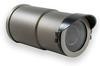
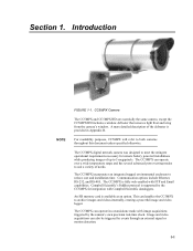
... CC5MPX digital network camera was designed to 5 megapixels. An SD memory card is provided in a stand-alone mode with FTP and Email capabilities. Image and video acquisitions can also be triggered by the CC5MPX for remote battery powered installations while producing images of up to meet the stringent operational requirements necessary for integration with Campbell Scientific...
... CC5MPX digital network camera was designed to 5 megapixels. An SD memory card is provided in a stand-alone mode with FTP and Email capabilities. Image and video acquisitions can also be triggered by the CC5MPX for remote battery powered installations while producing images of up to meet the stringent operational requirements necessary for integration with Campbell Scientific...

CC5MPX and CC5MPXWD Digital Network Cameras
Page 46
Section 7. The main System settings page has 7 Sub Tabs as follows: • Date and Time • Automatic Date and Time Update • Site Name • Users/Security • Digital I/O • Update • Events 7-10 FIGURE 7-10. Camera Operation Using Web Browser Interface FIGURE 7-9. SNTP Server Settings 7.3 System Configuration Selecting the System tab will activate the System Settings page (see FIGURE 7-10). System Settings
Section 7. The main System settings page has 7 Sub Tabs as follows: • Date and Time • Automatic Date and Time Update • Site Name • Users/Security • Digital I/O • Update • Events 7-10 FIGURE 7-10. Camera Operation Using Web Browser Interface FIGURE 7-9. SNTP Server Settings 7.3 System Configuration Selecting the System tab will activate the System Settings page (see FIGURE 7-10). System Settings
CC5MPX and CC5MPXWD Digital Network Cameras
Page 51
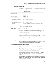
...Check the Campbell Scientific website for this purpose. 7-15 Some modems will require a warm up to a maximum of 750 mA of current. The Communication Warm up Time parameter allows an appropriate time to Active High. Camera Operation Using Web Browser Interface 7.3.5 Digital I/O Settings The Digital I/O sub... will be configured to a communication device such as the camera's input power (i.e., 12 Vdc). This option enables the CC5MPX to supply up time or a period to time to limit power consumption of the CC5MPX camera. FIGURE 7-16. The CC5MPX is a need to register on the Power I /O ...
...Check the Campbell Scientific website for this purpose. 7-15 Some modems will require a warm up to a maximum of 750 mA of current. The Communication Warm up Time parameter allows an appropriate time to Active High. Camera Operation Using Web Browser Interface 7.3.5 Digital I/O Settings The Digital I/O sub... will be configured to a communication device such as the camera's input power (i.e., 12 Vdc). This option enables the CC5MPX to supply up time or a period to time to limit power consumption of the CC5MPX camera. FIGURE 7-16. The CC5MPX is a need to register on the Power I /O ...

CC5MPX and CC5MPXWD Digital Network Cameras
Page 68
... is captured or video is started is typically less than 100 msec. The minimum required pulse period is applied to keep the camera in the active state will be greatly affected. Preferably pulses should also be configured for the External Trigger setup are as the ... are the same. 7.6.4 External Trigger The External Trigger sub tab (see Digital I/O Settings). The External Trigger can be short in TABLE 7-8. 7-32 The voltage levels are outlined in duration (only a few seconds). Camera Operation Using Web Browser Interface 7.6.3 Self Timed Capture2 Refer to the previous ...
... is captured or video is started is typically less than 100 msec. The minimum required pulse period is applied to keep the camera in the active state will be greatly affected. Preferably pulses should also be configured for the External Trigger setup are as the ... are the same. 7.6.4 External Trigger The External Trigger sub tab (see Digital I/O Settings). The External Trigger can be short in TABLE 7-8. 7-32 The voltage levels are outlined in duration (only a few seconds). Camera Operation Using Web Browser Interface 7.6.3 Self Timed Capture2 Refer to the previous ...

CC5MPX and CC5MPXWD Digital Network Cameras
Page 77
...banner. The text is as follows: ±TT.T C / SSSS +25.0 C / 1000 This text field allows a file name to accommodate the outside banners. Camera Operation Using Web Browser Interface TABLE 7-11. The time stamp will be noticeable distortions in the above or below the still image. The text entered... and the Serial number of the camera will be followed by the date and time: < Default File Name >_YYYY_MM_DD_HH_MM_SS.jpg • The Number Increment option will append a 10 digit counter to 32 characters. • The NONE option will use the same file name for the image sizes with ...
...banner. The text is as follows: ±TT.T C / SSSS +25.0 C / 1000 This text field allows a file name to accommodate the outside banners. Camera Operation Using Web Browser Interface TABLE 7-11. The time stamp will be noticeable distortions in the above or below the still image. The text entered... and the Serial number of the camera will be followed by the date and time: < Default File Name >_YYYY_MM_DD_HH_MM_SS.jpg • The Number Increment option will append a 10 digit counter to 32 characters. • The NONE option will use the same file name for the image sizes with ...