CC5MPX and CC5MPXWD Digital Network Cameras
Page 5
...5-1 5.2 Power I /O Cable Details 4-5 4.3 Ethernet Cables 4-5 5. Specifications 2-1 3. Use the PDF reader bookmarks tab for links to the printed version of this document. Camera Operation Using Web Browser Interface....7-1 7.1 Live Video Homepage 7-2 7.2 Network Configuration 7-3 7.2.1 Network Settings 7-5 7.2.2 Ethernet Power Mode Settings 7-5 7.2.3 FTP Server Setting 7-7 7.2.4 SMTP ... Date and Time Update 7-12 7.3.3 Site Name 7-12 7.3.4 Users and Security 7-13 7.3.5 Digital I/O Settings 7-15 i CC5MPX Table of Contents PDF viewers: These page numbers refer to specific sections...
...5-1 5.2 Power I /O Cable Details 4-5 4.3 Ethernet Cables 4-5 5. Specifications 2-1 3. Use the PDF reader bookmarks tab for links to the printed version of this document. Camera Operation Using Web Browser Interface....7-1 7.1 Live Video Homepage 7-2 7.2 Network Configuration 7-3 7.2.1 Network Settings 7-5 7.2.2 Ethernet Power Mode Settings 7-5 7.2.3 FTP Server Setting 7-7 7.2.4 SMTP ... Date and Time Update 7-12 7.3.3 Site Name 7-12 7.3.4 Users and Security 7-13 7.3.5 Digital I/O Settings 7-15 i CC5MPX Table of Contents PDF viewers: These page numbers refer to specific sections...

CC5MPX and CC5MPXWD Digital Network Cameras
Page 6
... PakBus Communications 11-1 12. Power Calculations and Timings 15-1 15.1 Standalone Operation 15-1 15.2 Operation with Communications 15-2 16. CC5MPX Table of View 14-2 14.2 Focus and Zoom Adjustment 14-3 14.2.1 Using the Focusing Number 14-3 14.3 Temperature Variations and Focus... Time Images 13-1 14. Remote Image Retrieval 17-1 17.1 LoggerNet File Retrieval 17-1 17.2 Using LoggerNet File Control 17-2 ii Lens 14-1 14.1 Camera Lens and Field of Contents 7.3.6 Update 7-16 7.3.7 Events 7-17 7.4 Memory Card 7-18 7.5 Video Settings 7-21 7.6 Image Capture 7-23 7.6.1 Power...
... PakBus Communications 11-1 12. Power Calculations and Timings 15-1 15.1 Standalone Operation 15-1 15.2 Operation with Communications 15-2 16. CC5MPX Table of View 14-2 14.2 Focus and Zoom Adjustment 14-3 14.2.1 Using the Focusing Number 14-3 14.3 Temperature Variations and Focus... Time Images 13-1 14. Remote Image Retrieval 17-1 17.1 LoggerNet File Retrieval 17-1 17.2 Using LoggerNet File Control 17-2 ii Lens 14-1 14.1 Camera Lens and Field of Contents 7.3.6 Update 7-16 7.3.7 Events 7-17 7.4 Memory Card 7-18 7.5 Video Settings 7-21 7.6 Image Capture 7-23 7.6.1 Power...

CC5MPX and CC5MPXWD Digital Network Cameras
Page 7
.... Quick Notes 23-1 23.1 CC5MPX General 23-1 23.2 Campbell Datalogger Users 23-2 23.3 Configuration Process 23-2 Appendices A. Network Connections 3-2 FIGURE 3-2. Local Area Connection 3-3 FIGURE 3-3. IP Address Configuration 3-4 FIGURE 3-5. CC5MPX Shown in Device Configuration Utility 3-7 FIGURE 3-7. For example, network connection only 4-4 FIGURE 4-4. Live Video (Homepage 7-2 FIGURE 7-3. CC5MPXWD Window Defroster Description......... Camera wired for stand-alone...
.... Quick Notes 23-1 23.1 CC5MPX General 23-1 23.2 Campbell Datalogger Users 23-2 23.3 Configuration Process 23-2 Appendices A. Network Connections 3-2 FIGURE 3-2. Local Area Connection 3-3 FIGURE 3-3. IP Address Configuration 3-4 FIGURE 3-5. CC5MPX Shown in Device Configuration Utility 3-7 FIGURE 3-7. For example, network connection only 4-4 FIGURE 4-4. Live Video (Homepage 7-2 FIGURE 7-3. CC5MPXWD Window Defroster Description......... Camera wired for stand-alone...
CC5MPX and CC5MPXWD Digital Network Cameras
Page 8
... Field of Contents FIGURE 7-6. CC5MPX Mounted to a 9-Pin RS-232 Port 9-2 FIGURE 9-3. SMTP Server Settings 7-9 FIGURE 7-9. Site Name 7-13 FIGURE 7-14. Digital I/O Settings 7-15 FIGURE 7-17. Example Display of Camera with Wires Attached 20-3 FIGURE 22-1. Video Settings Page 7-21 FIGURE 7-25.... Enable and Capture Time Values 7-28 FIGURE 7-30. RS-485 Shown in File Control 17-3 FIGURE 18-1. CC5MPX Lens Tube Removal 14-1 FIGURE 14-2. Button...
... Field of Contents FIGURE 7-6. CC5MPX Mounted to a 9-Pin RS-232 Port 9-2 FIGURE 9-3. SMTP Server Settings 7-9 FIGURE 7-9. Site Name 7-13 FIGURE 7-14. Digital I/O Settings 7-15 FIGURE 7-17. Example Display of Camera with Wires Attached 20-3 FIGURE 22-1. Video Settings Page 7-21 FIGURE 7-25.... Enable and Capture Time Values 7-28 FIGURE 7-30. RS-485 Shown in File Control 17-3 FIGURE 18-1. CC5MPX Lens Tube Removal 14-1 FIGURE 14-2. Button...
CC5MPX and CC5MPXWD Digital Network Cameras
Page 11
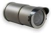
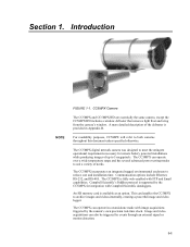
... modes to suit a variety of the defroster is fully web-enabled with image acquisitions triggered by the camera's own precision real-time clock. Campbell Scientific's PakBus protocol is available as an option. CC5MPX Camera The CC5MPX and CC5MPXWD are essentially the same camera, except the CC5MPXWD includes a window defroster that removes light frost and icing from the...
... modes to suit a variety of the defroster is fully web-enabled with image acquisitions triggered by the camera's own precision real-time clock. Campbell Scientific's PakBus protocol is available as an option. CC5MPX Camera The CC5MPX and CC5MPXWD are essentially the same camera, except the CC5MPXWD includes a window defroster that removes light frost and icing from the...

CC5MPX and CC5MPXWD Digital Network Cameras
Page 13
...mm, 27° to 80° field of 720P - 1280x720 (MPEG4), 640x480 (Live Video Only/MJPEG), 320x240 (MPEG4) Ext. contact Campbell Scientific for more information) Image or Video Capture Triggers: Two independent self timers Motion detection Web page control External trigger Still Image Resolution (JPEG): ...view (FOV) 10 to 40 mm, 9° to 16 Vdc Operating the CC5MPXWD camera and defroster at voltages higher than 16 Vdc may damage the camera. Specifications CAUTION CC5MPXWD Heating Element Resistance: Operating Power CC5MPX: CC5MPXWD: 18 Ohms 9 to 30 Vdc 9 to 35° FOV (ordered as...
...mm, 27° to 80° field of 720P - 1280x720 (MPEG4), 640x480 (Live Video Only/MJPEG), 320x240 (MPEG4) Ext. contact Campbell Scientific for more information) Image or Video Capture Triggers: Two independent self timers Motion detection Web page control External trigger Still Image Resolution (JPEG): ...view (FOV) 10 to 40 mm, 9° to 16 Vdc Operating the CC5MPXWD camera and defroster at voltages higher than 16 Vdc may damage the camera. Specifications CAUTION CC5MPXWD Heating Element Resistance: Operating Power CC5MPX: CC5MPXWD: 18 Ohms 9 to 30 Vdc 9 to 35° FOV (ordered as...
CC5MPX and CC5MPXWD Digital Network Cameras
Page 15
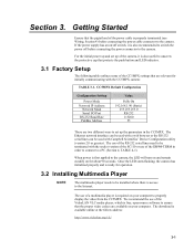
... is required on your computer to the Internet. If the power supply has an on/off before connecting the power connector to the camera, the LED will turn on and remain steadily on for initially communicating with the socket version of the SC110 or use of the...order to connect to ensure that the pigtail end of a multimedia player is access to properly display the video from the CC5MPX. The Ethernet network interface can be used with Campbell Scientifics' Device Configuration utility (version 2.0 or greater). We recommend the use of the power cable is free, open-source ...
... is required on your computer to the Internet. If the power supply has an on/off before connecting the power connector to the camera, the LED will turn on and remain steadily on for initially communicating with the socket version of the SC110 or use of the...order to connect to ensure that the pigtail end of a multimedia player is access to properly display the video from the CC5MPX. The Ethernet network interface can be used with Campbell Scientifics' Device Configuration utility (version 2.0 or greater). We recommend the use of the power cable is free, open-source ...
CC5MPX and CC5MPXWD Digital Network Cameras
Page 16
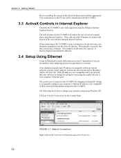
...in your network, then you should be 192.168.1.90. The following shows how to change the setting by connecting the camera directly to the CC5MPX via the Control Panel. FIGURE 3-1. When connecting to your network setting using the Windows Internet Explorer browser. If this ...you will be compatible with objects in Internet Explorer Currently the CC5MPX is in the form of ActiveX controls when using Internet Explorer. Network Connections Right click on a network. Getting Started Prior to installing the camera in Internet Explorer and should be allowed. 3.4 Setup Using ...
...in your network, then you should be 192.168.1.90. The following shows how to change the setting by connecting the camera directly to the CC5MPX via the Control Panel. FIGURE 3-1. When connecting to your network setting using the Windows Internet Explorer browser. If this ...you will be compatible with objects in Internet Explorer Currently the CC5MPX is in the form of ActiveX controls when using Internet Explorer. Network Connections Right click on a network. Getting Started Prior to installing the camera in Internet Explorer and should be allowed. 3.4 Setup Using ...
CC5MPX and CC5MPXWD Digital Network Cameras
Page 18
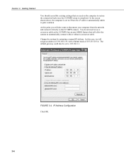
... to Obtain the IP address automatically which is completed. You do not need to use a crossover cable as the CC5MPX has an auto MDIX feature that are used on the computer to the CC5MPX camera. Change the settings by assigning a manual IP address. IP Address Configuration Click OK. 3-4 Getting Started You should record...
... to Obtain the IP address automatically which is completed. You do not need to use a crossover cable as the CC5MPX has an auto MDIX feature that are used on the computer to the CC5MPX camera. Change the settings by assigning a manual IP address. IP Address Configuration Click OK. 3-4 Getting Started You should record...

CC5MPX and CC5MPXWD Digital Network Cameras
Page 19
Right click on the Local Area connection again and select repair. Section 3. Once the computer establishes a connection with the camera, the following page should now be displayed in your Internet Browser. 3-5 In the above example, your web browser and access the camera by typing http://192.168.1.90. Getting Started Click OK again here. You should be able to open your computer was configured to at 192.168.1.90. Since you want to connect to the camera, the 192.168.1.90 is set to 192.168.1.91 and the camera is entered into the browser.
Right click on the Local Area connection again and select repair. Section 3. Once the computer establishes a connection with the camera, the following page should now be displayed in your Internet Browser. 3-5 In the above example, your web browser and access the camera by typing http://192.168.1.90. Getting Started Click OK again here. You should be able to open your computer was configured to at 192.168.1.90. Since you want to connect to the camera, the 192.168.1.90 is set to 192.168.1.91 and the camera is entered into the browser.
CC5MPX and CC5MPXWD Digital Network Cameras
Page 20
... the connection of the CC5MPXCBL1-L cable to enable the pop up for the camera. 3.5 Setup Using Device Configuration Utility Campbell Scientific provides a free software program called the Device Configuration Utility that supports the configuration of a variety of the utility. The CC5MPX comes with a DB9M-TERM that you have the most recent version of equipment...
... the connection of the CC5MPXCBL1-L cable to enable the pop up for the camera. 3.5 Setup Using Device Configuration Utility Campbell Scientific provides a free software program called the Device Configuration Utility that supports the configuration of a variety of the utility. The CC5MPX comes with a DB9M-TERM that you have the most recent version of equipment...

CC5MPX and CC5MPXWD Digital Network Cameras
Page 21
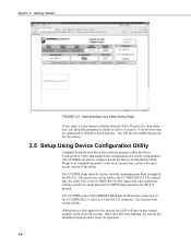
FIGURE 3-6. Once the settings are made, click the connect button. Once the appropriate selections are loaded, clicking the tabs located near the top of variable information so it may take about 30 seconds for this process to the various settings. 3-7 Select the CC5MPX as the device type and the appropriate COM port. CC5MPX Shown in Device Configuration Utility The camera has a large number of the page will allow navigation to complete. Getting Started The Device Configuration Utility can now be invoked. Section 3.
FIGURE 3-6. Once the settings are made, click the connect button. Once the appropriate selections are loaded, clicking the tabs located near the top of variable information so it may take about 30 seconds for this process to the various settings. 3-7 Select the CC5MPX as the device type and the appropriate COM port. CC5MPX Shown in Device Configuration Utility The camera has a large number of the page will allow navigation to complete. Getting Started The Device Configuration Utility can now be invoked. Section 3.

CC5MPX and CC5MPXWD Digital Network Cameras
Page 23
The camera switches the Input Power voltage to power a communication device. Section 4. NOTE It is essential that the Ground cable be changed in...Refer to Section 8 Internal Jumpers if the current RS-232 or RS-485 interface option needs to be connected first when wiring the camera to the datalogger or the power supply. TABLE 4-1. Refer to TABLE 4-2 to help determine which wires will need to be connected for... pair on a CR800, CR1000, or CR3000) RS-485B when configured to RS-485 This line is as shown in the camera. Cables/Wiring 4.1 Power and I/O Cable Connections The wiring for your...
The camera switches the Input Power voltage to power a communication device. Section 4. NOTE It is essential that the Ground cable be changed in...Refer to Section 8 Internal Jumpers if the current RS-232 or RS-485 interface option needs to be connected first when wiring the camera to the datalogger or the power supply. TABLE 4-1. Refer to TABLE 4-2 to help determine which wires will need to be connected for... pair on a CR800, CR1000, or CR3000) RS-485B when configured to RS-485 This line is as shown in the camera. Cables/Wiring 4.1 Power and I/O Cable Connections The wiring for your...

CC5MPX and CC5MPXWD Digital Network Cameras
Page 24
Connect to a gray terminal block or Connect to be triggering the camera to a communications modem. Connect to a gray terminal block White wire only needs to ground if left in the Fully On Power mode by leaving the ... not Used Always Always Green wire only needs to a gray terminal block For solar powered sites, the camera can also keep the camera in Factory Default settings Always 4-2 Connect to be connected if the camera will be connected when RS-232 or RS-485 communications are used with PakBus or the Device Configuration...
Connect to a gray terminal block or Connect to be triggering the camera to a communications modem. Connect to a gray terminal block White wire only needs to ground if left in the Fully On Power mode by leaving the ... not Used Always Always Green wire only needs to a gray terminal block For solar powered sites, the camera can also keep the camera in Factory Default settings Always 4-2 Connect to be connected if the camera will be connected when RS-232 or RS-485 communications are used with PakBus or the Device Configuration...

CC5MPX and CC5MPXWD Digital Network Cameras
Page 25
Section 4. Cables/Wiring CC5MPXCBL1 Wire Color Connection Black CR1000 Power G Red CR1000 12V Green CR1000 C2 White CR1000 C1 Yellow Gray Terminal Block Blue Gray Terminal Block Clear CR1000 G FIGURE 4-1. Connection Allows CR1000 to CR1000 CC5MPXCBL1 Wire Color Connection Black CR1000 Power G Red CR1000 12V Green CR1000 C2 White CR1000 C1 Yellow Gray Terminal Block Blue CR1000 C4 Clear CR1000 G FIGURE 4-2. Camera Connected to Trigger the Camera 4-3
Section 4. Cables/Wiring CC5MPXCBL1 Wire Color Connection Black CR1000 Power G Red CR1000 12V Green CR1000 C2 White CR1000 C1 Yellow Gray Terminal Block Blue Gray Terminal Block Clear CR1000 G FIGURE 4-1. Connection Allows CR1000 to CR1000 CC5MPXCBL1 Wire Color Connection Black CR1000 Power G Red CR1000 12V Green CR1000 C2 White CR1000 C1 Yellow Gray Terminal Block Blue CR1000 C4 Clear CR1000 G FIGURE 4-2. Camera Connected to Trigger the Camera 4-3

CC5MPX and CC5MPXWD Digital Network Cameras
Page 26
Cables/Wiring CC5MPXCBL1 Wire Color Connection Black PS100 G Red PS100 +12V Green Gray Terminal Block White PS100 G Yellow Gray Terminal Block Blue Gray Terminal Block Clear PS100 G FIGURE 4-3. Camera wired for stand-alone operation without datalogger. CC5MPXCBL1 Wire Color Connection Black CR1000 Power G Red CR1000 12V Green MD485 A White MD485 B Yellow Gray Terminal Block Blue Gray Terminal Block Clear MD485 G FIGURE 4-4. CC5MPX Connected to MD485 Multidrop Modem 4-4 For example, network connection only. Section 4.
Cables/Wiring CC5MPXCBL1 Wire Color Connection Black PS100 G Red PS100 +12V Green Gray Terminal Block White PS100 G Yellow Gray Terminal Block Blue Gray Terminal Block Clear PS100 G FIGURE 4-3. Camera wired for stand-alone operation without datalogger. CC5MPXCBL1 Wire Color Connection Black CR1000 Power G Red CR1000 12V Green MD485 A White MD485 B Yellow Gray Terminal Block Blue Gray Terminal Block Clear MD485 G FIGURE 4-4. CC5MPX Connected to MD485 Multidrop Modem 4-4 For example, network connection only. Section 4.

CC5MPX and CC5MPXWD Digital Network Cameras
Page 27
...Ethernet Cables The Ethernet connection is required in wet or harsh conditions, the CC5MPXCBL2-L Environmental Ethernet Cable needs to the camera in conjunction with a standard RJ45 connector. however, a heavier gauge of the CC5MPX is auto MDIX, therefore an Ethernet crossover cable is not required when connecting the... camera to provide an Ethernet connection between the CC5MPX and a network router, cellular modem, or laptop. A standard CAT5 (or better) Ethernet cable with RJ45 connectors can be used ...
...Ethernet Cables The Ethernet connection is required in wet or harsh conditions, the CC5MPXCBL2-L Environmental Ethernet Cable needs to the camera in conjunction with a standard RJ45 connector. however, a heavier gauge of the CC5MPX is auto MDIX, therefore an Ethernet crossover cable is not required when connecting the... camera to provide an Ethernet connection between the CC5MPX and a network router, cellular modem, or laptop. A standard CAT5 (or better) Ethernet cable with RJ45 connectors can be used ...

CC5MPX and CC5MPXWD Digital Network Cameras
Page 29
CC5MPX Connector Layout 5.1 Ethernet RJ-45 Connection The RJ45 connector on the camera is meant to interface the CC5MPX with an RJ45 connector can be securely attached to the Ethernet connector to a laptop. If a permanent Ethernet connection is removed, a ...standard cable with either a network router, cellular modem, or directly to provide an environmental seal. Camera Hardware Description ...
CC5MPX Connector Layout 5.1 Ethernet RJ-45 Connection The RJ45 connector on the camera is meant to interface the CC5MPX with an RJ45 connector can be securely attached to the Ethernet connector to a laptop. If a permanent Ethernet connection is removed, a ...standard cable with either a network router, cellular modem, or directly to provide an environmental seal. Camera Hardware Description ...

CC5MPX and CC5MPXWD Digital Network Cameras
Page 30
... the connector. 5.3 Setup Button/Status LED The Setup button is located behind a protective metal cap on for user feedback. NOTE The CC5MPX does not support the PakBus communication protocol over Ethernet. 5.2 Power I/O Connection The CC5MPXCBL1 cable must be taken to the camera. When making the cable connection to expose the Button/LED.
... the connector. 5.3 Setup Button/Status LED The Setup button is located behind a protective metal cap on for user feedback. NOTE The CC5MPX does not support the PakBus communication protocol over Ethernet. 5.2 Power I/O Connection The CC5MPXCBL1 cable must be taken to the camera. When making the cable connection to expose the Button/LED.

CC5MPX and CC5MPXWD Digital Network Cameras
Page 31
... completely shut down procedure. The secondary function of the Setup button is pushed, the CC5MPX enters a fully on by: • timeout (from any necessary configuration changes. The camera is being kept on power mode for a period of 10 minutes. Section 5. During this interval you are ...down for a period of the power saving modes that it . • The camera is exiting the off Rapid Flash 2 times per second Continuously On CC5MPX State No power or the camera is to wake the camera from the Setup Button press) • communications • asserted external trigger •...
... completely shut down procedure. The secondary function of the Setup button is pushed, the CC5MPX enters a fully on by: • timeout (from any necessary configuration changes. The camera is being kept on power mode for a period of 10 minutes. Section 5. During this interval you are ...down for a period of the power saving modes that it . • The camera is exiting the off Rapid Flash 2 times per second Continuously On CC5MPX State No power or the camera is to wake the camera from the Setup Button press) • communications • asserted external trigger •...