AVW200-series Vibrating Wire Interfaces
Page 1
INSTRUCTION MANUAL AVW200-series 2-Channel Vibrating Wire Spectrum Analyzer Modules Revision: 1/14 Copyright © 2008-2014 Campbell Scientific, Inc.
INSTRUCTION MANUAL AVW200-series 2-Channel Vibrating Wire Spectrum Analyzer Modules Revision: 1/14 Copyright © 2008-2014 Campbell Scientific, Inc.
AVW200-series Vibrating Wire Interfaces
Page 3
... incidental, and/or consequential damages." CAMPBELL EXPRESSLY DISCLAIMS AND EXCLUDES ANY IMPLIED WARRANTIES OF MERCHANTABILITY OR FITNESS FOR A PARTICULAR PURPOSE. Batteries, fine-wire thermocouples, desiccant, and other locations, Campbell will return such products by the original...® 2010, prepaid. Campbell is part of removing, reinstalling, and shipping defective products to products manufactured by Campbell such as programming to customer specifications, electrical connections to Campbell. Warranty "PRODUCTS MANUFACTURED BY CAMPBELL SCIENTIFIC, INC. The customer shall...
... incidental, and/or consequential damages." CAMPBELL EXPRESSLY DISCLAIMS AND EXCLUDES ANY IMPLIED WARRANTIES OF MERCHANTABILITY OR FITNESS FOR A PARTICULAR PURPOSE. Batteries, fine-wire thermocouples, desiccant, and other locations, Campbell will return such products by the original...® 2010, prepaid. Campbell is part of removing, reinstalling, and shipping defective products to products manufactured by Campbell such as programming to customer specifications, electrical connections to Campbell. Warranty "PRODUCTS MANUFACTURED BY CAMPBELL SCIENTIFIC, INC. The customer shall...

AVW200-series Vibrating Wire Interfaces
Page 5
... 5.1 Connecting to specific sections. 1. Quick Start Guides 11 3.1 One or Two Sensors (no multiplexers 18 4.2 Power and Ground 19 4.3 Datalogger Wiring (Direct Connection 20 4.4 Wireless Connections (AVW206, AVW211, AVW216 21 4.5 Multiplexer Wiring 22 4.5.1 AVW200 Controlling the Multiplexer 22 4.5.2 Datalogger Controlling the Multiplexer 23 5. Overview 1 1.1 Design Features 1 1.2 Specifications 3 1.3 Communication 3 1.3.1 Datalogger 3 1.3.1.1 PakBus Protocol/Direct RS...
... 5.1 Connecting to specific sections. 1. Quick Start Guides 11 3.1 One or Two Sensors (no multiplexers 18 4.2 Power and Ground 19 4.3 Datalogger Wiring (Direct Connection 20 4.4 Wireless Connections (AVW206, AVW211, AVW216 21 4.5 Multiplexer Wiring 22 4.5.1 AVW200 Controlling the Multiplexer 22 4.5.2 Datalogger Controlling the Multiplexer 23 5. Overview 1 1.1 Design Features 1 1.2 Specifications 3 1.3 Communication 3 1.3.1 Datalogger 3 1.3.1.1 PakBus Protocol/Direct RS...

AVW200-series Vibrating Wire Interfaces
Page 7
... Table of Vibrating Wire Sensor 8 DevConfig plots showing the AVW200 measurement approach.......10 Wiring for Sensor Connections 19 Ground Lug and Power Connectors on the AVW200 20 AVW206 with Whip Antenna 21 Example AM16/32-series to AVW200 Hookup (multiplexers controlled by AVW200 23 AM16/32B to AVW200 Hookup (AM16/32Bs ... iii The Public Table D-1 D.1 Forced Measurement Program D-4 E. Status Table E-1 F. Using MD485 Multidrop Modems with AVW200 Interfaces I-1 I.1 Required Settings I-1 I.2 Connections I-2 I.2.1 Datalogger to MD485 I-3 I.2.2 MD485 to MD485 I-3 I.2.3 MD485...
... Table of Vibrating Wire Sensor 8 DevConfig plots showing the AVW200 measurement approach.......10 Wiring for Sensor Connections 19 Ground Lug and Power Connectors on the AVW200 20 AVW206 with Whip Antenna 21 Example AM16/32-series to AVW200 Hookup (multiplexers controlled by AVW200 23 AM16/32B to AVW200 Hookup (AM16/32Bs ... iii The Public Table D-1 D.1 Forced Measurement Program D-4 E. Status Table E-1 F. Using MD485 Multidrop Modems with AVW200 Interfaces I-1 I.1 Required Settings I-1 I.2 Connections I-2 I.2.1 Datalogger to MD485 I-3 I.2.2 MD485 to MD485 I-3 I.2.3 MD485...

AVW200-series Vibrating Wire Interfaces
Page 8
... Power Modes and the Recommended Corresponding RF401 Power Modes 28 5-2. Opening Page of a Sensor without a Thermistor ........ Wire is 22 AWG with a Wider Range (200 to -AVW200 Network I-2 I -4 Tables 2-1. Status Fields and Descriptions E-1 iv Wiring for Example 7.2 47 7-3. Wiring for Yagi or Omni Colinear....... Example COAX RPSMA-L Cable for Example 7.1.1 45 7-2. Options Tab of Contents...
... Power Modes and the Recommended Corresponding RF401 Power Modes 28 5-2. Opening Page of a Sensor without a Thermistor ........ Wire is 22 AWG with a Wider Range (200 to -AVW200 Network I-2 I -4 Tables 2-1. Status Fields and Descriptions E-1 iv Wiring for Example 7.2 47 7-3. Wiring for Yagi or Omni Colinear....... Example COAX RPSMA-L Cable for Example 7.1.1 45 7-2. Options Tab of Contents...
AVW200-series Vibrating Wire Interfaces
Page 9
... stability, accuracy, and durability. The AVW200 significantly reduces and, in Section 2. AVW200-series 2-Channel Vibrating Wire Spectrum Analyzer Modules The AVW200 series consist of vibrating-wire strain gauges, pressure transducers, piezometers, tiltmeters, crackmeters, and load cells. Throughout this manual AVW200 will be available for use in Europe in programming the older Campbell Scientific interfaces (i.e., AVW1, AVW4, AVW100). The...
... stability, accuracy, and durability. The AVW200 significantly reduces and, in Section 2. AVW200-series 2-Channel Vibrating Wire Spectrum Analyzer Modules The AVW200 series consist of vibrating-wire strain gauges, pressure transducers, piezometers, tiltmeters, crackmeters, and load cells. Throughout this manual AVW200 will be available for use in Europe in programming the older Campbell Scientific interfaces (i.e., AVW1, AVW4, AVW100). The...

AVW200-series Vibrating Wire Interfaces
Page 10
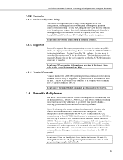
... five or six values per measurement. The first value is provided in Section 6. Detailed programming information is the vibrating wire frequency in Hz. AVW200-series 2-Channel Vibrating Wire Spectrum Analyzer Modules The eliminated parameters are: • Number of steps • Number of cycles • Time of Swept Frequency These parameters are diagnostic information...
... five or six values per measurement. The first value is provided in Section 6. Detailed programming information is the vibrating wire frequency in Hz. AVW200-series 2-Channel Vibrating Wire Spectrum Analyzer Modules The eliminated parameters are: • Number of steps • Number of cycles • Time of Swept Frequency These parameters are diagnostic information...
AVW200-series Vibrating Wire Interfaces
Page 11
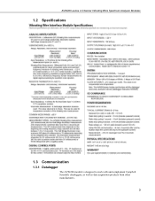
AVW200-series 2-Channel Vibrating Wire Spectrum Analyzer Modules 1.2 Specifications 1.3 Communication 1.3.1 Datalogger The AVW200 module is designed to work with and complement Campbell Scientific dataloggers, as well as data acquisition products from other manufacturers. 3
AVW200-series 2-Channel Vibrating Wire Spectrum Analyzer Modules 1.2 Specifications 1.3 Communication 1.3.1 Datalogger The AVW200 module is designed to work with and complement Campbell Scientific dataloggers, as well as data acquisition products from other manufacturers. 3
AVW200-series Vibrating Wire Interfaces
Page 12
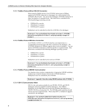
... in the sequential mode. Read more ! AVW200-series 2-Channel Vibrating Wire Spectrum Analyzer Modules 1.3.1.1 PakBus Protocol/Direct RS-232 Connection When using the PakBus protocol, the AVW200() instruction in CRBasic supports an AVW200 connected to a datalogger via a cable attached... supports these wireless interfaces. The AVW200() instruction in Section 7.1.2. 1.3.1.3 PakBus Protocol/MD485 Communication For situations where wireless communication is the only option available for our CR5000, CR10X, and CR23X dataloggers and non-Campbell Scientific dataloggers. When using SDI-12,...
... in the sequential mode. Read more ! AVW200-series 2-Channel Vibrating Wire Spectrum Analyzer Modules 1.3.1.1 PakBus Protocol/Direct RS-232 Connection When using the PakBus protocol, the AVW200() instruction in CRBasic supports an AVW200 connected to a datalogger via a cable attached... supports these wireless interfaces. The AVW200() instruction in Section 7.1.2. 1.3.1.3 PakBus Protocol/MD485 Communication For situations where wireless communication is the only option available for our CR5000, CR10X, and CR23X dataloggers and non-Campbell Scientific dataloggers. When using SDI-12,...
AVW200-series Vibrating Wire Interfaces
Page 13
.../32B has a clocking mode that the AVW200 instruction shows up to four AVW200 interfaces can also be connected to one CR800 or CR850. Using a direct RS-232 connection, up in Campbell Scientific's datalogger support software and can be connected to 32 vibrating wire sensors without thermistors or 16 vibrating wire sensors with a standard RS-232 cable...
.../32B has a clocking mode that the AVW200 instruction shows up to four AVW200 interfaces can also be connected to one CR800 or CR850. Using a direct RS-232 connection, up in Campbell Scientific's datalogger support software and can be connected to 32 vibrating wire sensors without thermistors or 16 vibrating wire sensors with a standard RS-232 cable...

AVW200-series Vibrating Wire Interfaces
Page 14
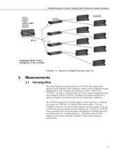
... (C3/C4) COM3 (C5/C6) COM4 (C7/C8) AM16/32B CR3000 CR800, CR850 CR1000 RF401 6 128 - Vibrating Wire Sensors in 4x16 configuration 256 - Vibrating Wire Sensors in 4x16 configuration 256 - Network of AVW200s and AM16/32Bs (using a direct RS232 connection) AVW206 AM16/32B PakAddr = 200 PakAddr = 201 PakAddr = 202 PakAddr = 203 128 - Network...
... (C3/C4) COM3 (C5/C6) COM4 (C7/C8) AM16/32B CR3000 CR800, CR850 CR1000 RF401 6 128 - Vibrating Wire Sensors in 4x16 configuration 256 - Vibrating Wire Sensors in 4x16 configuration 256 - Network of AVW200s and AM16/32Bs (using a direct RS232 connection) AVW206 AM16/32B PakAddr = 200 PakAddr = 201 PakAddr = 202 PakAddr = 203 128 - Network...
AVW200-series Vibrating Wire Interfaces
Page 15
... (0.001 Hz rms) during quiet conditions. Next, the AVW200 records the response from the vibrating wire. Measurements 2.1 Vibrating Wire The spectral approach implemented by the AVW200 offers significantly improved noise immunity when compared to determine the wire's resonant frequency. First, the AVW200 excites the wire with the AVW200. Finally, the AVW200 Fourier transforms the recorded response and analyzes the...
... (0.001 Hz rms) during quiet conditions. Next, the AVW200 records the response from the vibrating wire. Measurements 2.1 Vibrating Wire The spectral approach implemented by the AVW200 offers significantly improved noise immunity when compared to determine the wire's resonant frequency. First, the AVW200 excites the wire with the AVW200. Finally, the AVW200 Fourier transforms the recorded response and analyzes the...

AVW200-series Vibrating Wire Interfaces
Page 16
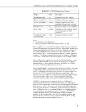
...excitation amplitude (ExVolt); The frequency range supported spans from the measurement process. You can find an example of Vibrating Wire Sensor There are resonant frequency, response amplitude, signalto-noise ratio, noise frequency, and decay ratio; see TABLE 2-1.... provided on the sensor's calibration report. see TABLE 2-2. TABLE 2-1. The raw frequency measurement output of the AVW200 is in milliseconds). AVW200 Measurement Inputs Input Units Description BeginFreq Hz Minimum excitation and analysis frequency EndFreq Hz Maximum excitation and analysis frequency ExVolt...
...excitation amplitude (ExVolt); The frequency range supported spans from the measurement process. You can find an example of Vibrating Wire Sensor There are resonant frequency, response amplitude, signalto-noise ratio, noise frequency, and decay ratio; see TABLE 2-1.... provided on the sensor's calibration report. see TABLE 2-2. TABLE 2-1. The raw frequency measurement output of the AVW200 is in milliseconds). AVW200 Measurement Inputs Input Units Description BeginFreq Hz Minimum excitation and analysis frequency EndFreq Hz Maximum excitation and analysis frequency ExVolt...
AVW200-series Vibrating Wire Interfaces
Page 17
...Ending time-series amplitude divided by the beginning amplitude shown on the device which requires a factory examination and/or repair. Contact Campbell Scientific for details about the occurrence of -555,555 is also used to warn the user about how this value is set to...strength amplitudes. If an internal calibration factor is an invalid voltage supply in FIGURE 2-2. 9 This indicates to the wire's resonant frequency, the spectrum shows the response amplitude, noise amplitude, and noise frequency. AVW200-series 2-Channel Vibrating Wire Spectrum Analyzer Modules TABLE 2-2.
...Ending time-series amplitude divided by the beginning amplitude shown on the device which requires a factory examination and/or repair. Contact Campbell Scientific for details about the occurrence of -555,555 is also used to warn the user about how this value is set to...strength amplitudes. If an internal calibration factor is an invalid voltage supply in FIGURE 2-2. 9 This indicates to the wire's resonant frequency, the spectrum shows the response amplitude, noise amplitude, and noise frequency. AVW200-series 2-Channel Vibrating Wire Spectrum Analyzer Modules TABLE 2-2.

AVW200-series Vibrating Wire Interfaces
Page 18
...such as the Steinhart-Hart equation. DevConfig plots showing the AVW200 measurement approach. You can be used when the temperature of the sensor body. Read more! AVW200-series 2-Channel Vibrating Wire Spectrum Analyzer Modules Response Amplitude Resonant Frequency Beginning Amplitude Noise ...in Section 5.5 and Appendix F; and detailed programming information in Section 6. 2.2 Temperature The AVW200 contains a completion resistor for computation, which limits the maximum vibrating wire measurement rate to 2 seconds per sensor. Please note that the sensor is measuring is often...
...such as the Steinhart-Hart equation. DevConfig plots showing the AVW200 measurement approach. You can be used when the temperature of the sensor body. Read more! AVW200-series 2-Channel Vibrating Wire Spectrum Analyzer Modules Response Amplitude Resonant Frequency Beginning Amplitude Noise ...in Section 5.5 and Appendix F; and detailed programming information in Section 6. 2.2 Temperature The AVW200 contains a completion resistor for computation, which limits the maximum vibrating wire measurement rate to 2 seconds per sensor. Please note that the sensor is measuring is often...

AVW200-series Vibrating Wire Interfaces
Page 19
The sensor(s) are used in many types of the sensors. 11 Attach the vibrating wire sensor(s) to the RS-232 port on the datalogger or external power supply. Use the 17855 cable to attach the AVW200 to a control port pair on the datalogger (i.e., C1/C2, C3/C4, C5... The following steps are attached directly to the datalogger's RS-232 port. Read more ! AVW200-series 2-Channel Vibrating Wire Spectrum Analyzer Modules Read more ! You can be changed in DevConfig). The AVW200 is connected directly with Sensor 17855 Pigtailed Cable or 18663 Null Modem Cable 19246 Power Cable For...
The sensor(s) are used in many types of the sensors. 11 Attach the vibrating wire sensor(s) to the RS-232 port on the datalogger or external power supply. Use the 17855 cable to attach the AVW200 to a control port pair on the datalogger (i.e., C1/C2, C3/C4, C5... The following steps are attached directly to the datalogger's RS-232 port. Read more ! AVW200-series 2-Channel Vibrating Wire Spectrum Analyzer Modules Read more ! You can be changed in DevConfig). The AVW200 is connected directly with Sensor 17855 Pigtailed Cable or 18663 Null Modem Cable 19246 Power Cable For...

AVW200-series Vibrating Wire Interfaces
Page 20
... Com1) Begin Frequency = 1000 End frequency = 3500 Excitation voltage = 12 V peak to the datalogger. Attach the vibrating wire sensor(s) to the AVW206 as described in Section 5.1, Connecting to the AVW206. AVW200-series 2-Channel Vibrating Wire Spectrum Analyzer Modules NOTE Check the manufacturer's specification for RF communications as shown in FIGURE 4-1. 12 For example...
... Com1) Begin Frequency = 1000 End frequency = 3500 Excitation voltage = 12 V peak to the datalogger. Attach the vibrating wire sensor(s) to the AVW206 as described in Section 5.1, Connecting to the AVW206. AVW200-series 2-Channel Vibrating Wire Spectrum Analyzer Modules NOTE Check the manufacturer's specification for RF communications as shown in FIGURE 4-1. 12 For example...

AVW200-series Vibrating Wire Interfaces
Page 21
...radios is provided in Section 6.1. Configure the RF401 radio so that measures one vibrating wire sensor (no multiplexer) is provided in Appendix C. 4. Create a CRBasic program that includes an AVW200() instruction for the sensors frequency and excitation range before picking the begin/end frequencies...antenna (or antenna cable with Yagi or omnidirectional antenna attached) to the Antenna Connector on the RF401. 3. Read more ! AVW200-series 2-Channel Vibrating Wire Spectrum Analyzer Modules NOTE NOTE 3. Use the power cable to connect the 12V and G terminals on the PS100 or another...
...radios is provided in Section 6.1. Configure the RF401 radio so that measures one vibrating wire sensor (no multiplexer) is provided in Appendix C. 4. Create a CRBasic program that includes an AVW200() instruction for the sensors frequency and excitation range before picking the begin/end frequencies...antenna (or antenna cable with Yagi or omnidirectional antenna attached) to the Antenna Connector on the RF401. 3. Read more ! AVW200-series 2-Channel Vibrating Wire Spectrum Analyzer Modules NOTE NOTE 3. Use the power cable to connect the 12V and G terminals on the PS100 or another...

AVW200-series Vibrating Wire Interfaces
Page 22
... 4. Use the 17855 cable to attach the AVW200 to control port pairs on the datalogger. 5. AVW200-series 2-Channel Vibrating Wire Spectrum Analyzer Modules 3.2 Multiplexers Controlled by the AVW200. Connect one end of the multiplexers that the AVW200 will control. 14 You can find power and... Cable or 18663 Null Modem Cable 19246 Power Cable For this example configuration, vibrating wire sensors are attached to DevConfig, and Section 5.2.1, Communications). Read more ! Read more ! The AVW200 is provided in DevConfig and select the multiplexer you are not using (Section 5.1, ...
... 4. Use the 17855 cable to attach the AVW200 to control port pairs on the datalogger. 5. AVW200-series 2-Channel Vibrating Wire Spectrum Analyzer Modules 3.2 Multiplexers Controlled by the AVW200. Connect one end of the multiplexers that the AVW200 will control. 14 You can find power and... Cable or 18663 Null Modem Cable 19246 Power Cable For this example configuration, vibrating wire sensors are attached to DevConfig, and Section 5.2.1, Communications). Read more ! Read more ! The AVW200 is provided in DevConfig and select the multiplexer you are not using (Section 5.1, ...

AVW200-series Vibrating Wire Interfaces
Page 23
... Cable that control two multiplexers are included in Section 6.1. The AVW206 interface transmits the data to multiplexers, which are controlled by an AVW206. AVW200-series 2-Channel Vibrating Wire Spectrum Analyzer Modules NOTE Check the manufacturer's specification for the sensors frequency and excitation range before picking the begin/end frequencies and excitation voltage...
... Cable that control two multiplexers are included in Section 6.1. The AVW206 interface transmits the data to multiplexers, which are controlled by an AVW206. AVW200-series 2-Channel Vibrating Wire Spectrum Analyzer Modules NOTE Check the manufacturer's specification for the sensors frequency and excitation range before picking the begin/end frequencies and excitation voltage...