
AVW200-series Vibrating Wire Interfaces
Page 7
...5-3. 5-4. 5-5. 5-6. Table of Vibrating Wire Sensor 8 DevConfig plots showing the AVW200 measurement approach.......10 Wiring for Sensor Connections 19 Ground Lug and Power Connectors on the AVW200 20 AVW206 with Whip Antenna 21 Example AM16/32-series to AVW200 Hookup (multiplexers controlled by AVW200 23 AM16/32B to AVW200 Hookup (AM16/32Bs controlled by datalogger...232 connection 6 Network of AVW206s and AM16/32Bs (wireless 6 Network of AVW200 Interfaces (SDI-12 7 Cutaway of Contents D. Time Series and Spectrum Graph Information .... CR10X Programming Example G-1 ...
...5-3. 5-4. 5-5. 5-6. Table of Vibrating Wire Sensor 8 DevConfig plots showing the AVW200 measurement approach.......10 Wiring for Sensor Connections 19 Ground Lug and Power Connectors on the AVW200 20 AVW206 with Whip Antenna 21 Example AM16/32-series to AVW200 Hookup (multiplexers controlled by AVW200 23 AM16/32B to AVW200 Hookup (AM16/32Bs controlled by datalogger...232 connection 6 Network of AVW206s and AM16/32Bs (wireless 6 Network of AVW200 Interfaces (SDI-12 7 Cutaway of Contents D. Time Series and Spectrum Graph Information .... CR10X Programming Example G-1 ...
AVW200-series Vibrating Wire Interfaces
Page 9
... departure from one major problem- To simplify programming of the wireless versions are discussed in detail in programming the older Campbell Scientific interfaces (i.e., AVW1, AVW4, AVW100). Read more! AVW200-series 2-Channel Vibrating Wire Spectrum Analyzer Modules The AVW200 series consist of vibrating-wire strain gauges, pressure transducers, piezometers, tiltmeters, crackmeters, and load cells. The different model numbers of the...
... departure from one major problem- To simplify programming of the wireless versions are discussed in detail in programming the older Campbell Scientific interfaces (i.e., AVW1, AVW4, AVW100). Read more! AVW200-series 2-Channel Vibrating Wire Spectrum Analyzer Modules The AVW200 series consist of vibrating-wire strain gauges, pressure transducers, piezometers, tiltmeters, crackmeters, and load cells. The different model numbers of the...
AVW200-series Vibrating Wire Interfaces
Page 12
... cable attached to a corresponding spread spectrum radio that is impractical, MD485 multidrop modems may extend the distance between the AVW200 interfaces. This instruction is contained in the following datalogger operating systems: • CR800std.06 or greater • CR1000std.15...CR5000, CR10X, and CR23X dataloggers and non-Campbell Scientific dataloggers. You can run in the sequential mode. AVW200-series 2-Channel Vibrating Wire Spectrum Analyzer Modules 1.3.1.1 PakBus Protocol/Direct RS-232 Connection When using MD485 modems with AVW200s. 1.3.1.4 SDI-12 Communication Mode SDI-12 ...
... cable attached to a corresponding spread spectrum radio that is impractical, MD485 multidrop modems may extend the distance between the AVW200 interfaces. This instruction is contained in the following datalogger operating systems: • CR800std.06 or greater • CR1000std.15...CR5000, CR10X, and CR23X dataloggers and non-Campbell Scientific dataloggers. You can run in the sequential mode. AVW200-series 2-Channel Vibrating Wire Spectrum Analyzer Modules 1.3.1.1 PakBus Protocol/Direct RS-232 Connection When using MD485 modems with AVW200s. 1.3.1.4 SDI-12 Communication Mode SDI-12 ...
AVW200-series Vibrating Wire Interfaces
Page 13
... to be connected to download the most recent OS for the datalogger. Up to 32 vibrating wire sensors without thermistors or 16 vibrating wire sensors with Multiplexers For the AVW200 interfaces, the AM16/32B multiplexer is provided in Campbell Scientific's datalogger support software and can be connected to a computer with one datalogger when using LoggerNet 3.4.1 or lower, the...
... to be connected to download the most recent OS for the datalogger. Up to 32 vibrating wire sensors without thermistors or 16 vibrating wire sensors with Multiplexers For the AVW200 interfaces, the AM16/32B multiplexer is provided in Campbell Scientific's datalogger support software and can be connected to a computer with one datalogger when using LoggerNet 3.4.1 or lower, the...
AVW200-series Vibrating Wire Interfaces
Page 15
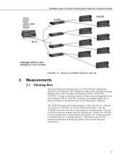
... implemented by other vibrating-wire interfaces (AVW1, AVW4, and AVW100). Measurements 2.1 Vibrating Wire The spectral approach implemented by the AVW200 offers significantly improved noise immunity when compared to determine the wire's resonant frequency. CR10X CR5000 CR23X CR800, CR850 CR1000 CR3000 SDI-12 AVW200-series 2-Channel Vibrating Wire Spectrum Analyzer Modules AVW200 0 AM16/32B 1 2 3 Datalogger MUST Control Multiplexers in a vibrating wire sensor (see FIGURE...
... implemented by other vibrating-wire interfaces (AVW1, AVW4, and AVW100). Measurements 2.1 Vibrating Wire The spectral approach implemented by the AVW200 offers significantly improved noise immunity when compared to determine the wire's resonant frequency. CR10X CR5000 CR23X CR800, CR850 CR1000 CR3000 SDI-12 AVW200-series 2-Channel Vibrating Wire Spectrum Analyzer Modules AVW200 0 AM16/32B 1 2 3 Datalogger MUST Control Multiplexers in a vibrating wire sensor (see FIGURE...

AVW200-series Vibrating Wire Interfaces
Page 16
... the excitation amplitude (ExVolt); TABLE 2-1. AVW200-series 2-Channel Vibrating Wire Spectrum Analyzer Modules Diaphragm Vibrating Wire Plucking/ Pickup Coil FIGURE 2-1. The raw frequency measurement output of Vibrating Wire Sensor There are three user-determined inputs to the AVW200 measurement process and five outputs from 100 Hz...to 6500 Hz. The frequency range supported spans from the measurement process. Cutaway of the AVW200 is in Hertz unlike our previous interfaces, which output kHz2 or 1/T2 (where T is converted to displacement in milliseconds). see TABLE 2-2.
... the excitation amplitude (ExVolt); TABLE 2-1. AVW200-series 2-Channel Vibrating Wire Spectrum Analyzer Modules Diaphragm Vibrating Wire Plucking/ Pickup Coil FIGURE 2-1. The raw frequency measurement output of Vibrating Wire Sensor There are three user-determined inputs to the AVW200 measurement process and five outputs from 100 Hz...to 6500 Hz. The frequency range supported spans from the measurement process. Cutaway of the AVW200 is in Hertz unlike our previous interfaces, which output kHz2 or 1/T2 (where T is converted to displacement in milliseconds). see TABLE 2-2.

AVW200-series Vibrating Wire Interfaces
Page 20
...2) Read more! The AVW206 interface transmits the data to an RF401 spread spectrum radio that is included in Section 7.1.1. 3.1.2 Wireless Connection Onsite Sensors AVW206 Sensors RF401 Office Datalogger Power Supply Cable that measures two vibrating wire sensors (no multiplexer) is ...the sensor(s) are attached directly to the AVW206. A thorough description of the AVW200() instruction and its parameters is provided in FIGURE 4-1. 12 AVW200-series 2-Channel Vibrating Wire Spectrum Analyzer Modules NOTE Check the manufacturer's specification for RF communications as shown in...
...2) Read more! The AVW206 interface transmits the data to an RF401 spread spectrum radio that is included in Section 7.1.1. 3.1.2 Wireless Connection Onsite Sensors AVW206 Sensors RF401 Office Datalogger Power Supply Cable that measures two vibrating wire sensors (no multiplexer) is ...the sensor(s) are attached directly to the AVW206. A thorough description of the AVW200() instruction and its parameters is provided in FIGURE 4-1. 12 AVW200-series 2-Channel Vibrating Wire Spectrum Analyzer Modules NOTE Check the manufacturer's specification for RF communications as shown in...

AVW200-series Vibrating Wire Interfaces
Page 23
... RF401 Office Datalogger Power Supply Cable that is provided in Section 6.1. AVW200-series 2-Channel Vibrating Wire Spectrum Analyzer Modules NOTE Check the manufacturer's specification for the sensors frequency and excitation range before picking the begin/end frequencies and excitation voltage. The AVW206 interface transmits the data to an RF401 spread spectrum radio that Comes...
... RF401 Office Datalogger Power Supply Cable that is provided in Section 6.1. AVW200-series 2-Channel Vibrating Wire Spectrum Analyzer Modules NOTE Check the manufacturer's specification for the sensors frequency and excitation range before picking the begin/end frequencies and excitation voltage. The AVW206 interface transmits the data to an RF401 spread spectrum radio that Comes...
AVW200-series Vibrating Wire Interfaces
Page 30
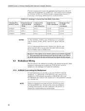
... terminals, and another CABLE4CBL cable or the MUXPOWER cable connects to have the AVW200 control the multiplexer. NOTE When two multiplexers are not compatible with the RF450, RF400, RF410, and RF415 spread spectrum radios. (2) For communication between the vibrating wire interface and spread spectrum radio to be successful, the radio's Protocol must be connected...
... terminals, and another CABLE4CBL cable or the MUXPOWER cable connects to have the AVW200 control the multiplexer. NOTE When two multiplexers are not compatible with the RF450, RF400, RF410, and RF415 spread spectrum radios. (2) For communication between the vibrating wire interface and spread spectrum radio to be successful, the radio's Protocol must be connected...

AVW200-series Vibrating Wire Interfaces
Page 35
... CRBasic program that the "Protocol" setting for the RF401-series radio must match the RF401 settings for communications between the interface and radio to be successful. Please note that will control the AVW200. Valid entries are 1 - 4094. Each device in which you want to communicate. PakBus Address-enter a PakBus Address that ... are 0-6. 27 Deployment Communications Editor in DevConfig NOTE Certain AVW206 settings must be set to either "PakBus Aware" or "PakBus Node" for the "Protocol" setting. AVW200-series 2-Channel Vibrating Wire Spectrum Analyzer Modules FIGURE 5-2.
... CRBasic program that the "Protocol" setting for the RF401-series radio must match the RF401 settings for communications between the interface and radio to be successful. Please note that will control the AVW200. Valid entries are 1 - 4094. Each device in which you want to communicate. PakBus Address-enter a PakBus Address that ... are 0-6. 27 Deployment Communications Editor in DevConfig NOTE Certain AVW206 settings must be set to either "PakBus Aware" or "PakBus Node" for the "Protocol" setting. AVW200-series 2-Channel Vibrating Wire Spectrum Analyzer Modules FIGURE 5-2.

AVW200-series Vibrating Wire Interfaces
Page 49
... would correctly be 41 However, in communication, the destination variables for each AVW200( ) instruction, this situation can use the same "Result" variable. The AVW200 interface module then determines how much time previous to the datalogger's interval it should start making the vibrating wire measurement, so that the data values have different "Result" variables for each...
... would correctly be 41 However, in communication, the destination variables for each AVW200( ) instruction, this situation can use the same "Result" variable. The AVW200 interface module then determines how much time previous to the datalogger's interval it should start making the vibrating wire measurement, so that the data values have different "Result" variables for each...

AVW200-series Vibrating Wire Interfaces
Page 52
... more! The Vendor ID "Campbell" (8 Characters) 4. Hence, when communicating with Multiplexers The AVW200 interface module cannot control multiplexers in the datalogger program and by connecting the clock and reset lines of an extended command is achieved by using PortSet instructions in the SDI-12 communication mode. AVW200-series 2-Channel Vibrating Wire Spectrum Analyzer Modules If a check...
... more! The Vendor ID "Campbell" (8 Characters) 4. Hence, when communicating with Multiplexers The AVW200 interface module cannot control multiplexers in the datalogger program and by connecting the clock and reset lines of an extended command is achieved by using PortSet instructions in the SDI-12 communication mode. AVW200-series 2-Channel Vibrating Wire Spectrum Analyzer Modules If a check...

AVW200-series Vibrating Wire Interfaces
Page 56
AVW200-series 2-Channel Vibrating Wire Spectrum Analyzer Modules 7.3 AVW200( ) Instruction Running in the Pipeline Mode The following program is an example of how to run the AVW200 with a CR1000 using multiple AVW200( ) instructions in the pipeline mode of the multiplexers will retry communications three times before the CR1000's execution interval. The AVW200 interface... "Result" variables for each AVW200 channel. Note that it should start making the vibrating wire measurement, so that the "Result" variable in the pipeline mode. TABLE 7-3 shows wiring used for Cable Attachment COM1 ...
AVW200-series 2-Channel Vibrating Wire Spectrum Analyzer Modules 7.3 AVW200( ) Instruction Running in the Pipeline Mode The following program is an example of how to run the AVW200 with a CR1000 using multiple AVW200( ) instructions in the pipeline mode of the multiplexers will retry communications three times before the CR1000's execution interval. The AVW200 interface... "Result" variables for each AVW200 channel. Note that it should start making the vibrating wire measurement, so that the "Result" variable in the pipeline mode. TABLE 7-3 shows wiring used for Cable Attachment COM1 ...

AVW200-series Vibrating Wire Interfaces
Page 57
... (time out is then executed and repeats the process. AVW200-series 2-Channel Vibrating Wire Spectrum Analyzer Modules ' Example Program running in the sequential mode, programs that contain multiple AVW200 instructions using the same COM port should have different result code...,Efreq,Xvolt,_60Hz,1,0) NextScan EndProg 7.4 AVW200( ) Instruction Running in the Sequential Mode Examples 7.4.1 and 7.4.2 run the AVW200 with the attached AVW200 interface module using multiple AVW200( ) instructions in order to make sixteen measurements. The next AVW200 instruction on channel 2 is two times...
... (time out is then executed and repeats the process. AVW200-series 2-Channel Vibrating Wire Spectrum Analyzer Modules ' Example Program running in the sequential mode, programs that contain multiple AVW200 instructions using the same COM port should have different result code...,Efreq,Xvolt,_60Hz,1,0) NextScan EndProg 7.4 AVW200( ) Instruction Running in the Sequential Mode Examples 7.4.1 and 7.4.2 run the AVW200 with the attached AVW200 interface module using multiple AVW200( ) instructions in order to make sixteen measurements. The next AVW200 instruction on channel 2 is two times...

AVW200-series Vibrating Wire Interfaces
Page 59
... program is achieved by using DevConfig. Extended SDI-12 commands can be controlled by the datalogger. The AVW200 interface module cannot control multiplexers in the AVW200 settings using PortSet instructions in the datalogger program (see example below) and by connecting the clock and ...on the datalogger. This is an example of how to run the AVW200 with the AVW200, the clock and reset lines of the AVW200 are not used to control ports on the SDI-12 measurement command issued. AVW200-series 2-Channel Vibrating Wire Spectrum Analyzer Modules Const Chan1 = 1 Const Chan2 = 2 Const ...
... program is achieved by using DevConfig. Extended SDI-12 commands can be controlled by the datalogger. The AVW200 interface module cannot control multiplexers in the AVW200 settings using PortSet instructions in the datalogger program (see example below) and by connecting the clock and ...on the datalogger. This is an example of how to run the AVW200 with the AVW200, the clock and reset lines of the AVW200 are not used to control ports on the SDI-12 measurement command issued. AVW200-series 2-Channel Vibrating Wire Spectrum Analyzer Modules Const Chan1 = 1 Const Chan2 = 2 Const ...

AVW200-series Vibrating Wire Interfaces
Page 62
... voltage The power supply battery may have discharged too low too many times, ruining the battery. AVW200-series 2-Channel Vibrating Wire Spectrum Analyzer Modules 8. The red LED at the front of the AVW200 will remain lit for 15 seconds on initial power up and then blink intermittently. (2) The... properly due to solar panel orientation, poor connection, or due to be SDC7 (or whatever active interface the RF401 is powered. Verify that : (1) The AVW200 is set wrong The active interface on initial power up and then blink intermittently. 2. The red LED at the front of the datalogger...
... voltage The power supply battery may have discharged too low too many times, ruining the battery. AVW200-series 2-Channel Vibrating Wire Spectrum Analyzer Modules 8. The red LED at the front of the AVW200 will remain lit for 15 seconds on initial power up and then blink intermittently. (2) The... properly due to solar panel orientation, poor connection, or due to be SDC7 (or whatever active interface the RF401 is powered. Verify that : (1) The AVW200 is set wrong The active interface on initial power up and then blink intermittently. 2. The red LED at the front of the datalogger...