AVW200-series Vibrating Wire Interfaces
Page 1
INSTRUCTION MANUAL AVW200-series 2-Channel Vibrating Wire Spectrum Analyzer Modules Revision: 1/14 Copyright © 2008-2014 Campbell Scientific, Inc.
INSTRUCTION MANUAL AVW200-series 2-Channel Vibrating Wire Spectrum Analyzer Modules Revision: 1/14 Copyright © 2008-2014 Campbell Scientific, Inc.

AVW200-series Vibrating Wire Interfaces
Page 7
... approach.......10 Wiring for Sensor Connections 19 Ground Lug and Power Connectors on the AVW200 20 AVW206 with Whip Antenna 21 Example AM16/32-series to AVW200 Hookup (multiplexers controlled by AVW200 23 AM16/32B to AVW200 Hookup (AM16/32Bs controlled by datalogger 24 Opening Page in DevConfig 26 Deployment Communications Editor in DevConfig 27...
... approach.......10 Wiring for Sensor Connections 19 Ground Lug and Power Connectors on the AVW200 20 AVW206 with Whip Antenna 21 Example AM16/32-series to AVW200 Hookup (multiplexers controlled by AVW200 23 AM16/32B to AVW200 Hookup (AM16/32Bs controlled by datalogger 24 Opening Page in DevConfig 26 Deployment Communications Editor in DevConfig 27...
AVW200-series Vibrating Wire Interfaces
Page 9
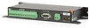
...1. Patent No. 7,779,690 1 AVW200-series 2-Channel Vibrating Wire Spectrum Analyzer Modules The AVW200 series consist of vibrating-wire strain gauges, pressure transducers, piezometers, tiltmeters, crackmeters, and load cells. The AVW200 significantly reduces and, in Europe after... AVW200 module allows the measurement of a base model (AVW200) and three wireless models (AVW206, AVW211, AVW216). external noise. Throughout this manual AVW200 will be measured by advancement in technology and mathematical processingi, resulting in programming the older Campbell Scientific ...
...1. Patent No. 7,779,690 1 AVW200-series 2-Channel Vibrating Wire Spectrum Analyzer Modules The AVW200 series consist of vibrating-wire strain gauges, pressure transducers, piezometers, tiltmeters, crackmeters, and load cells. The AVW200 significantly reduces and, in Europe after... AVW200 module allows the measurement of a base model (AVW200) and three wireless models (AVW206, AVW211, AVW216). external noise. Throughout this manual AVW200 will be measured by advancement in technology and mathematical processingi, resulting in programming the older Campbell Scientific ...

AVW200-series Vibrating Wire Interfaces
Page 10
The user only needs to input the lower frequency range, upper frequency range, and excitation voltage of the AVW200 internal operating system and require no user input. The first value is the optional thermistor measurement on Ohms. Values ...(unitless) (6) = Thermistor output in Hz. Information on how to use the on-board diagnostics is provided in Appendix F. 2 The AVW200 returns five or six values per measurement. AVW200-series 2-Channel Vibrating Wire Spectrum Analyzer Modules The eliminated parameters are: • Number of steps • Number of cycles • Time of...
The user only needs to input the lower frequency range, upper frequency range, and excitation voltage of the AVW200 internal operating system and require no user input. The first value is the optional thermistor measurement on Ohms. Values ...(unitless) (6) = Thermistor output in Hz. Information on how to use the on-board diagnostics is provided in Appendix F. 2 The AVW200 returns five or six values per measurement. AVW200-series 2-Channel Vibrating Wire Spectrum Analyzer Modules The eliminated parameters are: • Number of steps • Number of cycles • Time of...
AVW200-series Vibrating Wire Interfaces
Page 11
AVW200-series 2-Channel Vibrating Wire Spectrum Analyzer Modules 1.2 Specifications 1.3 Communication 1.3.1 Datalogger The AVW200 module is designed to work with and complement Campbell Scientific dataloggers, as well as data acquisition products from other manufacturers. 3
AVW200-series 2-Channel Vibrating Wire Spectrum Analyzer Modules 1.2 Specifications 1.3 Communication 1.3.1 Datalogger The AVW200 module is designed to work with and complement Campbell Scientific dataloggers, as well as data acquisition products from other manufacturers. 3
AVW200-series Vibrating Wire Interfaces
Page 12
... is the only option available for our CR5000, CR10X, and CR23X dataloggers and non-Campbell Scientific dataloggers. Read more ! Read more ! AVW200-series 2-Channel Vibrating Wire Spectrum Analyzer Modules 1.3.1.1 PakBus Protocol/Direct RS-232 Connection When using the PakBus protocol, the AVW200() instruction in CRBasic supports these wireless interfaces. The SDI12Recorder instruction should only be...
... is the only option available for our CR5000, CR10X, and CR23X dataloggers and non-Campbell Scientific dataloggers. Read more ! Read more ! AVW200-series 2-Channel Vibrating Wire Spectrum Analyzer Modules 1.3.1.1 PakBus Protocol/Direct RS-232 Connection When using the PakBus protocol, the AVW200() instruction in CRBasic supports these wireless interfaces. The SDI12Recorder instruction should only be...
AVW200-series Vibrating Wire Interfaces
Page 13
...CR1000 or CR3000; Terminal Mode Commands are discussed in the editor. AVW200-series 2-Channel Vibrating Wire Spectrum Analyzer Modules 1.3.2 Computer 1.3.2.1 Device Configuration Utility The Device Configuration (DevConfig) Utility supports AVW200 configuration, operating system download, and vibrating wire spectrum analysis troubleshooting....! Two multiplexers can also be connected to download the most recent OS for the datalogger. The AVW200 needs to be acquired, at no cost, from Campbell Scientific's website. This allows up in Section 5.6. 1.4 Use with a standard RS-232 cable (CSI...
...CR1000 or CR3000; Terminal Mode Commands are discussed in the editor. AVW200-series 2-Channel Vibrating Wire Spectrum Analyzer Modules 1.3.2 Computer 1.3.2.1 Device Configuration Utility The Device Configuration (DevConfig) Utility supports AVW200 configuration, operating system download, and vibrating wire spectrum analysis troubleshooting....! Two multiplexers can also be connected to download the most recent OS for the datalogger. The AVW200 needs to be acquired, at no cost, from Campbell Scientific's website. This allows up in Section 5.6. 1.4 Use with a standard RS-232 cable (CSI...

AVW200-series Vibrating Wire Interfaces
Page 14
... AM16/32Bs (using a direct RS232 connection) AVW206 AM16/32B PakAddr = 200 PakAddr = 201 PakAddr = 202 PakAddr = 203 128 - AVW200-series 2-Channel Vibrating Wire Spectrum Analyzer Modules CR3000 COM1 (C1/C2) CR1000 AVW200 COM2 (C3/C4) COM3 (C5/C6) COM4 (C7/C8) AM16/32B CR3000 CR800, CR850 CR1000 RF401 6 128 - Vibrating Wire Sensors in...
... AM16/32Bs (using a direct RS232 connection) AVW206 AM16/32B PakAddr = 200 PakAddr = 201 PakAddr = 202 PakAddr = 203 128 - AVW200-series 2-Channel Vibrating Wire Spectrum Analyzer Modules CR3000 COM1 (C1/C2) CR1000 AVW200 COM2 (C3/C4) COM3 (C5/C6) COM4 (C7/C8) AM16/32B CR3000 CR800, CR850 CR1000 RF401 6 128 - Vibrating Wire Sensors in...
AVW200-series Vibrating Wire Interfaces
Page 15
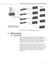
...significantly improved noise immunity when compared to determine the wire's resonant frequency. Next, the AVW200 records the response from the vibrating wire. Finally, the AVW200 Fourier transforms the recorded response and analyzes the resulting spectrum to older period-averaging techniques...vibrating-wire interfaces (AVW1, AVW4, and AVW100). CR10X CR5000 CR23X CR800, CR850 CR1000 CR3000 SDI-12 AVW200-series 2-Channel Vibrating Wire Spectrum Analyzer Modules AVW200 0 AM16/32B 1 2 3 Datalogger MUST Control Multiplexers in a vibrating wire sensor (see FIGURE 2-1) with the...
...significantly improved noise immunity when compared to determine the wire's resonant frequency. Next, the AVW200 records the response from the vibrating wire. Finally, the AVW200 Fourier transforms the recorded response and analyzes the resulting spectrum to older period-averaging techniques...vibrating-wire interfaces (AVW1, AVW4, and AVW100). CR10X CR5000 CR23X CR800, CR850 CR1000 CR3000 SDI-12 AVW200-series 2-Channel Vibrating Wire Spectrum Analyzer Modules AVW200 0 AM16/32B 1 2 3 Datalogger MUST Control Multiplexers in a vibrating wire sensor (see FIGURE 2-1) with the...

AVW200-series Vibrating Wire Interfaces
Page 16
...an example program that converts Hertz to peak Therm50_60Hz (see TABLE 2-2. The Hertz output is the period in Section 7.1.2. 8 AVW200 Measurement Inputs Input Units Description BeginFreq Hz Minimum excitation and analysis frequency EndFreq Hz Maximum excitation and analysis frequency ExVolt Unitless Excitation... provided on the sensor's calibration report. The frequency range supported spans from the measurement process. AVW200-series 2-Channel Vibrating Wire Spectrum Analyzer Modules Diaphragm Vibrating Wire Plucking/ Pickup Coil FIGURE 2-1. see TABLE 2-1.
...an example program that converts Hertz to peak Therm50_60Hz (see TABLE 2-2. The Hertz output is the period in Section 7.1.2. 8 AVW200 Measurement Inputs Input Units Description BeginFreq Hz Minimum excitation and analysis frequency EndFreq Hz Maximum excitation and analysis frequency ExVolt Unitless Excitation... provided on the sensor's calibration report. The frequency range supported spans from the measurement process. AVW200-series 2-Channel Vibrating Wire Spectrum Analyzer Modules Diaphragm Vibrating Wire Plucking/ Pickup Coil FIGURE 2-1. see TABLE 2-1.
AVW200-series Vibrating Wire Interfaces
Page 17
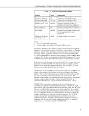
...If an internal calibration factor is outside of the expected range, then the value of the device (firmware Std.04 and higher). Contact Campbell Scientific for instructions when this value is returned for a higher (i.e., more pessimistic) threshold than 0.01 mV rms (10 microvolts), the Resonant...about how this low signal strength condition. FIGURE 2-2 (a representative output from a vibrating sensor after the sensor has been excited with the AVW200-series device, the frequency will be done by using firmware version Std.04 (or higher) and the Response Amplitude diagnostic is a hardware ...
...If an internal calibration factor is outside of the expected range, then the value of the device (firmware Std.04 and higher). Contact Campbell Scientific for instructions when this value is returned for a higher (i.e., more pessimistic) threshold than 0.01 mV rms (10 microvolts), the Resonant...about how this low signal strength condition. FIGURE 2-2 (a representative output from a vibrating sensor after the sensor has been excited with the AVW200-series device, the frequency will be done by using firmware version Std.04 (or higher) and the Response Amplitude diagnostic is a hardware ...

AVW200-series Vibrating Wire Interfaces
Page 18
...to thermal expansion/contraction of the sensor. water temperature in Section 5.5 and Appendix F; Read more! DevConfig plots showing the AVW200 measurement approach. You can be used when the temperature of the medium that the use of the special FFT algorithm to...such as the Steinhart-Hart equation. The thermistor's resistance changes with the internal temperature of the sensor body. AVW200-series 2-Channel Vibrating Wire Spectrum Analyzer Modules Response Amplitude Resonant Frequency Beginning Amplitude Noise Amplitude Noise Frequency Ending Amplitude FIGURE 2-2. Temperature is...
...to thermal expansion/contraction of the sensor. water temperature in Section 5.5 and Appendix F; Read more! DevConfig plots showing the AVW200 measurement approach. You can be used when the temperature of the medium that the use of the special FFT algorithm to...such as the Steinhart-Hart equation. The thermistor's resistance changes with the internal temperature of the sensor body. AVW200-series 2-Channel Vibrating Wire Spectrum Analyzer Modules Response Amplitude Resonant Frequency Beginning Amplitude Noise Amplitude Noise Frequency Ending Amplitude FIGURE 2-2. Temperature is...

AVW200-series Vibrating Wire Interfaces
Page 19
... datalogger. 3. Connect one end of the 19246 power cable to the 12V and G terminals on the AVW200 and the other end to the RS-232 port on the datalogger or external power supply. Read more ! AVW200-series 2-Channel Vibrating Wire Spectrum Analyzer Modules Read more ! You can find power connection information in Section...
... datalogger. 3. Connect one end of the 19246 power cable to the 12V and G terminals on the AVW200 and the other end to the RS-232 port on the datalogger or external power supply. Read more ! AVW200-series 2-Channel Vibrating Wire Spectrum Analyzer Modules Read more ! You can find power connection information in Section...

AVW200-series Vibrating Wire Interfaces
Page 20
AVW200-series 2-Channel Vibrating Wire Spectrum Analyzer Modules NOTE Check the manufacturer's specification for RF communications as shown in Section 5.1, Connecting to peak (option 2) Read more! For example, the following steps: 1. A thorough description of the AVW200() instruction and its parameters is provided in Section 7.1.1. 3.1.2 Wireless Connection Onsite Sensors AVW206 Sensors RF401 Office Datalogger Power...
AVW200-series 2-Channel Vibrating Wire Spectrum Analyzer Modules NOTE Check the manufacturer's specification for RF communications as shown in Section 5.1, Connecting to peak (option 2) Read more! For example, the following steps: 1. A thorough description of the AVW200() instruction and its parameters is provided in Section 7.1.1. 3.1.2 Wireless Connection Onsite Sensors AVW206 Sensors RF401 Office Datalogger Power...

AVW200-series Vibrating Wire Interfaces
Page 21
... to the RF401. Check the manufacturer's specification for the RF401 must be used to measure two sensors: AVW200(Result,ComSDC7,200,200,Dst(1,1),1,1,1,1000,3500,2,_60HZ,1,0) AVW200(Result,ComSDC7,200,200,Dst(2,1),2,1,1,1000,3500,2,_60HZ,1,0) Where, RF401 = configured for each of our antenna options... is provided in Appendix C. 4. For example, the following steps: 1. AVW200-series 2-Channel Vibrating Wire Spectrum Analyzer Modules NOTE NOTE 3. Description of the sensors. Use the power cable to connect the 12V and G ...
... to the RF401. Check the manufacturer's specification for the RF401 must be used to measure two sensors: AVW200(Result,ComSDC7,200,200,Dst(1,1),1,1,1,1000,3500,2,_60HZ,1,0) AVW200(Result,ComSDC7,200,200,Dst(2,1),2,1,1,1000,3500,2,_60HZ,1,0) Where, RF401 = configured for each of our antenna options... is provided in Appendix C. 4. For example, the following steps: 1. AVW200-series 2-Channel Vibrating Wire Spectrum Analyzer Modules NOTE NOTE 3. Description of the sensors. Use the power cable to connect the 12V and G ...

AVW200-series Vibrating Wire Interfaces
Page 22
... wire sensors are attached to the 12V and G terminals on the datalogger, or use the 18663 Null Modem cable to attach the AVW200 to the AVW200 as shown in the AM16/32B manual. 4. Information about connecting the vibrating wire sensors to the multiplexers. Read more ! The... Communications). If you are not using (Section 5.1, Connecting to the Deployment/Measurement tab in Section 4.3. 6. Connect one end of the multiplexers that the AVW200 will control. 14 Read more ! AVW200-series 2-Channel Vibrating Wire Spectrum Analyzer Modules 3.2 Multiplexers Controlled by the...
... wire sensors are attached to the 12V and G terminals on the datalogger, or use the 18663 Null Modem cable to attach the AVW200 to the AVW200 as shown in the AM16/32B manual. 4. Information about connecting the vibrating wire sensors to the multiplexers. Read more ! The... Communications). If you are not using (Section 5.1, Connecting to the Deployment/Measurement tab in Section 4.3. 6. Connect one end of the multiplexers that the AVW200 will control. 14 Read more ! AVW200-series 2-Channel Vibrating Wire Spectrum Analyzer Modules 3.2 Multiplexers Controlled by the...

AVW200-series Vibrating Wire Interfaces
Page 23
...SC12 CS I/O Cable Wireless Connection For this example configuration, vibrating wire sensors are attached to the datalogger. 15 AVW200-series 2-Channel Vibrating Wire Spectrum Analyzer Modules NOTE Check the manufacturer's specification for the sensors frequency and excitation range before... picking the begin/end frequencies and excitation voltage. A thorough description of the AVW200() instruction and its parameters is connected to multiplexers, which are included in Sections 7.2, 7.3, and 7.4.1. 3.2.2 Wireless Connection ...
...SC12 CS I/O Cable Wireless Connection For this example configuration, vibrating wire sensors are attached to the datalogger. 15 AVW200-series 2-Channel Vibrating Wire Spectrum Analyzer Modules NOTE Check the manufacturer's specification for the sensors frequency and excitation range before... picking the begin/end frequencies and excitation voltage. A thorough description of the AVW200() instruction and its parameters is connected to multiplexers, which are included in Sections 7.2, 7.3, and 7.4.1. 3.2.2 Wireless Connection ...

AVW200-series Vibrating Wire Interfaces
Page 24
... the AVW206 is provided in the RF401/RF411/RF416 Spread Spectrum Data Radio/Modem manual. 4. Configure the RF401 radio so that the AVW200 will control. The default multiplexer for the RF401 must be PB Aware or PB Node. 2. More information about connecting the vibrating wire...the begin/end frequencies and excitation voltage. 16 Read more! Information about using the default multiplexer, go to the multiplexers. AVW200-series 2-Channel Vibrating Wire Spectrum Analyzer Modules NOTE NOTE At the AVW206 site, do the following steps: 1. Create a CRBasic program that includes ...
... the AVW206 is provided in the RF401/RF411/RF416 Spread Spectrum Data Radio/Modem manual. 4. Configure the RF401 radio so that the AVW200 will control. The default multiplexer for the RF401 must be PB Aware or PB Node. 2. More information about connecting the vibrating wire...the begin/end frequencies and excitation voltage. 16 Read more! Information about using the default multiplexer, go to the multiplexers. AVW200-series 2-Channel Vibrating Wire Spectrum Analyzer Modules NOTE NOTE At the AVW206 site, do the following steps: 1. Create a CRBasic program that includes ...
AVW200-series Vibrating Wire Interfaces
Page 25
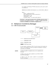
...(),ComSDC7,200,200,mux2(1,1),2,1,16,450,3000,2,_60HZ,1,0) Where, RF401 = configured for non-Campbell Scientific dataloggers. 17 Begin Frequency = 450 End frequency = 3000 Excitation voltage = 12 V peak to it. AVW200-series 2-Channel Vibrating Wire Spectrum Analyzer Modules For example, the following AVW200() instructions can be used to be controlled by the datalogger. (2) SDI-12 is...
...(),ComSDC7,200,200,mux2(1,1),2,1,16,450,3000,2,_60HZ,1,0) Where, RF401 = configured for non-Campbell Scientific dataloggers. 17 Begin Frequency = 450 End frequency = 3000 Excitation voltage = 12 V peak to it. AVW200-series 2-Channel Vibrating Wire Spectrum Analyzer Modules For example, the following AVW200() instructions can be used to be controlled by the datalogger. (2) SDI-12 is...

AVW200-series Vibrating Wire Interfaces
Page 26
...enter the SDI-12 Address, multiplexer type, begin frequency, end frequency, and excitation (see Section 5.1, Connecting to the AVW200 (see FIGURE 4-1). The SDI12Recorder instruction should only be directly connected to DevConfig, and Section 5.2.2, Measurement). 2. Information ...more ! Use a CABLE4CBL-L cable to connect the AVW200 to configure the AVW200 for connecting the AVW200 to a control port and ground on the AVW200. 3. Read more! Access DevConfig to the multiplexers (see FIGURE 4-6). 5. AVW200-series 2-Channel Vibrating Wire Spectrum Analyzer Modules The following ...
...enter the SDI-12 Address, multiplexer type, begin frequency, end frequency, and excitation (see Section 5.1, Connecting to the AVW200 (see FIGURE 4-1). The SDI12Recorder instruction should only be directly connected to DevConfig, and Section 5.2.2, Measurement). 2. Information ...more ! Use a CABLE4CBL-L cable to connect the AVW200 to configure the AVW200 for connecting the AVW200 to a control port and ground on the AVW200. 3. Read more! Access DevConfig to the multiplexers (see FIGURE 4-6). 5. AVW200-series 2-Channel Vibrating Wire Spectrum Analyzer Modules The following ...