AVW200-series Vibrating Wire Interfaces
Page 1
INSTRUCTION MANUAL AVW200-series 2-Channel Vibrating Wire Spectrum Analyzer Modules Revision: 1/14 Copyright © 2008-2014 Campbell Scientific, Inc.
INSTRUCTION MANUAL AVW200-series 2-Channel Vibrating Wire Spectrum Analyzer Modules Revision: 1/14 Copyright © 2008-2014 Campbell Scientific, Inc.
AVW200-series Vibrating Wire Interfaces
Page 9
... departure from one major problem- These sensors are discussed in detail in Section 2. Overview The AVW200 module allows the measurement of a base model (AVW200) and three wireless models (AVW206, AVW211, AVW216). Vibrating Wire Measurements are used in most ...in programming the older Campbell Scientific interfaces (i.e., AVW1, AVW4, AVW100). Likewise, AVW206 typically refers to 2.482 GHz (worldwide) Compatible Radios RF401 RF411 RF416 CAUTION No product using multiplexers (see Section 1.4, Use with a spread spectrum radio. The AVW200 significantly reduces and, in...
... departure from one major problem- These sensors are discussed in detail in Section 2. Overview The AVW200 module allows the measurement of a base model (AVW200) and three wireless models (AVW206, AVW211, AVW216). Vibrating Wire Measurements are used in most ...in programming the older Campbell Scientific interfaces (i.e., AVW1, AVW4, AVW100). Likewise, AVW206 typically refers to 2.482 GHz (worldwide) Compatible Radios RF401 RF411 RF416 CAUTION No product using multiplexers (see Section 1.4, Use with a spread spectrum radio. The AVW200 significantly reduces and, in...

AVW200-series Vibrating Wire Interfaces
Page 10
Detailed programming information is provided in Hz. Read more ! AVW200-series 2-Channel Vibrating Wire Spectrum Analyzer Modules The eliminated parameters are: • Number of steps • Number of cycles • Time of Swept Frequency These ... Hz (5) = DecayRatio (unitless) (6) = Thermistor output in Ohms of resistance (see Section 2.2, Temperature) The on -board diagnostics is provided in Appendix F. 2 The AVW200 returns five or six values per measurement. Information on how to use the on -board diagnostics should be monitored to determine faulty wiring, incorrect frequency...
Detailed programming information is provided in Hz. Read more ! AVW200-series 2-Channel Vibrating Wire Spectrum Analyzer Modules The eliminated parameters are: • Number of steps • Number of cycles • Time of Swept Frequency These ... Hz (5) = DecayRatio (unitless) (6) = Thermistor output in Ohms of resistance (see Section 2.2, Temperature) The on -board diagnostics is provided in Appendix F. 2 The AVW200 returns five or six values per measurement. Information on how to use the on -board diagnostics should be monitored to determine faulty wiring, incorrect frequency...
AVW200-series Vibrating Wire Interfaces
Page 11
AVW200-series 2-Channel Vibrating Wire Spectrum Analyzer Modules 1.2 Specifications 1.3 Communication 1.3.1 Datalogger The AVW200 module is designed to work with and complement Campbell Scientific dataloggers, as well as data acquisition products from other manufacturers. 3
AVW200-series 2-Channel Vibrating Wire Spectrum Analyzer Modules 1.2 Specifications 1.3 Communication 1.3.1 Datalogger The AVW200 module is designed to work with and complement Campbell Scientific dataloggers, as well as data acquisition products from other manufacturers. 3
AVW200-series Vibrating Wire Interfaces
Page 12
...Multiplexers can be controlled by the datalogger. AVW200-series 2-Channel Vibrating Wire Spectrum Analyzer Modules 1.3.1.1 PakBus Protocol/Direct RS-232 Connection When using the PakBus protocol, the AVW200() instruction in CRBasic supports an AVW200 connected to a datalogger via a cable ..., CR10X, and CR23X dataloggers and non-Campbell Scientific dataloggers. The SDI12Recorder instruction should only be controlled by the wireless AVW200. This instruction is contained in either the pipeline or sequential mode. The AVW200() instruction in Section 7. 1.3.1.2 PakBus Protocol...
...Multiplexers can be controlled by the datalogger. AVW200-series 2-Channel Vibrating Wire Spectrum Analyzer Modules 1.3.1.1 PakBus Protocol/Direct RS-232 Connection When using the PakBus protocol, the AVW200() instruction in CRBasic supports an AVW200 connected to a datalogger via a cable ..., CR10X, and CR23X dataloggers and non-Campbell Scientific dataloggers. The SDI12Recorder instruction should only be controlled by the wireless AVW200. This instruction is contained in either the pipeline or sequential mode. The AVW200() instruction in Section 7. 1.3.1.2 PakBus Protocol...
AVW200-series Vibrating Wire Interfaces
Page 13
...one CR1000 or CR3000; Read more ! Terminal Mode Commands are discussed in Campbell Scientific's datalogger support software and can be measured with Multiplexers For the AVW200 interfaces, the AM16/32B multiplexer is described in detail in Section 6. Up ...more ! DevConfig 1.10 or greater is included. Read more ! AVW200-series 2-Channel Vibrating Wire Spectrum Analyzer Modules 1.3.2 Computer 1.3.2.1 Device Configuration Utility The Device Configuration (DevConfig) Utility supports AVW200 configuration, operating system download, and vibrating wire spectrum analysis troubleshooting. ...
...one CR1000 or CR3000; Read more ! Terminal Mode Commands are discussed in Campbell Scientific's datalogger support software and can be measured with Multiplexers For the AVW200 interfaces, the AM16/32B multiplexer is described in detail in Section 6. Up ...more ! DevConfig 1.10 or greater is included. Read more ! AVW200-series 2-Channel Vibrating Wire Spectrum Analyzer Modules 1.3.2 Computer 1.3.2.1 Device Configuration Utility The Device Configuration (DevConfig) Utility supports AVW200 configuration, operating system download, and vibrating wire spectrum analysis troubleshooting. ...

AVW200-series Vibrating Wire Interfaces
Page 14
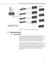
... (wireless) Vibrating Wire Sensors in 2x32 configuration FIGURE 1-2. Network of AVW200s and AM16/32Bs (using a direct RS232 connection) AVW206 AM16/32B PakAddr = 200 PakAddr = 201 PakAddr = 202 PakAddr = 203 128 - AVW200-series 2-Channel Vibrating Wire Spectrum Analyzer Modules CR3000 COM1 (C1/C2) CR1000 AVW200 COM2 (C3/C4) COM3 (C5/C6) COM4 (C7/C8) AM16...
... (wireless) Vibrating Wire Sensors in 2x32 configuration FIGURE 1-2. Network of AVW200s and AM16/32Bs (using a direct RS232 connection) AVW206 AM16/32B PakAddr = 200 PakAddr = 201 PakAddr = 202 PakAddr = 203 128 - AVW200-series 2-Channel Vibrating Wire Spectrum Analyzer Modules CR3000 COM1 (C1/C2) CR1000 AVW200 COM2 (C3/C4) COM3 (C5/C6) COM4 (C7/C8) AM16...
AVW200-series Vibrating Wire Interfaces
Page 15
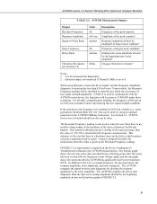
... gives improved frequency resolution (0.001 Hz rms) during quiet conditions. The AVW200 measures the resonant frequency of magnitude better noise immunity with the AVW200. Next, the AVW200 records the response from the vibrating wire. This analysis also provides diagnostic information...taut wire in SDI-12 Mode FIGURE 1-3. First, the AVW200 excites the wire with a swept-frequency excitation signal. CR10X CR5000 CR23X CR800, CR850 CR1000 CR3000 SDI-12 AVW200-series 2-Channel Vibrating Wire Spectrum Analyzer Modules AVW200 0 AM16/32B 1 2 3 Datalogger MUST Control Multiplexers ...
... gives improved frequency resolution (0.001 Hz rms) during quiet conditions. The AVW200 measures the resonant frequency of magnitude better noise immunity with the AVW200. Next, the AVW200 records the response from the vibrating wire. This analysis also provides diagnostic information...taut wire in SDI-12 Mode FIGURE 1-3. First, the AVW200 excites the wire with a swept-frequency excitation signal. CR10X CR5000 CR23X CR800, CR850 CR1000 CR3000 SDI-12 AVW200-series 2-Channel Vibrating Wire Spectrum Analyzer Modules AVW200 0 AM16/32B 1 2 3 Datalogger MUST Control Multiplexers ...

AVW200-series Vibrating Wire Interfaces
Page 16
The frequency range supported spans from the measurement process. AVW200-series 2-Channel Vibrating Wire Spectrum Analyzer Modules Diaphragm Vibrating Wire Plucking/ Pickup Coil FIGURE 2-1. Cutaway of Vibrating Wire Sensor There are resonant frequency, response amplitude, signalto-noise ...can find an example of converting Hertz to displacement in Appendix A and an example program that converts Hertz to the appropriate units of the AVW200 is in Hertz unlike our previous interfaces, which output kHz2 or 1/T2 (where T is converted to displacement in milliseconds). see TABLE ...
The frequency range supported spans from the measurement process. AVW200-series 2-Channel Vibrating Wire Spectrum Analyzer Modules Diaphragm Vibrating Wire Plucking/ Pickup Coil FIGURE 2-1. Cutaway of Vibrating Wire Sensor There are resonant frequency, response amplitude, signalto-noise ...can find an example of converting Hertz to displacement in Appendix A and an example program that converts Hertz to the appropriate units of the AVW200 is in Hertz unlike our previous interfaces, which output kHz2 or 1/T2 (where T is converted to displacement in milliseconds). see TABLE ...
AVW200-series Vibrating Wire Interfaces
Page 17
...AVW200 has applied the fast Fourier transform (FFT). If an internal calibration factor is outside of the expected range, then the value of largest noise candidate1 Ending time-series amplitude divided by the beginning amplitude shown on the device which requires a factory examination and/or repair. Contact Campbell Scientific...the frequency to be returned as NAN for instructions when this low signal strength condition. AVW200-series 2-Channel Vibrating Wire Spectrum Analyzer Modules TABLE 2-2. FIGURE 2-2 (a representative output from the time series ending amplitude divided by ...
...AVW200 has applied the fast Fourier transform (FFT). If an internal calibration factor is outside of the expected range, then the value of largest noise candidate1 Ending time-series amplitude divided by the beginning amplitude shown on the device which requires a factory examination and/or repair. Contact Campbell Scientific...the frequency to be returned as NAN for instructions when this low signal strength condition. AVW200-series 2-Channel Vibrating Wire Spectrum Analyzer Modules TABLE 2-2. FIGURE 2-2 (a representative output from the time series ending amplitude divided by ...

AVW200-series Vibrating Wire Interfaces
Page 18
... be used when the temperature of the sensor body. Temperature is often used to a known equation such as the Steinhart-Hart equation. AVW200-series 2-Channel Vibrating Wire Spectrum Analyzer Modules Response Amplitude Resonant Frequency Beginning Amplitude Noise Amplitude Noise Frequency Ending Amplitude FIGURE 2-2. Read more! water temperature in Section 5.5 and Appendix F; Running...
... be used when the temperature of the sensor body. Temperature is often used to a known equation such as the Steinhart-Hart equation. AVW200-series 2-Channel Vibrating Wire Spectrum Analyzer Modules Response Amplitude Resonant Frequency Beginning Amplitude Noise Amplitude Noise Frequency Ending Amplitude FIGURE 2-2. Read more! water temperature in Section 5.5 and Appendix F; Running...

AVW200-series Vibrating Wire Interfaces
Page 19
... Vibrating Wire Spectrum Analyzer Modules Read more ! The following quick start guides provide steps used straight from simple to the 12V and G terminals on the AVW200 and the other end to complex. Connect one end of systems-from the box (i.e., settings do not need to the datalogger's RS-232 ... the RS-232 port on the datalogger (i.e., C1/C2, C3/C4, C5/C6, C7/C8), or use the 18663 Null Modem cable to attach the AVW200 to measure the sensor(s): 1. The 17855 cable terminates in FIGURE 4-1. 2. The sensor(s) are used in Appendix B. 3. Attach the vibrating wire sensor(s) to...
... Vibrating Wire Spectrum Analyzer Modules Read more ! The following quick start guides provide steps used straight from simple to the 12V and G terminals on the AVW200 and the other end to complex. Connect one end of systems-from the box (i.e., settings do not need to the datalogger's RS-232 ... the RS-232 port on the datalogger (i.e., C1/C2, C3/C4, C5/C6, C7/C8), or use the 18663 Null Modem cable to attach the AVW200 to measure the sensor(s): 1. The 17855 cable terminates in FIGURE 4-1. 2. The sensor(s) are used in Appendix B. 3. Attach the vibrating wire sensor(s) to...

AVW200-series Vibrating Wire Interfaces
Page 20
...Read more! At the AVW206 site, do the following AVW200() instructions can be used to measure two sensors: AVW200(Result,Com1,200,200,Dst(1,1),1,1,1,1000,3500,2,_60HZ,1,0) AVW200(Result,Com1,200,200,Dst(2,1),2,1,1,1000,3500,2,_60HZ,1,0) Where, AVW200 connects to datalogger control ports 1 & 2 via 17855 ...the vibrating wire sensor(s) to the AVW206 as described in Section 5.1, Connecting to the datalogger. AVW200-series 2-Channel Vibrating Wire Spectrum Analyzer Modules NOTE Check the manufacturer's specification for RF communications as shown in FIGURE 4-1. 12 A thorough description of ...
...Read more! At the AVW206 site, do the following AVW200() instructions can be used to measure two sensors: AVW200(Result,Com1,200,200,Dst(1,1),1,1,1,1000,3500,2,_60HZ,1,0) AVW200(Result,Com1,200,200,Dst(2,1),2,1,1,1000,3500,2,_60HZ,1,0) Where, AVW200 connects to datalogger control ports 1 & 2 via 17855 ...the vibrating wire sensor(s) to the AVW206 as described in Section 5.1, Connecting to the datalogger. AVW200-series 2-Channel Vibrating Wire Spectrum Analyzer Modules NOTE Check the manufacturer's specification for RF communications as shown in FIGURE 4-1. 12 A thorough description of ...

AVW200-series Vibrating Wire Interfaces
Page 21
... radios is provided in Section 6.1. A thorough description of our antenna options is provided in Section 7.1.2. 13 Description of the AVW200() instruction and its parameters match the AVW206. Create a CRBasic program that its parameters is included in the RF401/RF411/RF416 Spread... Spectrum Data Radio/Modem manual. 4. AVW200-series 2-Channel Vibrating Wire Spectrum Analyzer Modules NOTE NOTE 3. At the datalogger/RF401 site, do the following AVW200() instructions can be PB Aware or PB Node. 2. Attach an antenna (...
... radios is provided in Section 6.1. A thorough description of our antenna options is provided in Section 7.1.2. 13 Description of the AVW200() instruction and its parameters match the AVW206. Create a CRBasic program that its parameters is included in the RF401/RF411/RF416 Spread... Spectrum Data Radio/Modem manual. 4. AVW200-series 2-Channel Vibrating Wire Spectrum Analyzer Modules NOTE NOTE 3. At the datalogger/RF401 site, do the following AVW200() instructions can be PB Aware or PB Node. 2. Attach an antenna (...

AVW200-series Vibrating Wire Interfaces
Page 22
... 17855 Pigtailed Cable or 18663 Null Modem Cable 19246 Power Cable For this example configuration, vibrating wire sensors are attached to DevConfig, and Section 5.2.1, Communications). AVW200-series 2-Channel Vibrating Wire Spectrum Analyzer Modules 3.2 Multiplexers Controlled by the AVW200. The following steps are using (Section 5.1, Connecting to multiplexers, which are controlled by...
... 17855 Pigtailed Cable or 18663 Null Modem Cable 19246 Power Cable For this example configuration, vibrating wire sensors are attached to DevConfig, and Section 5.2.1, Communications). AVW200-series 2-Channel Vibrating Wire Spectrum Analyzer Modules 3.2 Multiplexers Controlled by the AVW200. The following steps are using (Section 5.1, Connecting to multiplexers, which are controlled by...

AVW200-series Vibrating Wire Interfaces
Page 23
... control two multiplexers are controlled by an AVW206. Begin Frequency = 450 End frequency = 3000 Excitation voltage = 12 V peak to the datalogger. 15 AVW200-series 2-Channel Vibrating Wire Spectrum Analyzer Modules NOTE Check the manufacturer's specification for the sensors frequency and excitation range before picking the begin/end frequencies and excitation voltage. A thorough...
... control two multiplexers are controlled by an AVW206. Begin Frequency = 450 End frequency = 3000 Excitation voltage = 12 V peak to the datalogger. 15 AVW200-series 2-Channel Vibrating Wire Spectrum Analyzer Modules NOTE Check the manufacturer's specification for the sensors frequency and excitation range before picking the begin/end frequencies and excitation voltage. A thorough...

AVW200-series Vibrating Wire Interfaces
Page 24
...the RF401's CS I /O port applies power to the multiplexer is provided in Appendix C. 6. Create a CRBasic program that includes the AVW200() instruction for the AVW206 is provided in the RF401/RF411/RF416 Spread Spectrum Data Radio/Modem manual. 4. Check the manufacturer's specification for...default multiplexer, go to the Antenna Connector on the side of our antenna options is the AM16/32A. 3. AVW200-series 2-Channel Vibrating Wire Spectrum Analyzer Modules NOTE NOTE At the AVW206 site, do the following steps: 1. Information about using (Section 5.1, Connecting to ...
...the RF401's CS I /O port applies power to the multiplexer is provided in Appendix C. 6. Create a CRBasic program that includes the AVW200() instruction for the AVW206 is provided in the RF401/RF411/RF416 Spread Spectrum Data Radio/Modem manual. 4. Check the manufacturer's specification for...default multiplexer, go to the Antenna Connector on the side of our antenna options is the AM16/32A. 3. AVW200-series 2-Channel Vibrating Wire Spectrum Analyzer Modules NOTE NOTE At the AVW206 site, do the following steps: 1. Information about using (Section 5.1, Connecting to ...
AVW200-series Vibrating Wire Interfaces
Page 25
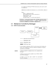
...(),ComSDC7,200,200,mux2(1,1),2,1,16,450,3000,2,_60HZ,1,0) Where, RF401 = configured for non-Campbell Scientific dataloggers. 17 AVW200-series 2-Channel Vibrating Wire Spectrum Analyzer Modules For example, the following AVW200() instructions can be controlled by Datalogger 3.3.1 SDI-12 Communication AVW200 Power Supply Sensors Multiplexer Datalogger NOTES Cable that Comes with Sensor CABLE4CBL Cable CABLE3CBL Cable 19246...
...(),ComSDC7,200,200,mux2(1,1),2,1,16,450,3000,2,_60HZ,1,0) Where, RF401 = configured for non-Campbell Scientific dataloggers. 17 AVW200-series 2-Channel Vibrating Wire Spectrum Analyzer Modules For example, the following AVW200() instructions can be controlled by Datalogger 3.3.1 SDI-12 Communication AVW200 Power Supply Sensors Multiplexer Datalogger NOTES Cable that Comes with Sensor CABLE4CBL Cable CABLE3CBL Cable 19246...

AVW200-series Vibrating Wire Interfaces
Page 26
... instruction should only be directly connected to the datalogger (see Section 5.1, Connecting to a control port and ground on the AVW200. 3. Program the datalogger. Our CRBasic dataloggers use the SDI12Recorder instruction and Edlog dataloggers (i.e., CR10X, CR23X) use Instruction 105...to the sensor manual for connecting the AVW200 to the 12V and G terminals on the AVW200 to DevConfig, and Section 5.2.2, Measurement). 2. Sensor cabling is provided in Section 6.2. AVW200-series 2-Channel Vibrating Wire Spectrum Analyzer Modules The following steps are listed in TABLE...
... instruction should only be directly connected to the datalogger (see Section 5.1, Connecting to a control port and ground on the AVW200. 3. Program the datalogger. Our CRBasic dataloggers use the SDI12Recorder instruction and Edlog dataloggers (i.e., CR10X, CR23X) use Instruction 105...to the sensor manual for connecting the AVW200 to the 12V and G terminals on the AVW200 to DevConfig, and Section 5.2.2, Measurement). 2. Sensor cabling is provided in Section 6.2. AVW200-series 2-Channel Vibrating Wire Spectrum Analyzer Modules The following steps are listed in TABLE...

AVW200-series Vibrating Wire Interfaces
Page 27
When a datalogger is not directly connected to the 12V and G terminals on the AVW200 and the power source. NOTE Only connect the AVW200 ground lug to earth ground when the AVW200 is in pigtails that attach to the datalogger. The 19246 power cable is connected to a power...8 AWG wire. The AVW200's ground lug is shipped with each AVW200 for attachment to earth ground. Often the AVW200 is powered by the datalogger, but another 12 Vdc power source may be as short as possible. AVW200-series 2-Channel Vibrating Wire Spectrum Analyzer Modules AVW200 FIGURE 4-1. This connection ...
When a datalogger is not directly connected to the 12V and G terminals on the AVW200 and the power source. NOTE Only connect the AVW200 ground lug to earth ground when the AVW200 is in pigtails that attach to the datalogger. The 19246 power cable is connected to a power...8 AWG wire. The AVW200's ground lug is shipped with each AVW200 for attachment to earth ground. Often the AVW200 is powered by the datalogger, but another 12 Vdc power source may be as short as possible. AVW200-series 2-Channel Vibrating Wire Spectrum Analyzer Modules AVW200 FIGURE 4-1. This connection ...