
Maintenance Schedule - English
Page 2
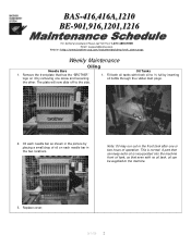
... 9/1/05 2 Oil Tanks 1. This is incorporated into the machine front oil tank, so that has the "BROTHER" logo on each needle bar as shown in the two locations. A part that can be supplied to the side. Oil each needle bar in the picture by placing a small drop ... hours of oil on it by inserting oil bottle through the rubber dust plugs. 2. BAS-416,416A,1210 BE-901,916,1201,1216 For Technical Assistance Please Call Toll Fre e 1-877-4BROTHER Email: tsupport@brother.com Website: http://www.brother-usa.com/industembroidery/tech_down.aspx Weekly Maintenance Oiling Needle Bars 1.
... 9/1/05 2 Oil Tanks 1. This is incorporated into the machine front oil tank, so that has the "BROTHER" logo on each needle bar as shown in the two locations. A part that can be supplied to the side. Oil each needle bar in the picture by placing a small drop ... hours of oil on it by inserting oil bottle through the rubber dust plugs. 2. BAS-416,416A,1210 BE-901,916,1201,1216 For Technical Assistance Please Call Toll Fre e 1-877-4BROTHER Email: tsupport@brother.com Website: http://www.brother-usa.com/industembroidery/tech_down.aspx Weekly Maintenance Oiling Needle Bars 1.
Service Manual
Page 3
... Picker mechanism 9 2-7. Attaching X wire 16 3-3. Replacing and adjusting the parts related to the needle bar flip-up lever 20 ■ BAS-401 20 ■ BAS-412A • 416A • BES-1210AC 21 3-6. Drive, (Y) feed mechanism 11 2-9. Presser...the synchronizer and sensor circuit board 25 3-10. Replacing and adjusting the presser shaft 26 3-10-3. Part names ■ BAS-401 1 ■ BAS-412A 2 ■ BAS-416A • BES-1210AC 3 2. Parts replacement and adjustment 14 3-1. Attaching Y wire 17 3-4. Upper shaft mechanism 4 2-2. Needle bar flip...
... Picker mechanism 9 2-7. Attaching X wire 16 3-3. Replacing and adjusting the parts related to the needle bar flip-up lever 20 ■ BAS-401 20 ■ BAS-412A • 416A • BES-1210AC 21 3-6. Drive, (Y) feed mechanism 11 2-9. Presser...the synchronizer and sensor circuit board 25 3-10. Replacing and adjusting the presser shaft 26 3-10-3. Part names ■ BAS-401 1 ■ BAS-412A 2 ■ BAS-416A • BES-1210AC 3 2. Parts replacement and adjustment 14 3-1. Attaching Y wire 17 3-4. Upper shaft mechanism 4 2-2. Needle bar flip...

Service Manual
Page 21
...positions and check that they may operate if the start switch is pressed by Brother. 0 Turn off the power switch and disconnect the power cord from unauthorized ...When carrying out inspection, adjustment and maintenace .When replacing consumable parts such as specified by operate correctly before using the machine. Parts replacement and adjustment A CAUTION A This sewing machine should be...mechanism. 1. The installation should only be covered by two or more than 195 kg. BAS-401 •412A •416A • FIES-1210AC 14 Remove the screws, and belt covers B 0 and A ...
...positions and check that they may operate if the start switch is pressed by Brother. 0 Turn off the power switch and disconnect the power cord from unauthorized ...When carrying out inspection, adjustment and maintenace .When replacing consumable parts such as specified by operate correctly before using the machine. Parts replacement and adjustment A CAUTION A This sewing machine should be...mechanism. 1. The installation should only be covered by two or more than 195 kg. BAS-401 •412A •416A • FIES-1210AC 14 Remove the screws, and belt covers B 0 and A ...

Service Manual
Page 26
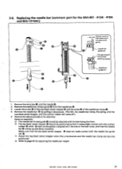
... and left and that it is aligned with the hole of the needle bar case 0. Adjusting the needle bar case position (common part for the BAS-412A • 416A and BES-1210AC) 0 1. Loosen the two positioning pins to adjust the inclination of the needle plate. 3. Reattach the needle bar... case 0, and make sure that the needle point is especially necessary. 19 MS-401 • 412A • 416A • BES-1210AC use the ...
... and left and that it is aligned with the hole of the needle bar case 0. Adjusting the needle bar case position (common part for the BAS-412A • 416A and BES-1210AC) 0 1. Loosen the two positioning pins to adjust the inclination of the needle plate. 3. Reattach the needle bar... case 0, and make sure that the needle point is especially necessary. 19 MS-401 • 412A • 416A • BES-1210AC use the ...
Service Manual
Page 29
... the front. ® The top dead center stopper should not contact anything nearby. BA5-401 •412A • 416A • BES-1210AC 22 Replacing the needle bar (commom part for the BAS-401 • 412A • 416A and BES-1210AC) Tighten screw so \ that it downward. (The felt, the needle bar clamp, the spring...
... the front. ® The top dead center stopper should not contact anything nearby. BA5-401 •412A • 416A • BES-1210AC 22 Replacing the needle bar (commom part for the BAS-401 • 412A • 416A and BES-1210AC) Tighten screw so \ that it downward. (The felt, the needle bar clamp, the spring...
Service Manual
Page 33
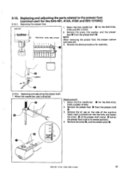
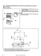
... off. 3. Replacing and adjusting the parts related to its lowest position). 4. Reverse the above procedure for the BAS-401, 412A, 416A and BES-1210AC) 3-10-1. Select the first needle bar 0 for the BAS-412A, 416A and BES-1210AC. 2. Remove the oil...BAS-412A, 416A and BES-1210AC. 2. 3-10. Replacing and adjusting the presser shaft * When the needle bar case is set to the presser foot (common part for assembly. Remove the screw 0, and the needle plate 0. Mitt- 2 200 STOP POSITION BAS-401 • 412A 416A • BES-1210AC 26 Replacing the presser foot BAS-401 ® brother...
... off. 3. Replacing and adjusting the parts related to its lowest position). 4. Reverse the above procedure for the BAS-401, 412A, 416A and BES-1210AC) 3-10-1. Select the first needle bar 0 for the BAS-412A, 416A and BES-1210AC. 2. Remove the oil...BAS-412A, 416A and BES-1210AC. 2. 3-10. Replacing and adjusting the presser shaft * When the needle bar case is set to the presser foot (common part for assembly. Remove the screw 0, and the needle plate 0. Mitt- 2 200 STOP POSITION BAS-401 • 412A 416A • BES-1210AC 26 Replacing the presser foot BAS-401 ® brother...

Service Manual
Page 37
...the potentiometer O. 5. Remove the cam shaft O. Loosen the set screw of cam gears A 0 and B 0, and the change collar 0. • BAS-401 412A • 416A • BES-1210AC 30 Remove the one connector from the rear of the adjustment base 0. a cc c- 3. NOTE Be sure to the needle ...bar flip-up mechanism ■ BAS-412A • 416A • Replacing the cam gear [BAS-412A • 416A1 1. Replacing and adjusting the parts related to check the needle location before removing the adjustment base. NOTE Do not remove the change...
...the potentiometer O. 5. Remove the cam shaft O. Loosen the set screw of cam gears A 0 and B 0, and the change collar 0. • BAS-401 412A • 416A • BES-1210AC 30 Remove the one connector from the rear of the adjustment base 0. a cc c- 3. NOTE Be sure to the needle ...bar flip-up mechanism ■ BAS-412A • 416A • Replacing the cam gear [BAS-412A • 416A1 1. Replacing and adjusting the parts related to check the needle location before removing the adjustment base. NOTE Do not remove the change...
Service Manual
Page 40
... cam gear 0 000000 00000 .•=2 g= .e af . 1. Remove the two spacers O and the screw 0 and the PCB setting base 0. 33 BAS-401 • 412A • 416A • BES-1210AC Replacing and adjusting the parts related to check the needle location before removing the adjustment base 0. 49,04 0•114/0•1 @°. 0 O 3. Remove the three...
... cam gear 0 000000 00000 .•=2 g= .e af . 1. Remove the two spacers O and the screw 0 and the PCB setting base 0. 33 BAS-401 • 412A • 416A • BES-1210AC Replacing and adjusting the parts related to check the needle location before removing the adjustment base 0. 49,04 0•114/0•1 @°. 0 O 3. Remove the three...

Service Manual
Page 46
...) * BAS-401 * BAS-412A- 416A • BES-1210AC ® brother 9 8 76 5 4 3 2 0 0 0 00 0 0 0 N.0 • NZ. •• *LH 7.. Then tighten the three set screws 0 of the rotary hook, and adjust the rotary hook 0 position so that there is a 0.2 - 0.4 mm clearance between the needle and the rotary hook (when the needle bar is raised 2 mm) (common part...
...) * BAS-401 * BAS-412A- 416A • BES-1210AC ® brother 9 8 76 5 4 3 2 0 0 0 00 0 0 0 N.0 • NZ. •• *LH 7.. Then tighten the three set screws 0 of the rotary hook, and adjust the rotary hook 0 position so that there is a 0.2 - 0.4 mm clearance between the needle and the rotary hook (when the needle bar is raised 2 mm) (common part...

Service Manual
Page 54
... cam 0 to set it is positioned above the groove of the thread trimmer driving lever 0 is 6.5 mm. 2. While pressing the rotating part of the thread trimmer solenoid 0 toward the solenoid using a screwdriver so that it at the end of the stroke. Loosen the set screw... to 2.3 mm. 0 3. Adjusting the positioning shaft 0 Turn the pulley 0 manually until the roller 0 of the thread trimmer driving lever. 47 BAS-401.412A-416A.BE5-1210AC NOTE The positioning shaft is easily inserted into the groove of the solenoid lever 0. 2.3mm -1" H 4-10-1. 4-10. Adjust the positioning ...
... cam 0 to set it is positioned above the groove of the thread trimmer driving lever 0 is 6.5 mm. 2. While pressing the rotating part of the thread trimmer solenoid 0 toward the solenoid using a screwdriver so that it at the end of the stroke. Loosen the set screw... to 2.3 mm. 0 3. Adjusting the positioning shaft 0 Turn the pulley 0 manually until the roller 0 of the thread trimmer driving lever. 47 BAS-401.412A-416A.BE5-1210AC NOTE The positioning shaft is easily inserted into the groove of the solenoid lever 0. 2.3mm -1" H 4-10-1. 4-10. Adjust the positioning ...

Service Manual
Page 87
... for mechanism protection. 5-9-1. NOTE Be sure to remove the presser foot. 0 Uri Attach the home position plate (536461-001) to the carriage. home position Plate BAS-401 412A • 416A • BES-1210AC 80 Cap frame overtravel sensor and flat hoop stopper positions. 5-9-2. 5-9. NOTE The home position plate is an optional...
... for mechanism protection. 5-9-1. NOTE Be sure to remove the presser foot. 0 Uri Attach the home position plate (536461-001) to the carriage. home position Plate BAS-401 412A • 416A • BES-1210AC 80 Cap frame overtravel sensor and flat hoop stopper positions. 5-9-2. 5-9. NOTE The home position plate is an optional...

Service Manual
Page 95
... new oil from the holes indicated with no oil tank, oil can be supplied from this part little by little. NOTE: Needle bars are not lubricated automatically. n Machine rear oil tank * BAS-412A • 416A • BES-1210AC Machine front oil tank - Replenish oil in the machine front oil tank... once a week. * BAS-401 • Oil may run out in the tank after one or two nours of operation, but a part that even with arrows if necessary. ...
... new oil from the holes indicated with no oil tank, oil can be supplied from this part little by little. NOTE: Needle bars are not lubricated automatically. n Machine rear oil tank * BAS-412A • 416A • BES-1210AC Machine front oil tank - Replenish oil in the machine front oil tank... once a week. * BAS-401 • Oil may run out in the tank after one or two nours of operation, but a part that even with arrows if necessary. ...

Service Manual
Page 99
... the power and open the cover before replacement. 1. This clears the internal memory. • Connector P9 is a spare connector, and so the cable is easily damaged by pushing down the < 1 > key for the BAS-412 or the key for the main circuit board is not attached to... to the large size of the support clamps until it while holding down near each of the circuit board. • The part code for the BAS-401 and 416. BAS-401 • 412A- 416A • BES-1210AC 92 Disconnect all connectors. 2. Secure the circuit board by static electricity. Replacing circuit boards 0 rexm):, pcf...
... the power and open the cover before replacement. 1. This clears the internal memory. • Connector P9 is a spare connector, and so the cable is easily damaged by pushing down the < 1 > key for the BAS-412 or the key for the main circuit board is not attached to... to the large size of the support clamps until it while holding down near each of the circuit board. • The part code for the BAS-401 and 416. BAS-401 • 412A- 416A • BES-1210AC 92 Disconnect all connectors. 2. Secure the circuit board by static electricity. Replacing circuit boards 0 rexm):, pcf...

Service Manual
Page 103
At this time, do not pull strongly on the EMERGENCY stop switch ® cable. 3. Manually loosen the two screws @ in the keyboard cable 0 and remove it . ■ BAS-412A 7-6. Pull the upper part of the panel 0 toward yourself and detach it . 2. BAS-401 412A 416A • BES-1210AC 96 Loosen the two screws ® . Disconnect the EMERGENCY switch connector 0 from the keyboard circuit board O. Keyboard circuit board (1) _ft? 1 /A*slaiatrtOaO7cn0O:j°O°OOOwO0i0mOCDOOp DDe:a 61 6/ :# ® c O 1.
At this time, do not pull strongly on the EMERGENCY stop switch ® cable. 3. Manually loosen the two screws @ in the keyboard cable 0 and remove it . ■ BAS-412A 7-6. Pull the upper part of the panel 0 toward yourself and detach it . 2. BAS-401 412A 416A • BES-1210AC 96 Loosen the two screws ® . Disconnect the EMERGENCY switch connector 0 from the keyboard circuit board O. Keyboard circuit board (1) _ft? 1 /A*slaiatrtOaO7cn0O:j°O°OOOwO0i0mOCDOOp DDe:a 61 6/ :# ® c O 1.

Service Manual
Page 104
Keyboard circuit board (2) 7 00 000 CS 00 ( -- 7 0 - (7 00 HOC O 00 a • 2 f/Il', 3 4 1 NOTE : Pull the hatched part of the supporter 0. Remove the key sheet 0 from the keyboard circuit board @I. 5.. 6. cable toward yourself. 4. Disconnect the flat cables @ and 0 from the keyboard circuit board P ... the flat cable shown in the figure Release the lock and pull the flat on the left. Disconnect the connector 0 from the panel base1. 97 BAS-401 .412A- 416A • BES-1210AC
Keyboard circuit board (2) 7 00 000 CS 00 ( -- 7 0 - (7 00 HOC O 00 a • 2 f/Il', 3 4 1 NOTE : Pull the hatched part of the supporter 0. Remove the key sheet 0 from the keyboard circuit board @I. 5.. 6. cable toward yourself. 4. Disconnect the flat cables @ and 0 from the keyboard circuit board P ... the flat cable shown in the figure Release the lock and pull the flat on the left. Disconnect the connector 0 from the panel base1. 97 BAS-401 .412A- 416A • BES-1210AC

Service Manual
Page 105
Loosen the screw 46 so that the knob 0 can be removed easily. Tighten the screw 6. Insert the hatched part of the connector to check if they are locked properly. Release the lock and insert into the slots. Then, remove the knob 0. 8. Pull the flat ... of the flat cables 0 and ® while the black connector lock is loose, the cables may have been improperly inserted into the slots correctly. BAS-401 412A • 416A BES-1210AC 98 Keyboard circuit board (3) EPROM 7. When assembling, reverse the above procedure. If flat cable is released. Remove the four screws ft...
Loosen the screw 46 so that the knob 0 can be removed easily. Tighten the screw 6. Insert the hatched part of the connector to check if they are locked properly. Release the lock and insert into the slots. Then, remove the knob 0. 8. Pull the flat ... of the flat cables 0 and ® while the black connector lock is loose, the cables may have been improperly inserted into the slots correctly. BAS-401 412A • 416A BES-1210AC 98 Keyboard circuit board (3) EPROM 7. When assembling, reverse the above procedure. If flat cable is released. Remove the four screws ft...

Service Manual
Page 107
• BAS-401 • 416A • BES-1210AC 7-9. Loosen the four screws @. NOTE At this time, do not pull strongly on the EMERGENCY stop switch fa cable. 3. BAS-401 • 412A • 416A- BES-1210AC 100 Manually loosen the two screws @ in the keyboard cable 0 and remove it . Pull the upper part of the panel 0 toward yourself and detach it . 2. Disconnect the EMERGENCY switch Q connector O from the keyboard circuit board O. Keyboard circuit board (1) C=7 C00 CIDOCC COCCI77 /// 1.
• BAS-401 • 416A • BES-1210AC 7-9. Loosen the four screws @. NOTE At this time, do not pull strongly on the EMERGENCY stop switch fa cable. 3. BAS-401 • 412A • 416A- BES-1210AC 100 Manually loosen the two screws @ in the keyboard cable 0 and remove it . Pull the upper part of the panel 0 toward yourself and detach it . 2. Disconnect the EMERGENCY switch Q connector O from the keyboard circuit board O. Keyboard circuit board (1) C=7 C00 CIDOCC COCCI77 /// 1.

Service Manual
Page 108
Disconnect the connector p from the panel base O. 101 BAS-401 412A 416A BES-1210AC Lift the sheet key support O and remove it from the keyboard circuit board O. 5. Disconnect the flat cable O from the keyboard circuit board O. 6. Keyboard circuit board (2) C / NOTE: Pull the hatched part of the black connector attached to the flat cable shown in the figure on the left. Release the lock and pull the flat cable toward yourself. 4.
Disconnect the connector p from the panel base O. 101 BAS-401 412A 416A BES-1210AC Lift the sheet key support O and remove it from the keyboard circuit board O. 5. Disconnect the flat cable O from the keyboard circuit board O. 6. Keyboard circuit board (2) C / NOTE: Pull the hatched part of the black connector attached to the flat cable shown in the figure on the left. Release the lock and pull the flat cable toward yourself. 4.

Service Manual
Page 109
... the knob 0 can be removed easily. If flat cable is loose, the cables may have been improperly inserted into the slots correctly. BAS-401 .412A • 416A - Insert the hatched part of the knob 0 with the position line. Pull the flat cable lightly to lock it is released. Release the lock and insert...
... the knob 0 can be removed easily. If flat cable is loose, the cables may have been improperly inserted into the slots correctly. BAS-401 .412A • 416A - Insert the hatched part of the knob 0 with the position line. Pull the flat cable lightly to lock it is released. Release the lock and insert...

Service Manual
Page 113
Otherwise, it back. Fuse type & capacity Part code Reference Fl Fuse 5A Slow blow fuse F2 Fuse 15A Glass tube fuse F3 Fuse SA Slow blow fuse F4 Fuse SA Slow blow ... and capacities. • While the circuit protector is a fuse holder in front of the transformer in the fuse holder. Fuse type and capacity No. BAS-401 412A 416A BES-1210AC 106 7-14. Remove cover O. 2. For fuses are fixed in the power supply unit S. Fuses 7-14-1. There is activated, the thread winding motor...
Otherwise, it back. Fuse type & capacity Part code Reference Fl Fuse 5A Slow blow fuse F2 Fuse 15A Glass tube fuse F3 Fuse SA Slow blow fuse F4 Fuse SA Slow blow ... and capacities. • While the circuit protector is a fuse holder in front of the transformer in the fuse holder. Fuse type and capacity No. BAS-401 412A 416A BES-1210AC 106 7-14. Remove cover O. 2. For fuses are fixed in the power supply unit S. Fuses 7-14-1. There is activated, the thread winding motor...


