
Wiper Problems and Solutions - English
Page 1
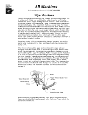
... the upper thread is held by the two pieces of magic tape contained in the direction of its travel the upper thread passes to better troubleshoot it and you a wiper out error. It hooks the upper thread after a trim you get a wiper out error and the thread is still in the...
... the upper thread is held by the two pieces of magic tape contained in the direction of its travel the upper thread passes to better troubleshoot it and you a wiper out error. It hooks the upper thread after a trim you get a wiper out error and the thread is still in the...

Service Manual
Page 6
... • 416A • BES-1210AC 121 8. Symbols 122 8-1-2. Machine motor circuit board connectors 118 7-17-3. Troubleshooting 122 ■ BAS-412A 122 8-1. Index PCB 104 7-13 TR breakage sensor PCB 105 7-14. DIP switch functions on main printed circuit board 113 7-16-3. Main circuit board ...
... • 416A • BES-1210AC 121 8. Symbols 122 8-1-2. Machine motor circuit board connectors 118 7-17-3. Troubleshooting 122 ■ BAS-412A 122 8-1. Index PCB 104 7-13 TR breakage sensor PCB 105 7-14. DIP switch functions on main printed circuit board 113 7-16-3. Main circuit board ...

Service Manual
Page 7
... Control block diagram 158 BES-1210AC Control block diagram 159 BAS-401 • 412A • 416A BES-1210AC Electrical problem 146 10. ■ BAS-401 • 416A • BES-1210AC 133 8-3. Finding cause of problen 144 9-1. Troubleshooting flow chart 134 ■ When power is turned ON: 134 ■ In data entry mode 135...
... Control block diagram 158 BES-1210AC Control block diagram 159 BAS-401 • 412A • 416A BES-1210AC Electrical problem 146 10. ■ BAS-401 • 416A • BES-1210AC 133 8-3. Finding cause of problen 144 9-1. Troubleshooting flow chart 134 ■ When power is turned ON: 134 ■ In data entry mode 135...

Service Manual
Page 129
8. Symbols 1. 2. 3. 4. 5. indicates that the procedure to follow appears on the next page. 7. indicates turning-off the power switch. Troubleshooting ■ BAS-412A 8-1. indicates switch operation. selects the course of "problem determination and solution table." indicates manual operation. indicates that the procedure to follow appears in the first column of action to follow , using a yes-or-no decision-making process. Trouble shooting flow chart 8-1-1. indicates setting-up operation. 6. BAS-401 • 412A 416A- BES-1210AC 122
8. Symbols 1. 2. 3. 4. 5. indicates that the procedure to follow appears on the next page. 7. indicates turning-off the power switch. Troubleshooting ■ BAS-412A 8-1. indicates switch operation. selects the course of "problem determination and solution table." indicates manual operation. indicates that the procedure to follow appears in the first column of action to follow , using a yes-or-no decision-making process. Trouble shooting flow chart 8-1-1. indicates setting-up operation. 6. BAS-401 • 412A 416A- BES-1210AC 122

Service Manual
Page 130
NO [ENTER] [EDIT) [COMMUNICATE] NO ISTART(sewIng)] #2 are displayed. YES \ Turn off power. / END 123 BAS-401 • 412A • 416A- 8-1-2. BES-1210AC Troubleshooting flow chart ■ When power is turned ON: ( START ) \ Turn on power. / "Keyboard ROM NG" YES #1 is displayed. NO "CAUTION MOVINGI" NO #2 is displayed. NO "Over ravel" YES #4 is disp ayed. YES "Missed X(Y) origin point" YES #3 is displayed.
NO [ENTER] [EDIT) [COMMUNICATE] NO ISTART(sewIng)] #2 are displayed. YES \ Turn off power. / END 123 BAS-401 • 412A • 416A- 8-1-2. BES-1210AC Troubleshooting flow chart ■ When power is turned ON: ( START ) \ Turn on power. / "Keyboard ROM NG" YES #1 is displayed. NO "CAUTION MOVINGI" NO #2 is displayed. NO "Over ravel" YES #4 is disp ayed. YES "Missed X(Y) origin point" YES #3 is displayed.

Service Manual
Page 139
... • Editing system defective • Main circuit board defective Check that RS cable is distorted. . b. a. Replace main circuit board. BAS-401 • 412A • 416A - Check if machine is operated in troubleshooting. #15 Embroidery is correctly connected and proper continuity tested for . Check that power is normal. ® With connector P1 unplugged...
... • Editing system defective • Main circuit board defective Check that RS cable is distorted. . b. a. Replace main circuit board. BAS-401 • 412A • 416A - Check if machine is operated in troubleshooting. #15 Embroidery is correctly connected and proper continuity tested for . Check that power is normal. ® With connector P1 unplugged...

Service Manual
Page 141
8-3-2. YES \ Turn off power. / END BAS-401 • 412A• 416A • BES-1210AC 134 YES "X_ (Y_) ORG. NO "File No.**" NO #2 is disp ayed. NO "CAUTION MOVINGI " NO #2 is disp ayed. Error" YES #3 is disp ayed. Troubleshooting flow chart • When power is turned ON: ( START ) \ Turn on power. / "Keyboard ROM NG" YES is disp ayed. NO "Over ravel" YES #4 is disp eyed.
8-3-2. YES \ Turn off power. / END BAS-401 • 412A• 416A • BES-1210AC 134 YES "X_ (Y_) ORG. NO "File No.**" NO #2 is disp ayed. NO "CAUTION MOVINGI " NO #2 is disp ayed. Error" YES #3 is disp ayed. Troubleshooting flow chart • When power is turned ON: ( START ) \ Turn on power. / "Keyboard ROM NG" YES is disp ayed. NO "Over ravel" YES #4 is disp eyed.
Service Manual
Page 150
... • Fuse F2 blown • Refer to item #10. 143 BAS-401 - 412A • 416A - If it is + 60V, it is correctly connected and proper continuity tested for . Main circuit board .. - Replace main circuit board. Check that RS cable is operated in troubleshooting. C) Check connector P1 is normal. (D With connector P1 unplugged...
... • Fuse F2 blown • Refer to item #10. 143 BAS-401 - 412A • 416A - If it is + 60V, it is correctly connected and proper continuity tested for . Main circuit board .. - Replace main circuit board. Check that RS cable is operated in troubleshooting. C) Check connector P1 is normal. (D With connector P1 unplugged...


