

Instruction Manual - English
Page 2
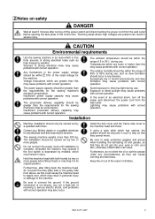
... safe operation of this machine and to prevent accidents and injury to carry out work while positioned directly in front of these parts. This symbol ( ) indicates something that you must make the ground connection".) i BAS-341F, 342F Symbols This symbol ( ) indicates something that can be careful of injury that you will almost certainly result in the instruction manual. Indications D A N G E R The instructions which...
... safe operation of this machine and to prevent accidents and injury to carry out work while positioned directly in front of these parts. This symbol ( ) indicates something that you must make the ground connection".) i BAS-341F, 342F Symbols This symbol ( ) indicates something that can be careful of injury that you will almost certainly result in the instruction manual. Indications D A N G E R The instructions which...
Instruction Manual - English
Page 3
..., and problems with correct operation. Exposure to direct sunlight may cause problems with correct operation. In the event of an electrical storm, turn off the power switch and disconnecting the power cord from the wall outlet before opening the face plate of the control box. Temperatures which are lower or higher than 200 kg. Avoid exposure to direct sunlight during use . Install the belt cover and...
..., and problems with correct operation. Exposure to direct sunlight may cause problems with correct operation. In the event of an electrical storm, turn off the power switch and disconnecting the power cord from the wall outlet before opening the face plate of the control box. Temperatures which are lower or higher than 200 kg. Avoid exposure to direct sunlight during use . Install the belt cover and...

Instruction Manual - English
Page 4
Set the needle to the needle up stop position before using a work table which could result in personal injury or damage to the machine will not be covered by the warranty. Do not touch any of any applications other than sewing. If the machine develops a problem, contact your nearest Brother dealer or a qualified technician. Keep the oil out of the reach of the broken needle may...
Set the needle to the needle up stop position before using a work table which could result in personal injury or damage to the machine will not be covered by the warranty. Do not touch any of any applications other than sewing. If the machine develops a problem, contact your nearest Brother dealer or a qualified technician. Keep the oil out of the reach of the broken needle may...

Instruction Manual - English
Page 6
...foot switch ...5 3-7. Adjusting the air pressure ...7 4. Lubrication points ...8 5. Installing the needle and urnning the sewing machine 9 5-3. Lower thread tension ...13 5-6-3. Thread take -up spring height ...13 5-6-5. USING THE OPERATION PANEL 15 6-1. Explanation of panel ...15 6-2. Using the program R/W (Read/Write) switch ...19 6-4. Shifting a stitch pattern ...26 BAS-341F, 342F PREPARATION ...3 3-1. LUBRICATION ...8 4-1. Threading the upper thread ...10 5-4. Using single split mode ...25 6-11. Installing the spool stand ...6 3-8. Winding the lower thread...
...foot switch ...5 3-7. Adjusting the air pressure ...7 4. Lubrication points ...8 5. Installing the needle and urnning the sewing machine 9 5-3. Lower thread tension ...13 5-6-3. Thread take -up spring height ...13 5-6-5. USING THE OPERATION PANEL 15 6-1. Explanation of panel ...15 6-2. Using the program R/W (Read/Write) switch ...19 6-4. Shifting a stitch pattern ...26 BAS-341F, 342F PREPARATION ...3 3-1. LUBRICATION ...8 4-1. Threading the upper thread ...10 5-4. Using single split mode ...25 6-11. Installing the spool stand ...6 3-8. Winding the lower thread...

Instruction Manual - English
Page 7
Sewing operation ...27 8. Cleaning the shuttle hook ...29 8-2. Cleaning the control box air inlet port ...30 8-5. Changing the presser foot lift ...37 9-9. Panel DIP switch functions ...41 10-2. SEWING ...27 7-1. Adjusting the shuttle race thread guide ...33 9-6. Adjusting the presser foot ...36 9-8. Clearing all memory settings ...40 10. NOTES ON THE PROCESSING AND PRODUCTION OF PLATE BLANKS...53 15. TROUBLESHOOTING ...54 16. MAINTENANCE AND INSPECTION 29 8-1. Draining the oil ...30 8-4. STANDARD ADJUSTMENTS ...32 9-1. Adjusting the needle clearance...
Sewing operation ...27 8. Cleaning the shuttle hook ...29 8-2. Cleaning the control box air inlet port ...30 8-5. Changing the presser foot lift ...37 9-9. Panel DIP switch functions ...41 10-2. SEWING ...27 7-1. Adjusting the shuttle race thread guide ...33 9-6. Adjusting the presser foot ...36 9-8. Clearing all memory settings ...40 10. NOTES ON THE PROCESSING AND PRODUCTION OF PLATE BLANKS...53 15. TROUBLESHOOTING ...54 16. MAINTENANCE AND INSPECTION 29 8-1. Draining the oil ...30 8-4. STANDARD ADJUSTMENTS ...32 9-1. Adjusting the needle clearance...

Instruction Manual - English
Page 9
... sewing machine (with large shuttle hook) Maximum pattern size BAS-341F: 250X 150 mm, BAS-342F: 300 X 200 mm Maximum stitch number 20,000 (one pattern) Stitch length 0.1 - 12.7 mm Maximum sewing speed 2,500 rpm (When stitch length is 3 mm or less) Feed mechanism Intermittent feed, pulse motor drive Shuttle hook Double hook (Standard hook is sold separately) Needle DP X 5, DP X 17, MR Data storage method 3.5 floppy disk 2HD/1.44MB, 2DD Test function Operation test function provided for use...
... sewing machine (with large shuttle hook) Maximum pattern size BAS-341F: 250X 150 mm, BAS-342F: 300 X 200 mm Maximum stitch number 20,000 (one pattern) Stitch length 0.1 - 12.7 mm Maximum sewing speed 2,500 rpm (When stitch length is 3 mm or less) Feed mechanism Intermittent feed, pulse motor drive Shuttle hook Double hook (Standard hook is sold separately) Needle DP X 5, DP X 17, MR Data storage method 3.5 floppy disk 2HD/1.44MB, 2DD Test function Operation test function provided for use...

Instruction Manual - English
Page 18
... its original position after the machine starts operating. Release the foot switch (3). 7. 5. CORRECT USE 5-4. Turn on the power switch. (The POWER indicator on as shown in A, turn the bobbin winder thread tension stud (2) to the machine may result. 1. if it once more thread onto the bobbin, loosen the set amount of thread (80 - 90% of the moving parts while winding the lower thread, otherwise personal injury or damage to adjust. To wind more...
... its original position after the machine starts operating. Release the foot switch (3). 7. 5. CORRECT USE 5-4. Turn on the power switch. (The POWER indicator on as shown in A, turn the bobbin winder thread tension stud (2) to the machine may result. 1. if it once more thread onto the bobbin, loosen the set amount of thread (80 - 90% of the moving parts while winding the lower thread, otherwise personal injury or damage to adjust. To wind more...

Instruction Manual - English
Page 19
... result in the above table may need to observe all safety precautions. Sewing conditions and thread tension 5-6-1. Replacing the bobbin case and threading the thread CAUTION If the power switch needs to be left on when carrying out replacing the bobbin, be extremely careful to be changed depending on the article being sewn. CORRECT USE 5-5. Sewing conditions Specifications Upper thread Lower thread Upper thread tension (N) Lower thread tension (N) Thread take-up spring height Thread take-up spring tension(N) Needle Normal sewing speed For heavy materials # 20...
... result in the above table may need to observe all safety precautions. Sewing conditions and thread tension 5-6-1. Replacing the bobbin case and threading the thread CAUTION If the power switch needs to be left on when carrying out replacing the bobbin, be extremely careful to be changed depending on the article being sewn. CORRECT USE 5-5. Sewing conditions Specifications Upper thread Lower thread Upper thread tension (N) Lower thread tension (N) Thread take-up spring height Thread take-up spring tension(N) Needle Normal sewing speed For heavy materials # 20...

Instruction Manual - English
Page 23
... Used when winding a fresh bobbin, or when correcting a stitch pattern due to continue sewing after replacing the bobbin thread. Using the bobbin thread counter".) (15) TEST switch Used to move the feed mechanism only in the bobbin thread counter to floppy disk. (14) Bobbin Thread CHANGE Used to a (RESET switch) broken needle thread. USING THE OPERATION PANEL (5) (13) (14) (10) (11) (6) (12) (16) (15) (17) 1208S (10) Bobbin Thread COUNTER............Illuminates when bobbin thread counter mode has been selected using...
... Used when winding a fresh bobbin, or when correcting a stitch pattern due to continue sewing after replacing the bobbin thread. Using the bobbin thread counter".) (15) TEST switch Used to move the feed mechanism only in the bobbin thread counter to floppy disk. (14) Bobbin Thread CHANGE Used to a (RESET switch) broken needle thread. USING THE OPERATION PANEL (5) (13) (14) (10) (11) (6) (12) (16) (15) (17) 1208S (10) Bobbin Thread COUNTER............Illuminates when bobbin thread counter mode has been selected using...

Instruction Manual - English
Page 30
... the counter (5). Using the bobbin thread counter Set the bobbin thread counter to . Press the bobbin thread change switch (14) and replace the bobbin. An alarm will decrease one each time the stitch pattern is sewn, the counter (5) will red , and an alarm will sound. (The sewing machine will record the number of bobbin thread remaining. 2. When the number of a patern. (5) (13) (14) (10) (6) (12) (17) 1222S 1. USING THE OPERATION PANEL 6-8. The...
... the counter (5). Using the bobbin thread counter Set the bobbin thread counter to . Press the bobbin thread change switch (14) and replace the bobbin. An alarm will decrease one each time the stitch pattern is sewn, the counter (5) will red , and an alarm will sound. (The sewing machine will record the number of bobbin thread remaining. 2. When the number of a patern. (5) (13) (14) (10) (6) (12) (17) 1222S 1. USING THE OPERATION PANEL 6-8. The...
Instruction Manual - English
Page 36
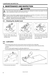
... remove the large shuttle hook (3) and the inner shuttle hook (4). 3. Fill the arm-side oil tank with oil. VG10) for a while after adding the oil. • Use only specified Brother oil (Nisseki Mitsubishi Sewing Lube 10N; BAS-341F,342F 29 1927S MAINTENANCE AND INSPECTION CAUTION Turn off the power switch before starting any circumstances, as they can result. Keep the oil out of the reach of the shuttle hook thread guide and the shuttle...
... remove the large shuttle hook (3) and the inner shuttle hook (4). 3. Fill the arm-side oil tank with oil. VG10) for a while after adding the oil. • Use only specified Brother oil (Nisseki Mitsubishi Sewing Lube 10N; BAS-341F,342F 29 1927S MAINTENANCE AND INSPECTION CAUTION Turn off the power switch before starting any circumstances, as they can result. Keep the oil out of the reach of the shuttle hook thread guide and the shuttle...
Instruction Manual - English
Page 39
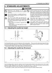
... the shuttle hook is aligned with the lower edge of the needle bar bush (1). * If using the machine. 9-1. STANDARD ADJUSTMENTS 9. Adjusting the needle bar height (1) a A 1237S 1949S Turn the machine pulley to move the needle bar up or down to the lowest position. Ask your Brother dealer or a qualified electrician to its original position. BAS-341F, 342F 32 9. Turn off the power switch and disconnect the power cord from the lowest position until...
... the shuttle hook is aligned with the lower edge of the needle bar bush (1). * If using the machine. 9-1. STANDARD ADJUSTMENTS 9. Adjusting the needle bar height (1) a A 1237S 1949S Turn the machine pulley to move the needle bar up or down to the lowest position. Ask your Brother dealer or a qualified electrician to its original position. BAS-341F, 342F 32 9. Turn off the power switch and disconnect the power cord from the lowest position until...

Instruction Manual - English
Page 43
...; After turning the pulley by hand to lower the presser foot to the normal operating position. 1931S BAS-341F, 342F 36 Loosen screw (1), set the bottom of needle sub panel (12). * One month is too high, skipped stitches may result. ■ To turn it by the connecting rod (7). 5. Fit the thread cutter connecting rod (7) on connecting lever pin (8), and install needle plate (6).(Figure is pulled by hand. Turn...
...; After turning the pulley by hand to lower the presser foot to the normal operating position. 1931S BAS-341F, 342F 36 Loosen screw (1), set the bottom of needle sub panel (12). * One month is too high, skipped stitches may result. ■ To turn it by the connecting rod (7). 5. Fit the thread cutter connecting rod (7) on connecting lever pin (8), and install needle plate (6).(Figure is pulled by hand. Turn...

Instruction Manual - English
Page 54
... air pressure drop detection switch. (This detection switch is available by special order.) Changes the split number automatically by special order.) When using outside switch. (Use optional connector P3 on the operation panel.) BAS-341F, 342F 47 Order is changed automatically by special order.) Starting switch causes work clamp to sew. DIP switch A-7 is decremented at the start of sewing. Produces two work clamp signal outputs (right and left work clamp lowers when starting...
... air pressure drop detection switch. (This detection switch is available by special order.) Changes the split number automatically by special order.) When using outside switch. (Use optional connector P3 on the operation panel.) BAS-341F, 342F 47 Order is changed automatically by special order.) Starting switch causes work clamp to sew. DIP switch A-7 is decremented at the start of sewing. Produces two work clamp signal outputs (right and left work clamp lowers when starting...

Instruction Manual - English
Page 56
... feed timing. 1 (Fast) 5 (standard) 10 (Slow) 1 Number of low-speed stitches sewn at 400 rpm at the time of shipment from inserting the cassette until feed mechanism starts moving after work clamp 3 : Lower-left corner of sewing pattern 10 : Upper-right corner of sewing pattern 11 : Lower-right corner of work clamp has lifted. Changes the reference point for enlargement and reduction using the operation panel. 0 : Sensor home position 1 : Center of work clamp 2 : Upper-left corner of sewing pattern Changes...
... feed timing. 1 (Fast) 5 (standard) 10 (Slow) 1 Number of low-speed stitches sewn at 400 rpm at the time of shipment from inserting the cassette until feed mechanism starts moving after work clamp 3 : Lower-left corner of sewing pattern 10 : Upper-right corner of sewing pattern 11 : Lower-right corner of work clamp has lifted. Changes the reference point for enlargement and reduction using the operation panel. 0 : Sensor home position 1 : Center of work clamp 2 : Upper-left corner of sewing pattern Changes...
Instruction Manual - English
Page 57
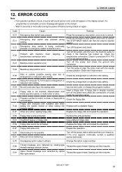
... Replace the floppy disk and repeat the operation. Input an end code, or change the program number. If floppy disk is not inserted, disconnected cord inside the operation panel. Remove the write-protection. Change the option output number. Sewing can then resume. Insert a floppy disk. Turn off the power and check. stop switch was pressed during Press the emergency stop position error. Thread the upper thread. memory switch. Thread the upper thread. BAS-341F...
... Replace the floppy disk and repeat the operation. Input an end code, or change the program number. If floppy disk is not inserted, disconnected cord inside the operation panel. Remove the write-protection. Change the option output number. Sewing can then resume. Insert a floppy disk. Turn off the power and check. stop switch was pressed during Press the emergency stop position error. Thread the upper thread. memory switch. Thread the upper thread. BAS-341F...
Instruction Manual - English
Page 61
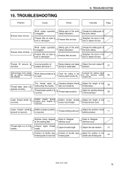
... stitches occur". Bobbin presser position is too light. Straighten the bend in the tube or replace the tube. Uneven upper thread length. Work clamp pressure is incorrect. Upper thread length Adjust the sub-tension. 13 Position of shuttle race thread guide is Incorrect position of the shuttle race thread guide 33 BAS-341F, 342F 54 Presser lift amount is incorrect Position of shuttle race thread guide Adjust the position of incorrect. Work clamp operation is incorrect. Bobbin winder thread tension stud heights is sluggish. TROUBLESHOOTING Problem Cause...
... stitches occur". Bobbin presser position is too light. Straighten the bend in the tube or replace the tube. Uneven upper thread length. Work clamp pressure is incorrect. Upper thread length Adjust the sub-tension. 13 Position of shuttle race thread guide is Incorrect position of the shuttle race thread guide 33 BAS-341F, 342F 54 Presser lift amount is incorrect Position of shuttle race thread guide Adjust the position of incorrect. Work clamp operation is incorrect. Bobbin winder thread tension stud heights is sluggish. TROUBLESHOOTING Problem Cause...
Instruction Manual - English
Page 62
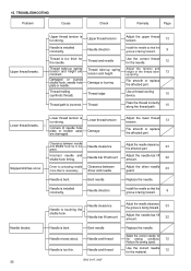
... the sewing speed Use the correct needle for the needle. 12 Thread take -up spring tension and height are damaged. Bent needle Needle moves about. the groove is incorrect. TROUBLESHOOTING Problem Cause Check Remedy Page Upper thread breaks. Upper thread tension is necessary. Incorrect needle and shuttle hook timing. Driver is contacting needle more than is too strong. Upper thread tension Adjust the upper thread tension. 13 Needle is installed incorrectly. Thread take -up spring tension and height Adjust the tension and height of needle hole plate or bobbin case...
... the sewing speed Use the correct needle for the needle. 12 Thread take -up spring tension and height are damaged. Bent needle Needle moves about. the groove is incorrect. TROUBLESHOOTING Problem Cause Check Remedy Page Upper thread breaks. Upper thread tension is necessary. Incorrect needle and shuttle hook timing. Driver is contacting needle more than is too strong. Upper thread tension Adjust the upper thread tension. 13 Needle is installed incorrectly. Thread take -up spring tension and height Adjust the tension and height of needle hole plate or bobbin case...

Instruction Manual - English
Page 63
... BAS-341F, 342F 56 Upper thread is not separating the threads. Shuttle race thread guide position Adjust the position of the shuttle race thread guide. 33 Poor seam finish on reverse side of the shuttle race thread guide. 33 Adjust the upper thread tension. 13 Adjust the sub-tension. 13 Incorrect thread tightness. Skipped stitches at the sewing end. Shuttle race thread guide is not properly tight. Thread take -up spring tension and height Adjust the tension and height of the thread takeup spring. 13 Incorrect needle and shuttle hook timing. Fixed knife...
... BAS-341F, 342F 56 Upper thread is not separating the threads. Shuttle race thread guide position Adjust the position of the shuttle race thread guide. 33 Poor seam finish on reverse side of the shuttle race thread guide. 33 Adjust the upper thread tension. 13 Adjust the sub-tension. 13 Incorrect thread tightness. Skipped stitches at the sewing end. Shuttle race thread guide is not properly tight. Thread take -up spring tension and height Adjust the tension and height of the thread takeup spring. 13 Incorrect needle and shuttle hook timing. Fixed knife...

Parts Manual - English
Page 4
... P. Air pressure mechanism 73 T. This book was prepared based on information available in design without prior notice. 3. Feed mechanism (BAS-341F) 17 C8. Thread breakage detector mechanism 47 F. Lower shaft mechanism 49 G. Power table 83 X. Accessories 101 Ga. Synchronizer 67 Q. Operation panel mechanism 79 V. Thread trimmer mechanism 59 L. Programmer (Option parts) 63 N. Control box mechanism 69 S. Thread wiper mechanism 63 M. Notes for using this parts book 1. Upper shaft and needle bar mechanism...
... P. Air pressure mechanism 73 T. This book was prepared based on information available in design without prior notice. 3. Feed mechanism (BAS-341F) 17 C8. Thread breakage detector mechanism 47 F. Lower shaft mechanism 49 G. Power table 83 X. Accessories 101 Ga. Synchronizer 67 Q. Operation panel mechanism 79 V. Thread trimmer mechanism 59 L. Programmer (Option parts) 63 N. Control box mechanism 69 S. Thread wiper mechanism 63 M. Notes for using this parts book 1. Upper shaft and needle bar mechanism...


