
Parts Manual - English
Page 30
...,2-4.37 WASHER, SPRING 2-4.37 225 148847001 4 ti-t4 , WASHER, PLAIN 4.76 226 226-1 S59741000 S59637001 1 '1=7h'41-'311'ell• 4 +1)-74X8 LENEAR GUIDE SET, 311 SCREW, FLAT M4X8 BAS-311F-0-202 24 Hvii-49 X-SENSOR SETTING PLATE 128 062400812 2 1-,\'N.X8 SCREW, PAN M4X8 129 025040232 2 L51)- )f4,T.ar)4 WASHER, PLAIN M 4 130 S42775101 1 XY21-999'-ft/C--L X-Y FEED BRACKET COVER, L 132 106629002...
...,2-4.37 WASHER, SPRING 2-4.37 225 148847001 4 ti-t4 , WASHER, PLAIN 4.76 226 226-1 S59741000 S59637001 1 '1=7h'41-'311'ell• 4 +1)-74X8 LENEAR GUIDE SET, 311 SCREW, FLAT M4X8 BAS-311F-0-202 24 Hvii-49 X-SENSOR SETTING PLATE 128 062400812 2 1-,\'N.X8 SCREW, PAN M4X8 129 025040232 2 L51)- )f4,T.ar)4 WASHER, PLAIN M 4 130 S42775101 1 XY21-999'-ft/C--L X-Y FEED BRACKET COVER, L 132 106629002...

Parts Manual - English
Page 44
C10.1g r41% (311F-L) / Feed mechanism (311F-L) REF.NO CODE Q'TY ri:Till i NAME OF PARTS RM 13 S59637001 8 +1)---)4X8 SCREW, FLAT M4X8 57 S44757101 1 7V11491t#IM SUPPORT PLATE GUIDE, M 58 060680712 2 K'fiV437- 40X7 SCREW, BIND SM4.37-40X7 65 S10091201 4 AIH971i'/V91)-1)-i AUXILIARY PLATE SUPPORT 67 S55935001 1 iF/VMIRD SUPPORT PLATE GUIDE, R :D 68 S55936001 1 ifiVV91J--itILD SUPPORT PLATE GUIDE, L :D 69 062761012 4 -)-- 595-28X10 SCREW, PAN SM5.95...
C10.1g r41% (311F-L) / Feed mechanism (311F-L) REF.NO CODE Q'TY ri:Till i NAME OF PARTS RM 13 S59637001 8 +1)---)4X8 SCREW, FLAT M4X8 57 S44757101 1 7V11491t#IM SUPPORT PLATE GUIDE, M 58 060680712 2 K'fiV437- 40X7 SCREW, BIND SM4.37-40X7 65 S10091201 4 AIH971i'/V91)-1)-i AUXILIARY PLATE SUPPORT 67 S55935001 1 iF/VMIRD SUPPORT PLATE GUIDE, R :D 68 S55936001 1 ifiVV91J--itILD SUPPORT PLATE GUIDE, L :D 69 062761012 4 -)-- 595-28X10 SCREW, PAN SM5.95...
Parts Manual - English
Page 52
... M4X8 BAS-326F-0-202 46 T-BELT SPACER 122 S47115001 1 Y,\ A440 Y-BELT HOLDER 123 S59890001 2 7t*'1[4-437-40X8 BOLT, SOCKET SM4.37-40X8 125 S42795101 1 Xir'.4->F9 HOME POSITION DOG, X 126 S44924001 2 'i)(V1M3X5.5 SCREW, M3X5.5 127 S42796001 1 xt>1)--i•M- (h X-SENSOR SETTING PLATE 128 062400812 2 -1-K4X8 SCREW, PAN M4X8 129 025040232 2 t54)-'t' ar,4 WASHER, PLAIN M 4 130 S51040001 1 XYth'W-ftiVs-L XY-FEED BRACKET COVER...
... M4X8 BAS-326F-0-202 46 T-BELT SPACER 122 S47115001 1 Y,\ A440 Y-BELT HOLDER 123 S59890001 2 7t*'1[4-437-40X8 BOLT, SOCKET SM4.37-40X8 125 S42795101 1 Xir'.4->F9 HOME POSITION DOG, X 126 S44924001 2 'i)(V1M3X5.5 SCREW, M3X5.5 127 S42796001 1 xt>1)--i•M- (h X-SENSOR SETTING PLATE 128 062400812 2 -1-K4X8 SCREW, PAN M4X8 129 025040232 2 t54)-'t' ar,4 WASHER, PLAIN M 4 130 S51040001 1 XYth'W-ftiVs-L XY-FEED BRACKET COVER...

Parts Manual - English
Page 128
... work clamp" WORK CLAMP BLANK, A-3.2 WORK CLAMP BLANK, B-3.2 WORK CLAMP BLANK, A-4.0 WORK CLAMP BLANK, B-4.0 WORK CLAMP BLANK, A-5.0 WORK CLAMP BLANK, B-5.0 WORK CLAMP BLANK, 6.0 205 S43986201 1 tliaTiUN 206 S43987001 1 3112fifiUN WORK CLAMP, UN :SOL WORK CLAMP, 311 UN BAS-311F-0-Ga3 *XFF10)1i5Aft, tiMURc'to *The X symbol is for Standard parts. 122 f li- l- Ga3.1f - .)iaRiPp -IW. (311F A- 9 :445A) / Gauge parts list (Option parts of 311F) REF.NO CODE Q'TY A NAME OF PARTS RM 138 S42888001 1 5- :/ -:/*V3->49/.-* H-POSITION...
... work clamp" WORK CLAMP BLANK, A-3.2 WORK CLAMP BLANK, B-3.2 WORK CLAMP BLANK, A-4.0 WORK CLAMP BLANK, B-4.0 WORK CLAMP BLANK, A-5.0 WORK CLAMP BLANK, B-5.0 WORK CLAMP BLANK, 6.0 205 S43986201 1 tliaTiUN 206 S43987001 1 3112fifiUN WORK CLAMP, UN :SOL WORK CLAMP, 311 UN BAS-311F-0-Ga3 *XFF10)1i5Aft, tiMURc'to *The X symbol is for Standard parts. 122 f li- l- Ga3.1f - .)iaRiPp -IW. (311F A- 9 :445A) / Gauge parts list (Option parts of 311F) REF.NO CODE Q'TY A NAME OF PARTS RM 138 S42888001 1 5- :/ -:/*V3->49/.-* H-POSITION...

Instruction Manual - English
Page 4
.... When carrying out inspection, adjustment and maintenance When replacing consumable parts such as the rotary hook Disconnect the air hoses from above, as this is not done, the wiper may operate if the foot switch is the danger that if a needle breaks, parts of children. Any problems in safe use the pneumatic equipment. If the machine develops a problem, contact your nearest Brother dealer or a qualified...
.... When carrying out inspection, adjustment and maintenance When replacing consumable parts such as the rotary hook Disconnect the air hoses from above, as this is not done, the wiper may operate if the foot switch is the danger that if a needle breaks, parts of children. Any problems in safe use the pneumatic equipment. If the machine develops a problem, contact your nearest Brother dealer or a qualified...

Instruction Manual - English
Page 6
...Installing the spool stand ...14 3-15. LUBRICATION...20 5. Adjusting arm thread guide R...25 6. Adjusting the speed controller ...19 4. CORRECT OPERATION ...21 5-1. Installing the needle ...21 5-3. Threading the upper thread ...22 5-4. NAME OF MAJOR PARTS ...1 2. Positioning ...4 3-3. Installing the oil pan ...6 3-6. Installing the machine head ...8 3-9. Installing the work clamp lifter connecting rod (BAS-311F-0 solenoid type only 16 3-18. Installing the air unit...19 3-20-2. Sewing conditions and thread tension ...24 5-6-1. Thread take -up spring tension ...25 5-6-6. Using...
...Installing the spool stand ...14 3-15. LUBRICATION...20 5. Adjusting arm thread guide R...25 6. Adjusting the speed controller ...19 4. CORRECT OPERATION ...21 5-1. Installing the needle ...21 5-3. Threading the upper thread ...22 5-4. NAME OF MAJOR PARTS ...1 2. Positioning ...4 3-3. Installing the oil pan ...6 3-6. Installing the machine head ...8 3-9. Installing the work clamp lifter connecting rod (BAS-311F-0 solenoid type only 16 3-18. Installing the air unit...19 3-20-2. Sewing conditions and thread tension ...24 5-6-1. Thread take -up spring tension ...25 5-6-6. Using...

Instruction Manual - English
Page 7
... control box ...56 11. 6-8. GAUGE PARTS LIST ACCORDING TO SUBCLASSES 66 14. Using the bobbin thread counter ...34 6-9. Draining the oil ...40 8-4. Adjusting the needle bar height ...42 9-2. Adjusting the needle bar lift amount ...42 9-3. Adjusting the driver needle guard ...43 9-5. Changing the presser foot lift ...47 9-9. BAS-311F-0, 311F-L Pneumatic type ...49 9-10-3. Sewing operation ...38 8. Checking the input sensor and DIP switch input 52 9-13. Adjusting the shuttle race thread guide ...43 9-6. Clearing all memory settings...
... control box ...56 11. 6-8. GAUGE PARTS LIST ACCORDING TO SUBCLASSES 66 14. Using the bobbin thread counter ...34 6-9. Draining the oil ...40 8-4. Adjusting the needle bar height ...42 9-2. Adjusting the needle bar lift amount ...42 9-3. Adjusting the driver needle guard ...43 9-5. Changing the presser foot lift ...47 9-9. BAS-311F-0, 311F-L Pneumatic type ...49 9-10-3. Sewing operation ...38 8. Checking the input sensor and DIP switch input 52 9-13. Adjusting the shuttle race thread guide ...43 9-6. Clearing all memory settings...

Instruction Manual - English
Page 9
... for use with intermediate stop function and safety circuits Work clamp height BAS-311F-0:For solenoid - unit work clamp, for pneumatic - SPECIFICATIONS 2. Max. 17 mm, for pneumatic - separate work clamp BAS-311F-L, BAS-326F-0:Separate work clamp BAS-311F-0:For solenoid - 2. SPECIFICATIONS Stitch formation Sewing machine Maximum pattern size Maximum stitch number Stitch length Maximum sewing speed Feed mechanism Single needle lock stitch Lock stitch, pattern tacking sewing machine (with large shuttle hook) BAS-311F-0: 130 X 60 mm, BAS-311F-L: 220 X 60 mm, BAS-326F-0: 220...
... for use with intermediate stop function and safety circuits Work clamp height BAS-311F-0:For solenoid - unit work clamp, for pneumatic - SPECIFICATIONS 2. Max. 17 mm, for pneumatic - separate work clamp BAS-311F-L, BAS-326F-0:Separate work clamp BAS-311F-0:For solenoid - 2. SPECIFICATIONS Stitch formation Sewing machine Maximum pattern size Maximum stitch number Stitch length Maximum sewing speed Feed mechanism Single needle lock stitch Lock stitch, pattern tacking sewing machine (with large shuttle hook) BAS-311F-0: 130 X 60 mm, BAS-311F-L: 220 X 60 mm, BAS-326F-0: 220...
Instruction Manual - English
Page 19
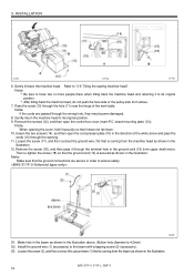
... 4.2mm) S2. Then re-tighten the screw (18) so that is coming from upper shaft motor. Gently return the machine head to its original position. 9. Remove the screws (12), and then open the cord presser plate (15) in the illustration. Tilting the sewing machine head". loosen the two screws (14), and then open the control box cover (main P.C. Note Make sure that it to its original position. BAS-311F-0, 311F-L, 326F-0 12
... 4.2mm) S2. Then re-tighten the screw (18) so that is coming from upper shaft motor. Gently return the machine head to its original position. 9. Remove the screws (12), and then open the cord presser plate (15) in the illustration. Tilting the sewing machine head". loosen the two screws (14), and then open the control box cover (main P.C. Note Make sure that it to its original position. BAS-311F-0, 311F-L, 326F-0 12

Instruction Manual - English
Page 26
... (6). 5. Adjust the air pressure. (Refer to set the appropriate speed. Adjusting the air pressure".) 1. Adjust the knob position to "9-10-4. If the lower knob is screwed inward, the work clamp ......Pitch 120 mm 2. Install the air unit (5) to the valve setting plate (2) with two accessory screws (8) and two bolts (9). 3. Make holes in the beam as accessories. 3. Adjusting the speed controller The raising and lowering speeds for the work clamp operate at the same speed. The work clamp can then be adjusted so...
... (6). 5. Adjust the air pressure. (Refer to set the appropriate speed. Adjusting the air pressure".) 1. Adjust the knob position to "9-10-4. If the lower knob is screwed inward, the work clamp ......Pitch 120 mm 2. Install the air unit (5) to the valve setting plate (2) with two accessory screws (8) and two bolts (9). 3. Make holes in the beam as accessories. 3. Adjusting the speed controller The raising and lowering speeds for the work clamp operate at the same speed. The work clamp can then be adjusted so...

Instruction Manual - English
Page 30
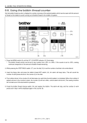
... POWER indicator on . 6. Thread the thread as shown in A, turn the bobbin winder thread tension stud (2) to start the machine. BAS-311F-0, 311F-L, 326F-0 23 Release the foot switch (3). 7. The bobbin presser (1) will illuminate.) For solenoid specifications, lower the work clamp (depress the work clamp lifter pedal (6)). 1198S 1429S (2) (6) (3) (5) (4) (1) 0107Q A B 0108Q 4. Winding the lower thread CAUTION Do not touch or place anything against any of the bobbin capacity) has been wound on the operation panel will automatically...
... POWER indicator on . 6. Thread the thread as shown in A, turn the bobbin winder thread tension stud (2) to start the machine. BAS-311F-0, 311F-L, 326F-0 23 Release the foot switch (3). 7. The bobbin presser (1) will illuminate.) For solenoid specifications, lower the work clamp (depress the work clamp lifter pedal (6)). 1198S 1429S (2) (6) (3) (5) (4) (1) 0107Q A B 0108Q 4. Winding the lower thread CAUTION Do not touch or place anything against any of the bobbin capacity) has been wound on the operation panel will automatically...

Instruction Manual - English
Page 34
... needle thread. mode has been selected using the menu indicator switch (6). (11) SPLIT NO. indicator Illuminates when split No. Sewing is pressed. (17) STEP BACK switch Used when winding a fresh bobbin, or when correcting a stitch pattern due to "6-8. Using the bobbin thread counter".) (15) TEST switch Used to move the feed mechanism only in the bobbin thread counter to floppy disk. (14) Bobbin Thread CHANGE Used to reset error displays. BAS-311F-0, 311F-L, 326F...
... needle thread. mode has been selected using the menu indicator switch (6). (11) SPLIT NO. indicator Illuminates when split No. Sewing is pressed. (17) STEP BACK switch Used when winding a fresh bobbin, or when correcting a stitch pattern due to "6-8. Using the bobbin thread counter".) (15) TEST switch Used to move the feed mechanism only in the bobbin thread counter to floppy disk. (14) Bobbin Thread CHANGE Used to reset error displays. BAS-311F-0, 311F-L, 326F...
Instruction Manual - English
Page 41
... the bobbin thread change switch (14) and replace the bobbin. If the counter is pressed.) 5. BAS-311F-0, 311F-L, 326F-0 34 Press the MENU switch (6) until the B.T. USING THE OPERATION PANEL 6-8. The bobbin thread counter can be displayed again in the middle of the selected pattern which can be embroidered. 3. This will decrease one each time the stitch pattern is completed. The number shown in the counter (5) to , sewing...
... the bobbin thread change switch (14) and replace the bobbin. If the counter is pressed.) 5. BAS-311F-0, 311F-L, 326F-0 34 Press the MENU switch (6) until the B.T. USING THE OPERATION PANEL 6-8. The bobbin thread counter can be displayed again in the middle of the selected pattern which can be embroidered. 3. This will decrease one each time the stitch pattern is completed. The number shown in the counter (5) to , sewing...
Instruction Manual - English
Page 69
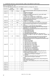
... (Slow) 1 Number of time from inserting the cassette until feed mechanism starts moving after work clamp capacity) 1 The solenoid ON time when the presser foot is used, reduce the setting to change the values. Solenoid ON time changes (BAS-311F solenoid specifications 40 only). 10 (Quiet) 60 (High work clamp has lifted. Changes the reference point for enlargement and reduction using the operation panel. 0 : Sensor home position 1 : Center of work clamp 2 : Upper-left corner of work clamp 6 : Sewing start . Switch...
... (Slow) 1 Number of time from inserting the cassette until feed mechanism starts moving after work clamp capacity) 1 The solenoid ON time when the presser foot is used, reduce the setting to change the values. Solenoid ON time changes (BAS-311F solenoid specifications 40 only). 10 (Quiet) 60 (High work clamp has lifted. Changes the reference point for enlargement and reduction using the operation panel. 0 : Sensor home position 1 : Center of work clamp 2 : Upper-left corner of work clamp 6 : Sewing start . Switch...

Instruction Manual - English
Page 70
... opening the face plate of foot Turn off power and check it . Motor malfunctioned. Data exceeds available sewing area due to release it . Press the STEP BACK (RESET) switch on the display screen; switch is activated or its Turn off power and check it . Operation panel switch was depressed, or connection of model selection connector. Needle up stop switch is defective. Stitch length...
... opening the face plate of foot Turn off power and check it . Motor malfunctioned. Data exceeds available sewing area due to release it . Press the STEP BACK (RESET) switch on the display screen; switch is activated or its Turn off power and check it . Operation panel switch was depressed, or connection of model selection connector. Needle up stop switch is defective. Stitch length...

Instruction Manual - English
Page 71
... not inserted or operation panel cable Insert a floppy disk. E.63 Combination of the memory setting. E.75 Milling motor has stopped due to OFF. BAS-311F-0, 311F-L, 326F-0 64 E.41 Invalid program No., or no data. E.70 Same optional output number already exists. E.74 See the manual for Milling motor. E.80 Upper thread has broken. (Rotary type sensor) See the manual for bobbin changer. E.81 Upper thread has...
... not inserted or operation panel cable Insert a floppy disk. E.63 Combination of the memory setting. E.75 Milling motor has stopped due to OFF. BAS-311F-0, 311F-L, 326F-0 64 E.41 Invalid program No., or no data. E.70 Same optional output number already exists. E.74 See the manual for Milling motor. E.80 Upper thread has broken. (Rotary type sensor) See the manual for bobbin changer. E.81 Upper thread has...

Instruction Manual - English
Page 75
... replace the tube. 18 Presser lift amount is too light. clamp lubrication the work clamp. Bobbin winder thread tension stud height Adjust the height of the shuttle race thread guide 43 *.........For Air type 68 BAS-311F-0, 311F-L, 326F-0 Refer to "Skipped at the sewing start. Work clamp operation Sliding part of the work Grease the sliding part of the needle. presser arm lever F. Increase the setting value of is sluggish. Thread wiper position is Hook the link return moving back. Bobbin presser position is incorrect. Thread...
... replace the tube. 18 Presser lift amount is too light. clamp lubrication the work clamp. Bobbin winder thread tension stud height Adjust the height of the shuttle race thread guide 43 *.........For Air type 68 BAS-311F-0, 311F-L, 326F-0 Refer to "Skipped at the sewing start. Work clamp operation Sliding part of the work Grease the sliding part of the needle. presser arm lever F. Increase the setting value of is sluggish. Thread wiper position is Hook the link return moving back. Bobbin presser position is incorrect. Thread...
Instruction Manual - English
Page 76
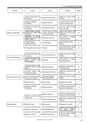
.... Bent needle Needle moves about. Problem Cause Check 14. Needle direction Adjust the lower thread tension. 25 File smooth or replace the affected part. Needle and thread BAS-311F-0, 311F-L, 326F-0 Adjust the needle clearance. Select the correct needle for the sewing conditions. 21 Reduce the sewing speed Use the correct needle for the needle. Needle is facing forward. 21 Needle breaks. Damage or burring File smooth or replace the affected part. Adjust the needle clearance. Incorrect needle and rotary hook timing. Install the needle so...
.... Bent needle Needle moves about. Problem Cause Check 14. Needle direction Adjust the lower thread tension. 25 File smooth or replace the affected part. Needle and thread BAS-311F-0, 311F-L, 326F-0 Adjust the needle clearance. Select the correct needle for the sewing conditions. 21 Reduce the sewing speed Use the correct needle for the needle. Needle is facing forward. 21 Needle breaks. Damage or burring File smooth or replace the affected part. Adjust the needle clearance. Incorrect needle and rotary hook timing. Install the needle so...

Instruction Manual - English
Page 77
.... Sub-tension Sharpen or replace the fixed knife. Shuttle race thread guide position Adjust the position of the shuttle race thread guide. 43 Poor seam finish on reverse side of the shuttle race thread guide. 43 Adjust the upper thread tension. 25 Adjust the sub-tension. 25 Incorrect thread tightness. Shuttle race thread guide position Upper thread tension Upper thread length Adjust the position of material. Upper thread tension is not separating the threads. Thread take up spring tension and height are incorrect. Shuttle race thread guide position Needle bar lift amount...
.... Sub-tension Sharpen or replace the fixed knife. Shuttle race thread guide position Adjust the position of the shuttle race thread guide. 43 Poor seam finish on reverse side of the shuttle race thread guide. 43 Adjust the upper thread tension. 25 Adjust the sub-tension. 25 Incorrect thread tightness. Shuttle race thread guide position Upper thread tension Upper thread length Adjust the position of material. Upper thread tension is not separating the threads. Thread take up spring tension and height are incorrect. Shuttle race thread guide position Needle bar lift amount...

Hand Book - English
Page 1
... Model BAS-311F-0□□ 1 For heavy-weight materials 2 For medium-weight materials 3 For extra heavy-weight materials 4 For special use S Work clamp lifter (Solenoid type) A Work clamp lifter (Pneumatic type) Specifications Stitch formation Sewing machine Maximum pattern size Maximum stitch number Stitch length Maximum sewing speed Feed mechanism Rotary hook Needle Data storage method Test function Safety devices Work clamp height 2-step work clamp Work clamp lift stroke Intermittent stroke Weights Power supply Motor Air pressure Power table Machine dimensions Single needle lock...
... Model BAS-311F-0□□ 1 For heavy-weight materials 2 For medium-weight materials 3 For extra heavy-weight materials 4 For special use S Work clamp lifter (Solenoid type) A Work clamp lifter (Pneumatic type) Specifications Stitch formation Sewing machine Maximum pattern size Maximum stitch number Stitch length Maximum sewing speed Feed mechanism Rotary hook Needle Data storage method Test function Safety devices Work clamp height 2-step work clamp Work clamp lift stroke Intermittent stroke Weights Power supply Motor Air pressure Power table Machine dimensions Single needle lock...


