

User Manual in English
Page 1
... your choice for marine audio entertainment! USER'S MANUAL page CONTENTS 2 Introduction 2 What is included? 3 Features 3 About 2 Ohm operation 4 General precautions 4 Protection circuitry 5 Installation precautions 5 Fuses 6 Mounting the amplifier 6 Connecting the amplifier 8 Low level input wiring 10 High level input wiring 13 Power and speaker wiring 18 Troubleshooting 19 Specifications Marine MOSFET Amplifier User's Manual - page 1 It has been...
... your choice for marine audio entertainment! USER'S MANUAL page CONTENTS 2 Introduction 2 What is included? 3 Features 3 About 2 Ohm operation 4 General precautions 4 Protection circuitry 5 Installation precautions 5 Fuses 6 Mounting the amplifier 6 Connecting the amplifier 8 Low level input wiring 10 High level input wiring 13 Power and speaker wiring 18 Troubleshooting 19 Specifications Marine MOSFET Amplifier User's Manual - page 1 It has been...
User Manual in English
Page 2
... Marine MOSFET Amplifier User's Manual - In order to prevent the intrusion of water into your system regardless of the nature of your new amplifier, please check first that the package contains all control openings. 304, Marine understands that amplifiers are introducing two new amplifiers, designed specifically for marine audio installations. All 39b5 Marine models feature both...
... Marine MOSFET Amplifier User's Manual - In order to prevent the intrusion of water into your system regardless of the nature of your new amplifier, please check first that the package contains all control openings. 304, Marine understands that amplifiers are introducing two new amplifiers, designed specifically for marine audio installations. All 39b5 Marine models feature both...
User Manual in English
Page 3
... woofers per channel at low frequencies (below 100Hz) produces an acoustic coupling effect. When operating at loads down to 2 Ohms. This means that you can install four 8 Ohm speakers per speaker. The current draw will be sure you have enough current to run the amplifiers into a 2 Ohm load. If you lack... power by about the same amount, so be distorted. Increasing the number of an additional 10W per channel, when using parallel wiring. Marine MOSFET Amplifier User's Manual -
... woofers per channel at low frequencies (below 100Hz) produces an acoustic coupling effect. When operating at loads down to 2 Ohms. This means that you can install four 8 Ohm speakers per speaker. The current draw will be sure you have enough current to run the amplifiers into a 2 Ohm load. If you lack... power by about the same amount, so be distorted. Increasing the number of an additional 10W per channel, when using parallel wiring. Marine MOSFET Amplifier User's Manual -
User Manual in English
Page 4
...short circuit, be illuminated. If the shut down was due to repair this product. General precautions Before installing andusingyournew 19b5 Marine amplifier, please become damp or wet from water ...the model number badge on , please check the system carefully to determine what has caused the protection circuit to power up the amplifier again. SHOCK HAZARD! There are no user-serviceable parts ...service center as soon as possible. • If there is smoke or any peculiar odor present during use or if there is in electric shock. If this manual. Marine MOSFET Amplifier User's Manual...
...short circuit, be illuminated. If the shut down was due to repair this product. General precautions Before installing andusingyournew 19b5 Marine amplifier, please become damp or wet from water ...the model number badge on , please check the system carefully to determine what has caused the protection circuit to power up the amplifier again. SHOCK HAZARD! There are no user-serviceable parts ...service center as soon as possible. • If there is smoke or any peculiar odor present during use or if there is in electric shock. If this manual. Marine MOSFET Amplifier User's Manual...
User Manual in English
Page 5
...in contact with any holes, investigate your marine vessel, or likely to be damaged by the manufacturer's warranty. Marine MOSFET Amplifier User's Manual - Installation precautions Before you drill or cut any metal surfaces in an accident. Confirm that supplied with a fuse identical to prevent damage,... especially in your vessel's layout very carefully. If you need to replace the power fuse, replace it is not covered by nearby objects. Attach all audio system components securely within the amplifier to that your boat from fault conditions. Fuses ...
...in contact with any holes, investigate your marine vessel, or likely to be damaged by the manufacturer's warranty. Marine MOSFET Amplifier User's Manual - Installation precautions Before you drill or cut any metal surfaces in an accident. Confirm that supplied with a fuse identical to prevent damage,... especially in your vessel's layout very carefully. If you need to replace the power fuse, replace it is not covered by nearby objects. Attach all audio system components securely within the amplifier to that your boat from fault conditions. Fuses ...
User Manual in English
Page 6
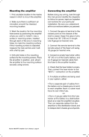
...before you wish to the remote output of the head unit using screws. Connect the remote terminal to install it. If multiple amplifiers are being used in the mounting surface for the mounting hole screws by ...point to the "BATT+" connection on the chassis of the boat's battery, and run separate cables from this manual and identify the diagrams to follow for power, input and speaker connections for your system, either: • Run... with a felt tip pen. 4. Drill pilot holes in your particular installation. Check that the fuse holder is empty. Marine MOSFET Amplifier User's Manual -
...before you wish to the remote output of the head unit using screws. Connect the remote terminal to install it. If multiple amplifiers are being used in the mounting surface for the mounting hole screws by ...point to the "BATT+" connection on the chassis of the boat's battery, and run separate cables from this manual and identify the diagrams to follow for power, input and speaker connections for your system, either: • Run... with a felt tip pen. 4. Drill pilot holes in your particular installation. Check that the fuse holder is empty. Marine MOSFET Amplifier User's Manual -
User Manual in English
Page 7
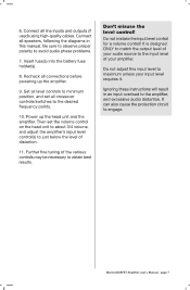
... instructions will result in this input level to the amplifier, and excessive audio distortion. Marine MOSFET Amplifier User's Manual - Connect all speakers, following the diagrams in an input overload to maximum unless your amplifier. Be sure to observe proper polarity to obtain best results. Then set ... may be necessary to avoid audio phase problems. 7. It can also cause the protection circuit to just below the level of your input level requires it. Recheck all crossover controls/switches to the input level of distortion. 11. Set all line inputs and outputs ...
... instructions will result in this input level to the amplifier, and excessive audio distortion. Marine MOSFET Amplifier User's Manual - Connect all speakers, following the diagrams in an input overload to maximum unless your amplifier. Be sure to observe proper polarity to obtain best results. Then set ... may be necessary to avoid audio phase problems. 7. It can also cause the protection circuit to just below the level of your input level requires it. Recheck all crossover controls/switches to the input level of distortion. 11. Set all line inputs and outputs ...
User Manual in English
Page 8
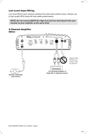
... control HIGH LEVEL INPUTS not used in this installation 0 000000 To L/R Audio Outputs of head unit or signal processor Marine MOSFET Amplifier User's Manual - Low Level Input Wiring Low-level (RCA) input wiring is preferred for best audio performance. PM. NOTE:Do not connectBOTH the ...high levelandlow levelinputs from your receiver to your amplifier at the same time! 2-Channel Amplifier MR800 1© 30.18...
... control HIGH LEVEL INPUTS not used in this installation 0 000000 To L/R Audio Outputs of head unit or signal processor Marine MOSFET Amplifier User's Manual - Low Level Input Wiring Low-level (RCA) input wiring is preferred for best audio performance. PM. NOTE:Do not connectBOTH the ...high levelandlow levelinputs from your receiver to your amplifier at the same time! 2-Channel Amplifier MR800 1© 30.18...

User Manual in English
Page 9
... Mode switch in 4CH Position HIGH LEVEL INPUTS not used in this installation Input Mode switch in this installation Remote subwoofer level control 4CH 2CH MODE 0 000000 To Front and Rear Audio Outputs of head unit or signal processor Marine MOSFET Amplifier User's Manual - ID I \_C O El 4CH 2CH INPUT MODE HIGH LEVEL INPUTS not...
... Mode switch in 4CH Position HIGH LEVEL INPUTS not used in this installation Input Mode switch in this installation Remote subwoofer level control 4CH 2CH MODE 0 000000 To Front and Rear Audio Outputs of head unit or signal processor Marine MOSFET Amplifier User's Manual - ID I \_C O El 4CH 2CH INPUT MODE HIGH LEVEL INPUTS not...
User Manual in English
Page 10
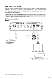
...:MIV SENSIMMY dm INPUTOF iripWrs' Remote subwoofer level control LOW LEVEL INPUTS not used when your amplifier at the same time! 2-Channel Amplifier MR800 MIME POWSt SIBWOCFER I 0 I Lo.w FL n. If the RCA outputs are not present, connect the speaker outputs from your receiver to... Marine MOSFET Amplifier User's Manual - R+ PURPLE GREEN BLACK 0 000000 To LEFT and RIGHT Speaker Terminals of the amplifier. High Level Input Wiring The high level input(s) should only be used in this installation L+ LWHITE BLUE R- Be sure to observe polarity to avoid audio phase problems. NOTE:Do not...
...:MIV SENSIMMY dm INPUTOF iripWrs' Remote subwoofer level control LOW LEVEL INPUTS not used when your amplifier at the same time! 2-Channel Amplifier MR800 MIME POWSt SIBWOCFER I 0 I Lo.w FL n. If the RCA outputs are not present, connect the speaker outputs from your receiver to... Marine MOSFET Amplifier User's Manual - R+ PURPLE GREEN BLACK 0 000000 To LEFT and RIGHT Speaker Terminals of the amplifier. High Level Input Wiring The high level input(s) should only be used in this installation L+ LWHITE BLUE R- Be sure to observe polarity to avoid audio phase problems. NOTE:Do not...
User Manual in English
Page 11
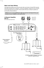
... the speaker outputs from your receiver to the high level input connector of head unit or signal processor Marine MOSFET Amplifier User's Manual - Be sure to observe polarity to avoid audio phase problems. NOTE:Do not connectBOTH the high levelandlowlevelinputs from the receiver to your amplifier at the same time! 4-Channel Amplifier MR1000 with... amplifier. O:ON 1111 i-"7 AEA _ IOW PPM MSS POOR PPR EPAL =env anr, :En INPUT MODE AMPLIFIER O13.• INPUTS O11.2 Input Mode switch in this installation -• '12 00b5.>---a--
... the speaker outputs from your receiver to the high level input connector of head unit or signal processor Marine MOSFET Amplifier User's Manual - Be sure to observe polarity to avoid audio phase problems. NOTE:Do not connectBOTH the high levelandlowlevelinputs from the receiver to your amplifier at the same time! 4-Channel Amplifier MR1000 with... amplifier. O:ON 1111 i-"7 AEA _ IOW PPM MSS POOR PPR EPAL =env anr, :En INPUT MODE AMPLIFIER O13.• INPUTS O11.2 Input Mode switch in this installation -• '12 00b5.>---a--
User Manual in English
Page 12
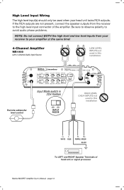
... same time! 4-Channel Amplifier MR1000 with 2-ChannelAudioInput Source LOW LEVEL INPUTS not used in this installation L+ LWHITE BLUE R- Be sure to observe polarity to avoid audio phase problems. NOTE:Do not connectBOTH the high levelandlowlevelinputs from the receiver to your head unit lacks RCA ...this installation Remote subwoofer level control ezMnMA.NAU3.Sn• af, • u goi.. - If the RCA outputs are not present, connect the speaker outputs from your receiver to the high level input connector of head unit or signal processor Marine MOSFET Amplifier User's Manual -...
... same time! 4-Channel Amplifier MR1000 with 2-ChannelAudioInput Source LOW LEVEL INPUTS not used in this installation L+ LWHITE BLUE R- Be sure to observe polarity to avoid audio phase problems. NOTE:Do not connectBOTH the high levelandlowlevelinputs from the receiver to your head unit lacks RCA ...this installation Remote subwoofer level control ezMnMA.NAU3.Sn• af, • u goi.. - If the RCA outputs are not present, connect the speaker outputs from your receiver to the high level input connector of head unit or signal processor Marine MOSFET Amplifier User's Manual -...
User Manual in English
Page 13
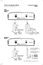
... Negative (-) terminal of the speaker to REMOTE TURN-ON ORANGE terminal of head unit RED I:- Power and Speaker Wiring 2 Channel and Bridged Modes 2-Channel Amplifier MR800 Two Channel Mode POWER CONNECTIONS SPEAKER OUTPUTS 0 0 BONS ....)marirow El CE Bridged Mode 9\ 1 BLACK = Chassis ground point 14/ -- to the L(+) amplifier lead. WHITE GREY/BLACK...
... Negative (-) terminal of the speaker to REMOTE TURN-ON ORANGE terminal of head unit RED I:- Power and Speaker Wiring 2 Channel and Bridged Modes 2-Channel Amplifier MR800 Two Channel Mode POWER CONNECTIONS SPEAKER OUTPUTS 0 0 BONS ....)marirow El CE Bridged Mode 9\ 1 BLACK = Chassis ground point 14/ -- to the L(+) amplifier lead. WHITE GREY/BLACK...

User Manual in English
Page 14
page 14 Power and Speaker Wiring 4 Channel Mode 4-Channel Amplifier MR1000 Four Channel Mode POWER CONNECTIONS SPEAKER OUTPUTS marine. El CE BLACK Chassis ground point to REMOTE TURN-ON ORANGE terminal of head unit RED FUSE Battery (provided) WHITE WHITE/ BLACK CH1 Speaker GREY GREY/ BLACK CH2 Speaker GREEN GREEN/ BLACK CH3 Speaker PURPLE PURPLE/ BLACK CH4 Speaker Marine MOSFET Amplifier User's Manual -
page 14 Power and Speaker Wiring 4 Channel Mode 4-Channel Amplifier MR1000 Four Channel Mode POWER CONNECTIONS SPEAKER OUTPUTS marine. El CE BLACK Chassis ground point to REMOTE TURN-ON ORANGE terminal of head unit RED FUSE Battery (provided) WHITE WHITE/ BLACK CH1 Speaker GREY GREY/ BLACK CH2 Speaker GREEN GREEN/ BLACK CH3 Speaker PURPLE PURPLE/ BLACK CH4 Speaker Marine MOSFET Amplifier User's Manual -

User Manual in English
Page 15
...) A Connect the CH1 (+) lead to the Subwoofer 2 (-) terminal. to the Subwoofer 2 (-F) terminal. page 15 Connect the CH4 (-) lead to the Subwoofer 1(+) terminal. Marine MOSFET Amplifier User's Manual - I=I I=I \ SUBWOOFER 1 SPEAKER IMPEDANCE 4-8 OHMS GREEN PURPLE/BLACK SUBWOOFER 2 SPEAKER IMPEDANCE 4-8 OHMS Connect the CH3 (+) lead to REMOTE TURN-ON ORANGE terminal of head unit RED...
...) A Connect the CH1 (+) lead to the Subwoofer 2 (-) terminal. to the Subwoofer 2 (-F) terminal. page 15 Connect the CH4 (-) lead to the Subwoofer 1(+) terminal. Marine MOSFET Amplifier User's Manual - I=I I=I \ SUBWOOFER 1 SPEAKER IMPEDANCE 4-8 OHMS GREEN PURPLE/BLACK SUBWOOFER 2 SPEAKER IMPEDANCE 4-8 OHMS Connect the CH3 (+) lead to REMOTE TURN-ON ORANGE terminal of head unit RED...
User Manual in English
Page 16
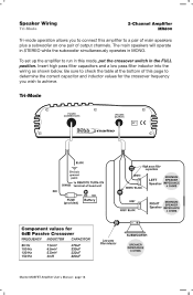
... Hz 150 Hz 7.5mH 6.5mH 5.5mH 4mH 470uF 330uF 330uF 220uF Low pass filter inductor SUBWOOFER SPEAKER IMPEDANCE 8 OHMS Marine MOSFET Amplifier User's Manual - To set up the amplifier to run in this amplifier to a pair of main speakers plus a subwoofer on one pair of output channels. Be ... values for the crossover frequency you to connect this mode, put the crossover switch in MONO. page 16 Speaker Wiring 2-Channel Amplifier MR800 Tri-mode operation allows you wish to achieve. The main speakers will operate in STEREO while the subwoofer simultaneously operates in the FULL position....
... Hz 150 Hz 7.5mH 6.5mH 5.5mH 4mH 470uF 330uF 330uF 220uF Low pass filter inductor SUBWOOFER SPEAKER IMPEDANCE 8 OHMS Marine MOSFET Amplifier User's Manual - To set up the amplifier to run in this amplifier to a pair of main speakers plus a subwoofer on one pair of output channels. Be ... values for the crossover frequency you to connect this mode, put the crossover switch in MONO. page 16 Speaker Wiring 2-Channel Amplifier MR800 Tri-mode operation allows you wish to achieve. The main speakers will operate in STEREO while the subwoofer simultaneously operates in the FULL position....

User Manual in English
Page 17
...›Trilkairiray. Be sure to check the table at the bottom of this mode, put the crossover switch in MONO. To set up the amplifier to run in this page to determine the correct capacitor and inductor values for 6dB Passive Crossover FREQUENCY INDUCTOR CAPACITOR...GREEN/ BLACK Speaker MINIMUM SPEAKER PURPLE IMPEDANCE CH4 4 OHMS PURPLE/ BLACK Speaker SPEAKER IMPEDANCE 8 OHMS Low pass filter inductor Marine MOSFET Amplifier User's Manual - El CE BLACK Chassis ground point to REMOTE TURN-ON ORANGE terminal of output channels. Insert high pass filter capacitors and a low pass...
...›Trilkairiray. Be sure to check the table at the bottom of this mode, put the crossover switch in MONO. To set up the amplifier to run in this page to determine the correct capacitor and inductor values for 6dB Passive Crossover FREQUENCY INDUCTOR CAPACITOR...GREEN/ BLACK Speaker MINIMUM SPEAKER PURPLE IMPEDANCE CH4 4 OHMS PURPLE/ BLACK Speaker SPEAKER IMPEDANCE 8 OHMS Low pass filter inductor Marine MOSFET Amplifier User's Manual - El CE BLACK Chassis ground point to REMOTE TURN-ON ORANGE terminal of output channels. Insert high pass filter capacitors and a low pass...
User Manual in English
Page 18
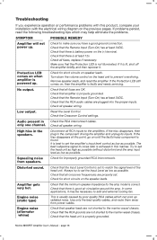
... operation or performance problems with this product, compare your installation with the electrical... Check the Crossover Control settings. Audio present in the component driving...User's Manual - If problems persist, read the following troubleshooting tips which can pick up . Check that all crossover frequencies are properly set...replace ifnecessary. Try to the amplifiers. Check that the Protection LED is faulty and needs servicing. Use only the best quality cables, and route them away from speakers. Check that speaker leads are plugged into the proper inputs. Troubleshooting...
... operation or performance problems with this product, compare your installation with the electrical... Check the Crossover Control settings. Audio present in the component driving...User's Manual - If problems persist, read the following troubleshooting tips which can pick up . Check that all crossover frequencies are properly set...replace ifnecessary. Try to the amplifiers. Check that the Protection LED is faulty and needs servicing. Use only the best quality cables, and route them away from speakers. Check that speaker leads are plugged into the proper inputs. Troubleshooting...
User Manual in English
Page 19
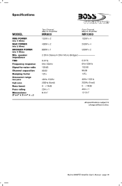
Specifications MODEL RISS POWER into 4 Ohms MAX POWER into 2 Ohms BRIDGED POWER Into 4 Ohms Min. Marine MOSFET Amplifier User's Manual - speaker Impedance THD Frequency response Signal-to-noise ratio Channel separation Damping factor Crossover range low pass high pass Bass boost Fuse rating Dimensions: (7-ais" x 2.1/4" x ...) Two Channel Marine Amplifier MR800 125W x 2 Four Channel Marine Amplifier MR1000...
Specifications MODEL RISS POWER into 4 Ohms MAX POWER into 2 Ohms BRIDGED POWER Into 4 Ohms Min. Marine MOSFET Amplifier User's Manual - speaker Impedance THD Frequency response Signal-to-noise ratio Channel separation Damping factor Crossover range low pass high pass Bass boost Fuse rating Dimensions: (7-ais" x 2.1/4" x ...) Two Channel Marine Amplifier MR800 125W x 2 Four Channel Marine Amplifier MR1000...


