
Owners Guide
Page 1
The Bose® Lifestyle® SA-2 and SA-3 Stereo Amplifier Owner's Guide Guía del usuario Notice d'utilisation
The Bose® Lifestyle® SA-2 and SA-3 Stereo Amplifier Owner's Guide Guía del usuario Notice d'utilisation
Owners Guide
Page 5
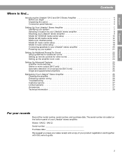
..., and purchase date. Model: SA2 SA3 Serial number Purchase date We suggest you begin 4 Unpacking the carton 4 Connection panel features 5 Setting Up Your Lifestyle® Stereo Amplifier 7 Identifying your system 7 Selecting a location for your Lifestyle® stereo amplifier 8 Mounting your Lifestyle® stereo amplifier. Introducing the Lifestyle® SA-2 and SA-3 Stereo Amplifier 4 Before you keep your sales receipt...
..., and purchase date. Model: SA2 SA3 Serial number Purchase date We suggest you begin 4 Unpacking the carton 4 Connection panel features 5 Setting Up Your Lifestyle® Stereo Amplifier 7 Identifying your system 7 Selecting a location for your Lifestyle® stereo amplifier 8 Mounting your Lifestyle® stereo amplifier. Introducing the Lifestyle® SA-2 and SA-3 Stereo Amplifier 4 Before you keep your sales receipt...
Owners Guide
Page 6
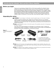
...your system, you for international use with your Lifestyle® stereo amplifier. If any way. By using the Lifestyle® stereo amplifier to -9-pin DIN adapter 20-ft Bose® link A cable *The Lifestyle® stereo amplifier includes a 120V AC (mains) power cord for use in... the shipping carton for correct phone numbers. Note: The Lifestyle® stereo amplifier is designed for assistance. Bose proprietary Integrated Signal Processing technology, featured in the amplifier, provides full, rich stereo sound, even when the speakers are playing at low volumes. Note: Use...
...your system, you for international use with your Lifestyle® stereo amplifier. If any way. By using the Lifestyle® stereo amplifier to -9-pin DIN adapter 20-ft Bose® link A cable *The Lifestyle® stereo amplifier includes a 120V AC (mains) power cord for use in... the shipping carton for correct phone numbers. Note: The Lifestyle® stereo amplifier is designed for assistance. Bose proprietary Integrated Signal Processing technology, featured in the amplifier, provides full, rich stereo sound, even when the speakers are playing at low volumes. Note: Use...
Owners Guide
Page 7
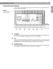
... into an AC (mains) receptacle. 2 VCA Local volume control connections. Contact your Bose® dealer or call Bose Customer Service for information on installing this guide. 3 SPEAKER OUTPUTS Left and right amplifier speaker outputs. Figure 2 Lifestyle® amplifier connection panel 1 2 3 4 5 6 7 1 AC POWER AC power cord connector...this product. Power is applied when the power cord is required. English Introducing the Lifestyle® SA-2 and SA-3 Stereo Amplifier Connection panel features The connection panel includes the input/output connections plus room code switches and...
... into an AC (mains) receptacle. 2 VCA Local volume control connections. Contact your Bose® dealer or call Bose Customer Service for information on installing this guide. 3 SPEAKER OUTPUTS Left and right amplifier speaker outputs. Figure 2 Lifestyle® amplifier connection panel 1 2 3 4 5 6 7 1 AC POWER AC power cord connector...this product. Power is applied when the power cord is required. English Introducing the Lifestyle® SA-2 and SA-3 Stereo Amplifier Connection panel features The connection panel includes the input/output connections plus room code switches and...
Owners Guide
Page 8
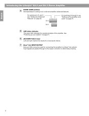
... SA-3 Stereo Amplifier ROOM CODE switches 4 Microswitches for connecting the amplifier to allow daisy chaining. 6 For switches A, B, and C, see "Setting up your system" on page 25. SA-2 5 LED status indicator The green LED indicates the operational state of the amplifier. See "Powering-up the amplifier room code...on page 21. 6 AUX INPUT (SA-3 only) Left and right channel line inputs for a local audio device. 7 Bose® link INPUT/OUTPUT Nine-pin DIN connectors used for setting room code and amplifier advanced features. SA-3 For switches 6 through to the output connector to...
... SA-3 Stereo Amplifier ROOM CODE switches 4 Microswitches for connecting the amplifier to allow daisy chaining. 6 For switches A, B, and C, see "Setting up your system" on page 25. SA-2 5 LED status indicator The green LED indicates the operational state of the amplifier. See "Powering-up the amplifier room code...on page 21. 6 AUX INPUT (SA-3 only) Left and right channel line inputs for a local audio device. 7 Bose® link INPUT/OUTPUT Nine-pin DIN connectors used for setting room code and amplifier advanced features. SA-3 For switches 6 through to the output connector to...

Owners Guide
Page 9
...174; see "Model AV-28 media center setup" on page 10. This section provides placement and mounting instructions for the Lifestyle® stereo amplifier. The product label on whether you have . Model 5 music center Note: If you are planning to use this information you will need..."Model 20 music center setup" on page 18. English Setting Up Your Lifestyle® Stereo Amplifier Identifying your particular home entertainment system. The set up the amplifier with your system The Lifestyle® stereo amplifier and additional remote come ready to be installed and used in the...
...174; see "Model AV-28 media center setup" on page 10. This section provides placement and mounting instructions for the Lifestyle® stereo amplifier. The product label on whether you have . Model 5 music center Note: If you are planning to use this information you will need..."Model 20 music center setup" on page 18. English Setting Up Your Lifestyle® Stereo Amplifier Identifying your particular home entertainment system. The set up the amplifier with your system The Lifestyle® stereo amplifier and additional remote come ready to be installed and used in the...

Owners Guide
Page 10
... than 104°F (45°C). • For optimum performance, place the amplifier in a well-ventilated area. • DO NOT place the amplifier in a completely enclosed area. English Setting Up Your Lifestyle® Stereo Amplifier Selecting a location for your Lifestyle® stereo amplifier Your Lifestyle® stereo amplifier does not need to be used indoors. If adequate ventilation is...
... than 104°F (45°C). • For optimum performance, place the amplifier in a well-ventilated area. • DO NOT place the amplifier in a completely enclosed area. English Setting Up Your Lifestyle® Stereo Amplifier Selecting a location for your Lifestyle® stereo amplifier Your Lifestyle® stereo amplifier does not need to be used indoors. If adequate ventilation is...

Owners Guide
Page 11
...Stereo Amplifier Mounting your Lifestyle® stereo amplifier Your Lifestyle® stereo amplifier can be placed on a shelf or mounted on a wall (Figure 3). • When placing the amplifier on a horizontal surface like a floor or shelf, the amplifier's rubber feet provide stability and prevent scratches. • ONLY when mounting the amplifier... (4) #10 (M5) 3/8 in (0.95 cm) minimum To mark mounting hole locations, remove the rubber feet, hold the amplifier in position, and mark the wall through the clearance holes in Figure 3. Figure 3 Installation options Connector panel on the left...
...Stereo Amplifier Mounting your Lifestyle® stereo amplifier Your Lifestyle® stereo amplifier can be placed on a shelf or mounted on a wall (Figure 3). • When placing the amplifier on a horizontal surface like a floor or shelf, the amplifier's rubber feet provide stability and prevent scratches. • ONLY when mounting the amplifier... (4) #10 (M5) 3/8 in (0.95 cm) minimum To mark mounting hole locations, remove the rubber feet, hold the amplifier in position, and mark the wall through the clearance holes in Figure 3. Figure 3 Installation options Connector panel on the left...
Owners Guide
Page 12
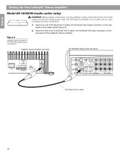
... panel AV-18/38/48 media center rear panel BoseLink OUTPUT BoseLink INPUT 20-ft Bose® link A cable 10 English Setting Up Your Lifestyle® Stereo Amplifier Model AV-18/38/48 media center setup CAUTION: Before making connections, turn the Lifestyle® system off and disconnect the ... the AC (mains) power outlet. Insert the other connections. 1. Insert one end of the Bose® link A cable into the Bose® link input connector on the rear panel of the Lifestyle® stereo amplifier. DO NOT plug the amplifier into an outlet until you have completed all other end of the...
... panel AV-18/38/48 media center rear panel BoseLink OUTPUT BoseLink INPUT 20-ft Bose® link A cable 10 English Setting Up Your Lifestyle® Stereo Amplifier Model AV-18/38/48 media center setup CAUTION: Before making connections, turn the Lifestyle® system off and disconnect the ... the AC (mains) power outlet. Insert the other connections. 1. Insert one end of the Bose® link A cable into the Bose® link input connector on the rear panel of the Lifestyle® stereo amplifier. DO NOT plug the amplifier into an outlet until you have completed all other end of the...

Owners Guide
Page 13
...Bose® link. Select the Audio tab and navigate down to work with your main room remote. To make sure that this : 1. Press the Exit button on page 22. See "Setting Up Additional Rooms For Sound" on the remote. 11 English Figure 6 Remote microswitches Setting Up Your Lifestyle® Stereo Amplifier...the house code settings (switches 1, 2, 3, and 4) match the house code settings in your system For the Lifestyle® stereo amplifier to Expansion Protocol. 4. House code switches must match main room remote ON Check the expansion protocol setting in your home entertainment ...
...Bose® link. Select the Audio tab and navigate down to work with your main room remote. To make sure that this : 1. Press the Exit button on page 22. See "Setting Up Additional Rooms For Sound" on the remote. 11 English Figure 6 Remote microswitches Setting Up Your Lifestyle® Stereo Amplifier...the house code settings (switches 1, 2, 3, and 4) match the house code settings in your system For the Lifestyle® stereo amplifier to Expansion Protocol. 4. House code switches must match main room remote ON Check the expansion protocol setting in your home entertainment ...
Owners Guide
Page 14
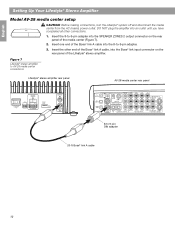
Insert the 8-to-9-pin adapter into the 8-to -9-pin DIN adapter 20-ft Bose® link A cable 12 Insert one end of the media center (Figure 7). 2. Figure 7 Lifestyle® stereo amplifier to AV-28 media center connections Lifestyle® stereo amplifier rear panel AV-28 media center rear panel BoseLink OUTPUT BoseLink INPUT 8-to -9-pin adapter...
Insert the 8-to-9-pin adapter into the 8-to -9-pin DIN adapter 20-ft Bose® link A cable 12 Insert one end of the media center (Figure 7). 2. Figure 7 Lifestyle® stereo amplifier to AV-28 media center connections Lifestyle® stereo amplifier rear panel AV-28 media center rear panel BoseLink OUTPUT BoseLink INPUT 8-to -9-pin adapter...
Owners Guide
Page 15
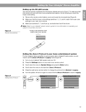
... that the house code settings (switches 1, 2, 3, and 4) match the house code settings in your home entertainment system For the Lifestyle® stereo amplifier to work with a Lifestyle® media center, you will need to set up for more than one room. English Figure 8 Remote microswitches Setting... Up Your Lifestyle® Stereo Amplifier Setting up the RC-28S remote Your second remote is reset to Legacy mode (Figure 9). 1. Make sure that the Zone 2 Protocol is...
... that the house code settings (switches 1, 2, 3, and 4) match the house code settings in your home entertainment system For the Lifestyle® stereo amplifier to work with a Lifestyle® media center, you will need to set up for more than one room. English Figure 8 Remote microswitches Setting... Up Your Lifestyle® Stereo Amplifier Setting up the RC-28S remote Your second remote is reset to Legacy mode (Figure 9). 1. Make sure that the Zone 2 Protocol is...

Owners Guide
Page 16
... one of the unused ROOM output connectors (B, C, or D) on the rear panel of the Bose® link A cable into one end of the Lifestyle® stereo amplifier. Figure 10 Lifestyle® stereo amplifier to multi-room interface connections Lifestyle® stereo amplifier rear panel Multi-room interface rear panel BoseLink OUTPUT BoseLink INPUT 8-to -9-pin adapter. 3. Insert...
... one of the unused ROOM output connectors (B, C, or D) on the rear panel of the Bose® link A cable into one end of the Lifestyle® stereo amplifier. Figure 10 Lifestyle® stereo amplifier to multi-room interface connections Lifestyle® stereo amplifier rear panel Multi-room interface rear panel BoseLink OUTPUT BoseLink INPUT 8-to -9-pin adapter. 3. Insert...

Owners Guide
Page 17
... to control up to four sets of speakers. Note: Refer to your system in individual rooms. These rooms are connected to as one room of Bose® powered speakers placed in more rooms are referred to your system, the Personal® music center displays ROOM and HOUSE buttons, and room indicators... for setting up the Personal® music center for the first time. English Figure 11 Sample display for a tworoom system Setting Up Your Lifestyle® Stereo Amplifier Setting up the Personal® music center Systems that share a source.
... to control up to four sets of speakers. Note: Refer to your system in individual rooms. These rooms are connected to as one room of Bose® powered speakers placed in more rooms are referred to your system, the Personal® music center displays ROOM and HOUSE buttons, and room indicators... for setting up the Personal® music center for the first time. English Figure 11 Sample display for a tworoom system Setting Up Your Lifestyle® Stereo Amplifier Setting up the Personal® music center Systems that share a source.
Owners Guide
Page 18
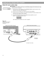
...; link A cable into the SPEAKER ZONES 2 output connector on the rear panel of the Lifestyle® stereo amplifier to -9-pin DIN adapter 20-ft Bose® link A cable 16 Insert the 8-to-9-in DIN adapter into the 8-to Model 20 music center connections See "Setting up , switches 6, ... (mains) power outlet. Set the ROOM CODE switches of the Lifestyle® stereo amplifier. 4. DO NOT plug the amplifier into an outlet until you have ® completed all other end of the Bose® link A cable into the Bose® link input connector on the rear panel of the music center (Figure...
...; link A cable into the SPEAKER ZONES 2 output connector on the rear panel of the Lifestyle® stereo amplifier to -9-pin DIN adapter 20-ft Bose® link A cable 16 Insert the 8-to-9-in DIN adapter into the 8-to Model 20 music center connections See "Setting up , switches 6, ... (mains) power outlet. Set the ROOM CODE switches of the Lifestyle® stereo amplifier. 4. DO NOT plug the amplifier into an outlet until you have ® completed all other end of the Bose® link A cable into the Bose® link input connector on the rear panel of the music center (Figure...

Owners Guide
Page 19
English Figure 13 RC-20 remote Zone 2 switch settings Setting Up Your Lifestyle® Stereo Amplifier Setting up the RC-20 remote for more information on operating your system in your system uses a Model 20 music center, you need to set ...
English Figure 13 RC-20 remote Zone 2 switch settings Setting Up Your Lifestyle® Stereo Amplifier Setting up the RC-20 remote for more information on operating your system in your system uses a Model 20 music center, you need to set ...
Owners Guide
Page 20
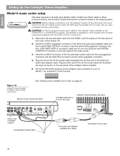
...music center from the FIXED OUTPUT connectors. 1. Set the ROOM CODE switches of the Lifestyle® stereo amplifier to the SPEAKERS A or SPEAKERS B outputs. Disconnect the Acoustimass® cable from Bose) 20-ft Bose® link A cable 18 See "Setting up , switches 6, 8 and 9 down). DO ...) FIXED OUTPUT connector. Plug one end of the 20-foot audio cable (supplied) into the Bose® link input connector on page 24. English Setting Up Your Lifestyle® Stereo Amplifier Model 5 music center setup This setup requires a 3-ft audio input adapter cable. Contact your...
...music center from the FIXED OUTPUT connectors. 1. Set the ROOM CODE switches of the Lifestyle® stereo amplifier to the SPEAKERS A or SPEAKERS B outputs. Disconnect the Acoustimass® cable from Bose) 20-ft Bose® link A cable 18 See "Setting up , switches 6, 8 and 9 down). DO ...) FIXED OUTPUT connector. Plug one end of the 20-foot audio cable (supplied) into the Bose® link input connector on page 24. English Setting Up Your Lifestyle® Stereo Amplifier Model 5 music center setup This setup requires a 3-ft audio input adapter cable. Contact your...
Owners Guide
Page 21
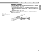
English Figure 15 RC-5 remote switch settings Setting Up Your Lifestyle® Stereo Amplifier Setting up the RC-5 remote If your system uses a Model 5 music center, you need to set up (on operating your system in your first remote. 3. ...Slide switch 5 down (off) and 6 up a second RC-5 remote control to your Lifestyle® stereo amplifier. 1. Remove the remote control battery cover and locate the miniature switches (Figure 15). 2. Note: Refer to operate your Lifestyle® system owner's guide for more...
English Figure 15 RC-5 remote switch settings Setting Up Your Lifestyle® Stereo Amplifier Setting up the RC-5 remote If your system uses a Model 5 music center, you need to set up (on operating your system in your first remote. 3. ...Slide switch 5 down (off) and 6 up a second RC-5 remote control to your Lifestyle® stereo amplifier. 1. Remove the remote control battery cover and locate the miniature switches (Figure 15). 2. Note: Refer to operate your Lifestyle® system owner's guide for more...

Owners Guide
Page 22
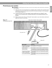
...lengths, see "Wire recommendations" on the rear panel of the Lifestyle® stereo amplifier. One wire is usually marked (striped, collared, or ribbed), indicating that the amplifier is disconnected from the SPEAKER OUTPUTS connector on page 28. 1. Connect the ... of Lifestyle® stereo amplifier Positive (+) wire (marked with stripe) Terminal block connector 20 CAUTION: The Lifestyle® stereo amplifier requires a 6-ohm minimum load. English Setting Up Your Lifestyle® Stereo Amplifier Connecting speakers to your Lifestyle® stereo amplifier CAUTION: DO NOT ...
...lengths, see "Wire recommendations" on the rear panel of the Lifestyle® stereo amplifier. One wire is usually marked (striped, collared, or ribbed), indicating that the amplifier is disconnected from the SPEAKER OUTPUTS connector on page 28. 1. Connect the ... of Lifestyle® stereo amplifier Positive (+) wire (marked with stripe) Terminal block connector 20 CAUTION: The Lifestyle® stereo amplifier requires a 6-ohm minimum load. English Setting Up Your Lifestyle® Stereo Amplifier Connecting speakers to your Lifestyle® stereo amplifier CAUTION: DO NOT ...
Owners Guide
Page 23
Using the power cord included with your Personal® music center or your new remote control and adjust the volume to your Lifestyle® stereo amplifier, firmly insert the small connector on the rear panel of the power cord into an AC (mains) outlet until all other connections are ... ON and receiving data commands from the media center through the Bose® link port. The amplifier is set up as a supplemental amplifier and it is OFF. Connect the power cord of the Lifestyle® stereo amplifier and your system CAUTION: DO NOT plug the AC power cord into the AC power...
Using the power cord included with your Personal® music center or your new remote control and adjust the volume to your Lifestyle® stereo amplifier, firmly insert the small connector on the rear panel of the power cord into an AC (mains) outlet until all other connections are ... ON and receiving data commands from the media center through the Bose® link port. The amplifier is set up as a supplemental amplifier and it is OFF. Connect the power cord of the Lifestyle® stereo amplifier and your system CAUTION: DO NOT plug the AC power cord into the AC power...
