
Owners Guide
Page 1
The Bose® Lifestyle® SA-2 and SA-3 Stereo Amplifier Owner's Guide Guía del usuario Notice d'utilisation
The Bose® Lifestyle® SA-2 and SA-3 Stereo Amplifier Owner's Guide Guía del usuario Notice d'utilisation
Owners Guide
Page 3
... be connected to the grounding system of the building, as close to the point of cable entry as is provided to call Bose to correct the interference by Bose® Corporation. When a cart is damaged; Servicing is required when the apparatus has been damaged in your safety. liquid has... power lines or circuits, as power-supply cord or plug is used in a wet basement, near overhead power lines or other apparatus (including amplifiers) that the cable ground shall be determined by turning the equipment off and on, you to comply with the instructions, may touch dangerous voltage...
... be connected to the grounding system of the building, as close to the point of cable entry as is provided to call Bose to correct the interference by Bose® Corporation. When a cart is damaged; Servicing is required when the apparatus has been damaged in your safety. liquid has... power lines or circuits, as power-supply cord or plug is used in a wet basement, near overhead power lines or other apparatus (including amplifiers) that the cable ground shall be determined by turning the equipment off and on, you to comply with the instructions, may touch dangerous voltage...
Owners Guide
Page 5
... together with this owner's guide. 3 Model: SA2 SA3 Serial number Purchase date We suggest you begin 4 Unpacking the carton 4 Connection panel features 5 Setting Up Your Lifestyle® Stereo Amplifier 7 Identifying your system 7 Selecting a location for your Lifestyle® stereo amplifier 8 Mounting your Lifestyle® stereo amplifier 9 Model AV-18/38/48 media center setup...
... together with this owner's guide. 3 Model: SA2 SA3 Serial number Purchase date We suggest you begin 4 Unpacking the carton 4 Connection panel features 5 Setting Up Your Lifestyle® Stereo Amplifier 7 Identifying your system 7 Selecting a location for your Lifestyle® stereo amplifier 8 Mounting your Lifestyle® stereo amplifier 9 Model AV-18/38/48 media center setup...
Owners Guide
Page 6
...out of the reach of the product appears to be damaged, do not attempt to -9-pin DIN adapter 20-ft Bose® link A cable *The Lifestyle® stereo amplifier includes a 120V AC (mains) power cord for use in the appropriate blank on page 3. If the power cord...original packing materials provide the safest way to your authorized Bose dealer immediately, or call Bose Customer Service. You may need them later. The Lifestyle® stereo amplifier provides you want to add Bose® non-powered environmental speakers or Bose non-powered accessory speakers to transport this product. If ...
...out of the reach of the product appears to be damaged, do not attempt to -9-pin DIN adapter 20-ft Bose® link A cable *The Lifestyle® stereo amplifier includes a 120V AC (mains) power cord for use in the appropriate blank on page 3. If the power cord...original packing materials provide the safest way to your authorized Bose dealer immediately, or call Bose Customer Service. You may need them later. The Lifestyle® stereo amplifier provides you want to add Bose® non-powered environmental speakers or Bose non-powered accessory speakers to transport this product. If ...
Owners Guide
Page 7
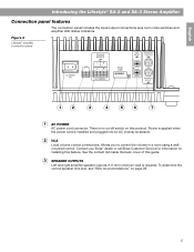
... control. To determine the correct speaker wire size, see "Wire recommendations" on installing this feature. Figure 2 Lifestyle® amplifier connection panel 1 2 3 4 5 6 7 1 AC POWER AC power cord connector. Contact your Bose® dealer or call Bose Customer Service for information on page 28. 5 Power is applied when the power cord is required. A 6-ohm minimum...
... control. To determine the correct speaker wire size, see "Wire recommendations" on installing this feature. Figure 2 Lifestyle® amplifier connection panel 1 2 3 4 5 6 7 1 AC POWER AC power cord connector. Contact your Bose® dealer or call Bose Customer Service for information on page 28. 5 Power is applied when the power cord is required. A 6-ohm minimum...
Owners Guide
Page 8
...CODE switches 4 Microswitches for connecting the amplifier to allow daisy chaining. 6 Input signals are passed through 9, see "Setting Up Advanced Features" on page 21. 6 AUX INPUT (SA-3 only) Left and right channel line inputs for a local audio device. 7 Bose® link INPUT/OUTPUT Nine-pin DIN... connectors used for setting room code and amplifier advanced features. For switches A, B, and C, see "Setting up your system" on page 25. SA-2 5 LED...
...CODE switches 4 Microswitches for connecting the amplifier to allow daisy chaining. 6 Input signals are passed through 9, see "Setting Up Advanced Features" on page 21. 6 AUX INPUT (SA-3 only) Left and right channel line inputs for a local audio device. 7 Bose® link INPUT/OUTPUT Nine-pin DIN... connectors used for setting room code and amplifier advanced features. For switches A, B, and C, see "Setting up your system" on page 25. SA-2 5 LED...

Owners Guide
Page 9
...music center setup" on the bottom panel identifies the model you have . See "Setting Up Additional Rooms For Sound" on page 10. Following this amplifier beyond a second room, you will need depends on page 16. Model 5 music center Note: If you are planning to use this information you will...music center setup" on whether you have a media center, music center, or multi-room interface. The set up the amplifier with your system The Lifestyle® stereo amplifier and additional remote come ready to change some switch settings in a second room (Room B). Model AV-18/38/48 media...
...music center setup" on the bottom panel identifies the model you have . See "Setting Up Additional Rooms For Sound" on page 10. Following this amplifier beyond a second room, you will need depends on page 16. Model 5 music center Note: If you are planning to use this information you will...music center setup" on whether you have a media center, music center, or multi-room interface. The set up the amplifier with your system The Lifestyle® stereo amplifier and additional remote come ready to change some switch settings in a second room (Room B). Model AV-18/38/48 media...

Owners Guide
Page 10
... It is neither designed nor tested for your Lifestyle® system or the accessory speakers. CAUTION: DO NOT mount the amplifier on boats. • Locate the amplifier indoors and within the reach of fine furniture. Like all electrical equipment, it generates some heat. • DO NOT use... outdoors, in recreational vehicles, or on surfaces that are not sturdy enough, or that the amplifier is located within 8 feet (2.5 m) of a power outlet. • Make sure that have hazards concealed behind them, such as the finished surface...
... It is neither designed nor tested for your Lifestyle® system or the accessory speakers. CAUTION: DO NOT mount the amplifier on boats. • Locate the amplifier indoors and within the reach of fine furniture. Like all electrical equipment, it generates some heat. • DO NOT use... outdoors, in recreational vehicles, or on surfaces that are not sturdy enough, or that the amplifier is located within 8 feet (2.5 m) of a power outlet. • Make sure that have hazards concealed behind them, such as the finished surface...

Owners Guide
Page 11
... and hardware Shelf placement Vertically mounted on wall Horizontally mounted on a wall, ALWAYS mount the amplifier in an orientation shown in the amplifier's enclosure for recommended mounting methods and hardware. • When mounting the amplifier vertically or horizontally on wall Wood wall /3 32 in (2.25 mm) (4) #10 x ...in (M5 x 75 mm) (4) #10 (M5) 3/8 in (0.95 cm) minimum To mark mounting hole locations, remove the rubber feet, hold the amplifier in position, and mark the wall through the clearance holes in the housing. 9 English Setting Up Your Lifestyle® Stereo...
... and hardware Shelf placement Vertically mounted on wall Horizontally mounted on a wall, ALWAYS mount the amplifier in an orientation shown in the amplifier's enclosure for recommended mounting methods and hardware. • When mounting the amplifier vertically or horizontally on wall Wood wall /3 32 in (2.25 mm) (4) #10 x ...in (M5 x 75 mm) (4) #10 (M5) 3/8 in (0.95 cm) minimum To mark mounting hole locations, remove the rubber feet, hold the amplifier in position, and mark the wall through the clearance holes in the housing. 9 English Setting Up Your Lifestyle® Stereo...
Owners Guide
Page 12
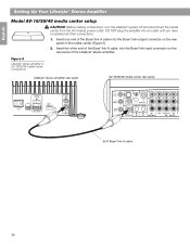
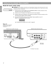
...38/48 media center rear panel BoseLink OUTPUT BoseLink INPUT 20-ft Bose® link A cable 10 DO NOT plug the amplifier into an outlet until you have completed all other end of the Bose® link A cable, into the Bose® link output connector on the rear panel of the media ...center (Figure 5). 2. English Setting Up Your Lifestyle® Stereo Amplifier Model AV-18/38/48 media center setup CAUTION: Before making connections,...
...38/48 media center rear panel BoseLink OUTPUT BoseLink INPUT 20-ft Bose® link A cable 10 DO NOT plug the amplifier into an outlet until you have completed all other end of the Bose® link A cable, into the Bose® link output connector on the rear panel of the media ...center (Figure 5). 2. English Setting Up Your Lifestyle® Stereo Amplifier Model AV-18/38/48 media center setup CAUTION: Before making connections,...

Owners Guide
Page 13
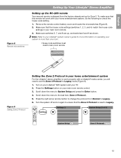
... that the house code settings (switches 1, 2, 3, and 4) match the house code settings in your system For the Lifestyle® stereo amplifier to work with your home entertainment system, the expansion protocol menu item must match main room remote ON Check the expansion protocol setting in your... (Figure 6). 2. English Figure 6 Remote microswitches Setting Up Your Lifestyle® Stereo Amplifier Setting up RC-18S and RC-38S remotes Your additional remote is shipped from the factory already set to Bose® link. Press the Exit button on page 22. House code switches must be...
... that the house code settings (switches 1, 2, 3, and 4) match the house code settings in your system For the Lifestyle® stereo amplifier to work with your home entertainment system, the expansion protocol menu item must match main room remote ON Check the expansion protocol setting in your... (Figure 6). 2. English Figure 6 Remote microswitches Setting Up Your Lifestyle® Stereo Amplifier Setting up RC-18S and RC-38S remotes Your additional remote is shipped from the factory already set to Bose® link. Press the Exit button on page 22. House code switches must be...
Owners Guide
Page 14
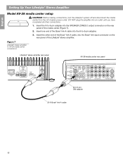
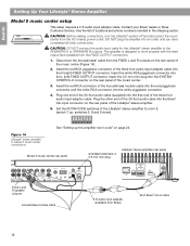
...® Stereo Amplifier Model AV-28 media center setup CAUTION: Before making connections, turn the Lifestyle® system off and disconnect the media center from the AC (mains) power outlet. Insert the other connections. 1. Insert one end of the Bose® link A cable into the Bose® link ...input connector on the rear panel of the media center (Figure 7). 2. DO NOT plug the amplifier into the SPEAKER ZONES 2 output connector on the rear panel of the...
...® Stereo Amplifier Model AV-28 media center setup CAUTION: Before making connections, turn the Lifestyle® system off and disconnect the media center from the AC (mains) power outlet. Insert the other connections. 1. Insert one end of the Bose® link A cable into the Bose® link ...input connector on the rear panel of the media center (Figure 7). 2. DO NOT plug the amplifier into the SPEAKER ZONES 2 output connector on the rear panel of the...
Owners Guide
Page 15
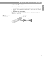
...down the menu to Legacy. 13 Turn the system off and on operating your system in your home entertainment system For the Lifestyle® stereo amplifier to work with a Lifestyle® media center, you will need to set up , and switches 6 and 9 are up for more ...4) match the house code settings in more than one room. Note: Refer to Legacy. 6. English Figure 8 Remote microswitches Setting Up Your Lifestyle® Stereo Amplifier Setting up the RC-28S remote Your second remote is reset to System Setup and press the Enter button. 4. Remove the remote control battery cover...
...down the menu to Legacy. 13 Turn the system off and on operating your system in your home entertainment system For the Lifestyle® stereo amplifier to work with a Lifestyle® media center, you will need to set up , and switches 6 and 9 are up for more ...4) match the house code settings in more than one room. Note: Refer to Legacy. 6. English Figure 8 Remote microswitches Setting Up Your Lifestyle® Stereo Amplifier Setting up the RC-28S remote Your second remote is reset to System Setup and press the Enter button. 4. Remove the remote control battery cover...

Owners Guide
Page 16
...-9-pin adapter into one end of the Bose® link A cable into the Bose® link input connector on the rear of the Lifestyle® stereo amplifier. Figure 10 Lifestyle® stereo amplifier to multi-room interface connections Lifestyle® stereo amplifier rear panel Multi-room interface rear panel...an outlet until you have completed all other end of the Bose® link A cable, into the 8-to -9-pin DIN adapter 20-ft Bose® link A cable 14 English Setting Up Your Lifestyle® Stereo Amplifier Multi-room interface setup CAUTION: Before making any connections, turn ...
...-9-pin adapter into one end of the Bose® link A cable into the Bose® link input connector on the rear of the Lifestyle® stereo amplifier. Figure 10 Lifestyle® stereo amplifier to multi-room interface connections Lifestyle® stereo amplifier rear panel Multi-room interface rear panel...an outlet until you have completed all other end of the Bose® link A cable, into the 8-to -9-pin DIN adapter 20-ft Bose® link A cable 14 English Setting Up Your Lifestyle® Stereo Amplifier Multi-room interface setup CAUTION: Before making any connections, turn ...

Owners Guide
Page 17
... 11 Sample display for a two-room system. Figure 11 shows a sample display for a tworoom system Setting Up Your Lifestyle® Stereo Amplifier Setting up the Personal® music center for more than one -room system). Note: Refer to control more rooms that have a multi-room...are connected to four sets of speakers. Selecting other rooms with room A being the primary room (the one used for a one room of Bose® powered speakers placed in more information on operating your system, the Personal® music center displays ROOM and HOUSE buttons, and room indicators ...
... 11 Sample display for a two-room system. Figure 11 shows a sample display for a tworoom system Setting Up Your Lifestyle® Stereo Amplifier Setting up the Personal® music center for more than one -room system). Note: Refer to control more rooms that have a multi-room...are connected to four sets of speakers. Selecting other rooms with room A being the primary room (the one used for a one room of Bose® powered speakers placed in more information on operating your system, the Personal® music center displays ROOM and HOUSE buttons, and room indicators ...
Owners Guide
Page 18
Insert one end of the Bose® link A cable into the Bose® link input connector on page 24. Insert the other connections. 1. Lifestyle® stereo amplifier rear panel Model 20 music center rear panel BoseLink OUTPUT BoseLink INPUT 8-to -9-pin adapter. 3. Set the ROOM CODE switches... , switches 6, 8 and 9 down). DO NOT plug the amplifier into the SPEAKER ZONES 2 output connector on the rear panel of the Lifestyle® stereo amplifier to room E (switch 7 up the amplifier room code" on the rear panel of the Bose® link A cable into the 8-to -9-pin DIN adapter ...
Insert one end of the Bose® link A cable into the Bose® link input connector on page 24. Insert the other connections. 1. Lifestyle® stereo amplifier rear panel Model 20 music center rear panel BoseLink OUTPUT BoseLink INPUT 8-to -9-pin adapter. 3. Set the ROOM CODE switches... , switches 6, 8 and 9 down). DO NOT plug the amplifier into the SPEAKER ZONES 2 output connector on the rear panel of the Lifestyle® stereo amplifier to room E (switch 7 up the amplifier room code" on the rear panel of the Bose® link A cable into the 8-to -9-pin DIN adapter ...

Owners Guide
Page 19
... control battery cover and locate the miniature switches (Figure 13). 2. English Figure 13 RC-20 remote Zone 2 switch settings Setting Up Your Lifestyle® Stereo Amplifier Setting up the RC-20 remote for Zone 2 If your system uses a Model 20 music center, you need to set up (on operating your system...
... control battery cover and locate the miniature switches (Figure 13). 2. English Figure 13 RC-20 remote Zone 2 switch settings Setting Up Your Lifestyle® Stereo Amplifier Setting up the RC-20 remote for Zone 2 If your system uses a Model 20 music center, you need to set up (on operating your system...
Owners Guide
Page 20
... (Figure 14). 2. Plug the other connections. Figure 14 Lifestyle® stereo amplifier to work properly with the fixed output level available from Bose) 20-ft Bose® link A cable 18 The amplifier is designed to Model 5 music center connections Model 5 music center rear panel SYSTEM...OUTPUT connector. Insert the red RCA piggyback connector of the Lifestyle® stereo amplifier to the SPEAKERS A or SPEAKERS B outputs. Contact your Bose® dealer or Bose Customer Service. DO NOT plug the amplifier into the SYSTEM CONTROL 2 connector on page 24. Insert the 3.5 mm...
... (Figure 14). 2. Plug the other connections. Figure 14 Lifestyle® stereo amplifier to work properly with the fixed output level available from Bose) 20-ft Bose® link A cable 18 The amplifier is designed to Model 5 music center connections Model 5 music center rear panel SYSTEM...OUTPUT connector. Insert the red RCA piggyback connector of the Lifestyle® stereo amplifier to the SPEAKERS A or SPEAKERS B outputs. Contact your Bose® dealer or Bose Customer Service. DO NOT plug the amplifier into the SYSTEM CONTROL 2 connector on page 24. Insert the 3.5 mm...
Owners Guide
Page 21
Note: Refer to operate your Lifestyle® stereo amplifier. 1. Remove the remote control battery cover and locate the miniature switches (Figure 15). 2. Slide switch 5 down (off) and 6 up a second RC-5 remote control to your ... the house code settings (switches 1, 2, 3, and 4) match those in more information on ). English Figure 15 RC-5 remote switch settings Setting Up Your Lifestyle® Stereo Amplifier Setting up the RC-5 remote If your system uses a Model 5 music center, you need to set up (on operating your system in your first remote. 3.
Note: Refer to operate your Lifestyle® stereo amplifier. 1. Remove the remote control battery cover and locate the miniature switches (Figure 15). 2. Slide switch 5 down (off) and 6 up a second RC-5 remote control to your ... the house code settings (switches 1, 2, 3, and 4) match those in more information on ). English Figure 15 RC-5 remote switch settings Setting Up Your Lifestyle® Stereo Amplifier Setting up the RC-5 remote If your system uses a Model 5 music center, you need to set up (on operating your system in your first remote. 3.

Owners Guide
Page 22
... cable to SPEAKER OUTPUTS Rear panel of two insulated wires. English Setting Up Your Lifestyle® Stereo Amplifier Connecting speakers to your Lifestyle® stereo amplifier CAUTION: DO NOT connect any make or model of powered speakers to the speaker outputs of the 4-pin...it should always be connected to the positive (+) terminal. Connect the right speaker cord to the L positive (+) and minus (-) terminals of the amplifier. 2. Plug the terminal block connector into the SPEAKER OUTPUTS connector. Connect the left speaker cord to the R positive (+) and minus (-) terminals...
... cable to SPEAKER OUTPUTS Rear panel of two insulated wires. English Setting Up Your Lifestyle® Stereo Amplifier Connecting speakers to your Lifestyle® stereo amplifier CAUTION: DO NOT connect any make or model of powered speakers to the speaker outputs of the 4-pin...it should always be connected to the positive (+) terminal. Connect the right speaker cord to the L positive (+) and minus (-) terminals of the amplifier. 2. Plug the terminal block connector into the SPEAKER OUTPUTS connector. Connect the left speaker cord to the R positive (+) and minus (-) terminals...
