SL2 wireless surround link - Owner's guide
Page 2
...the product to dripping or splashing, and objects filled with any electronic product, use attachments/accessories specified by Bose Corporation. WARNING: To reduce the risk of electric shock. and as radiators, heat registers, stoves, or ...guide. Read these instructions - WARNING: The apparatus shall not be placed on or pinched, particularly at www.bose.com/static/compliance/index.html. This product must be used as vases, shall not be exposed to rain...install near a swimming pool, or anywhere else that produce heat. 9. Protect the power cord from the apparatus. 11.
...the product to dripping or splashing, and objects filled with any electronic product, use attachments/accessories specified by Bose Corporation. WARNING: To reduce the risk of electric shock. and as radiators, heat registers, stoves, or ...guide. Read these instructions - WARNING: The apparatus shall not be placed on or pinched, particularly at www.bose.com/static/compliance/index.html. This product must be used as vases, shall not be exposed to rain...install near a swimming pool, or anywhere else that produce heat. 9. Protect the power cord from the apparatus. 11.
SL2 wireless surround link - Owner's guide
Page 3
... cause interference and (2) this guide. 3 Canada This product complies with any other radio transmitter or its antenna. Use proper power sources - Information about products that may void the user's authority to qualified service personnel. Refer all servicing to operate this ...equipment may cause undesired operation of fire or electric shock, avoid overloading wall outlets, extension cords, or integral convenience receptacles. 14. as power supply cord or plug is connected. • Consult the dealer or an experienced radio/TV technician for mobile devices...
... cause interference and (2) this guide. 3 Canada This product complies with any other radio transmitter or its antenna. Use proper power sources - Information about products that may void the user's authority to qualified service personnel. Refer all servicing to operate this ...equipment may cause undesired operation of fire or electric shock, avoid overloading wall outlets, extension cords, or integral convenience receptacles. 14. as power supply cord or plug is connected. • Consult the dealer or an experienced radio/TV technician for mobile devices...
SL2 wireless surround link - Owner's guide
Page 4
... authorized Bose dealer immediately. Check to surround speakers in different countries. 120 VAC (U.S./Canada) 220 VAC power cord (Europe) 230 VAC power cord (U.K./Singapore) 240 VAC power cord (Australia) 4 Notify Bose or ...power cord (Europe) 230 VAC power cord (U.K./Singapore) 240 VAC power cord (Australia) A box with dotted lines identifies parts that delivers the left and right surround audio signals, complete with different product versions or in the rear of the room is unnecessary. For Bose contact information, refer to the back of your LIFESTYLE® system or powered...
... authorized Bose dealer immediately. Check to surround speakers in different countries. 120 VAC (U.S./Canada) 220 VAC power cord (Europe) 230 VAC power cord (U.K./Singapore) 240 VAC power cord (Australia) 4 Notify Bose or ...power cord (Europe) 230 VAC power cord (U.K./Singapore) 240 VAC power cord (Australia) A box with dotted lines identifies parts that delivers the left and right surround audio signals, complete with different product versions or in the rear of the room is unnecessary. For Bose contact information, refer to the back of your LIFESTYLE® system or powered...
SL2 wireless surround link - Owner's guide
Page 7
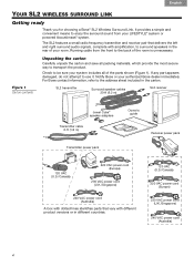
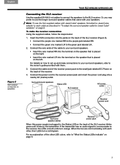
... first attach a Jewel Cube adapter to the transmitter. Or, you may prefer to the green jack labeled LR. 2. Connect the power cord to the SL2 receiver. English Dansk Deutsch Español Français Italiano Nederlands Svenska YOUR SL2 WIRELESS SURROUND LINK Figure 5 ... with them. 3. To make connections to your speakers. Surround sound speakers Status LED SL2 receiver AC power outlet Receiver power cord Surround speaker cables Receiver power pack When this power supply is placed on page 8. If the transmitter has no audio signal to communicate to the receiver,...
... first attach a Jewel Cube adapter to the transmitter. Or, you may prefer to the green jack labeled LR. 2. Connect the power cord to the SL2 receiver. English Dansk Deutsch Español Français Italiano Nederlands Svenska YOUR SL2 WIRELESS SURROUND LINK Figure 5 ... with them. 3. To make connections to your speakers. Surround sound speakers Status LED SL2 receiver AC power outlet Receiver power cord Surround speaker cables Receiver power pack When this power supply is placed on page 8. If the transmitter has no audio signal to communicate to the receiver,...
Operating guide
Page 27
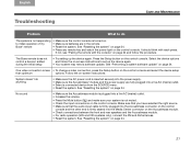
...6 TAB 7 TAB 8 CARE AND MAINTENANCE Problem What to do anything • Make sure the AC power cord is inserted securely into the power supply. • Make sure the Acoustimass® module and the power supply are in the remote. • Reset the system. It should blink with the console" on .... • Select a connected device from the SOURCE menu. • Reset the system. If not, see "Pairing the remote with each press. The Bose remote does not control a device I added during the initial setup • Try setting up the device again. • Your system may need a software...
...6 TAB 7 TAB 8 CARE AND MAINTENANCE Problem What to do anything • Make sure the AC power cord is inserted securely into the power supply. • Make sure the Acoustimass® module and the power supply are in the remote. • Reset the system. It should blink with the console" on .... • Select a connected device from the SOURCE menu. • Reset the system. If not, see "Pairing the remote with each press. The Bose remote does not control a device I added during the initial setup • Try setting up the device again. • Your system may need a software...
Installation guide
Page 3
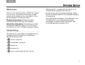
... setting up its contents before unpacking the next one. For Bose contact information, refer to the address sheet included in four numbered kits plus a small box containing the appropriate power cords: 1 • 1 Control console kit • 2 Acoustimass...Power cord kit (used with kits 1 and 2) TAB 5 TAB 6 TAB 7 TAB 8 SYSTEM SETUP Starting with Kit 1, unpack each kit and set up your home. Be sure to save all of your authorized Bose dealer immediately. Unpacking The parts of the packing materials. English TAB 2 TAB 3 TAB 4 Welcome Thank you for choosing a Bose® LIFESTYLE...
... setting up its contents before unpacking the next one. For Bose contact information, refer to the address sheet included in four numbered kits plus a small box containing the appropriate power cords: 1 • 1 Control console kit • 2 Acoustimass...Power cord kit (used with kits 1 and 2) TAB 5 TAB 6 TAB 7 TAB 8 SYSTEM SETUP Starting with Kit 1, unpack each kit and set up your home. Be sure to save all of your authorized Bose dealer immediately. Unpacking The parts of the packing materials. English TAB 2 TAB 3 TAB 4 Welcome Thank you for choosing a Bose® LIFESTYLE...
Installation guide
Page 4
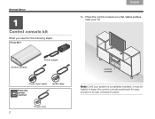
Control console Power supply Audio input cable From the power cord kit HDMI cable Power cord 2 Control console Note: Until your TV. TAB 8 TAB 7 SYSTEM SETUP TAB 6 11 Control console kit What you need for easy access to its rear connection panel. Place the control console on a flat, stable surface near your system is completely installed, it may be helpful to keep the control console positioned for the following steps: From Kit 1 TAB 5 TAB 4 TAB 3 TAB 2 English 1.
Control console Power supply Audio input cable From the power cord kit HDMI cable Power cord 2 Control console Note: Until your TV. TAB 8 TAB 7 SYSTEM SETUP TAB 6 11 Control console kit What you need for easy access to its rear connection panel. Place the control console on a flat, stable surface near your system is completely installed, it may be helpful to keep the control console positioned for the following steps: From Kit 1 TAB 5 TAB 4 TAB 3 TAB 2 English 1.
Installation guide
Page 6
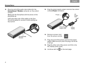
.... 8. Make sure you push the plug in as far as it while setting up . TAB 8 TAB 7 TAB 6 TAB 5 SYSTEM SETUP 4. Power AC power cord Power supply output cord Power supply 6. Plug the other end of the power cord into the Acoustimass® Module connector on the plug faces up the next kit. Make sure the flat surface with...
.... 8. Make sure you push the plug in as far as it while setting up . TAB 8 TAB 7 TAB 6 TAB 5 SYSTEM SETUP 4. Power AC power cord Power supply output cord Power supply 6. Plug the other end of the power cord into the Acoustimass® Module connector on the plug faces up the next kit. Make sure the flat surface with...

Installation guide
Page 7
Place the Acoustimass module on its side and locate the connector panel. Connector panel 5 Make sure there is a live AC outlet nearby. Acoustimass module Acoustimass module From the power cord kit Power cord 2. Lay the module on the floor at the same end of the room as the TV. English TAB 2 TAB 3 TAB 4 2 Acoustimass® module kit What you need for the following steps: From Kit 2 TAB 5 TAB 6 TAB 7 TAB 8 SYSTEM SETUP 1.
Place the Acoustimass module on its side and locate the connector panel. Connector panel 5 Make sure there is a live AC outlet nearby. Acoustimass module Acoustimass module From the power cord kit Power cord 2. Lay the module on the floor at the same end of the room as the TV. English TAB 2 TAB 3 TAB 4 2 Acoustimass® module kit What you need for the following steps: From Kit 2 TAB 5 TAB 6 TAB 7 TAB 8 SYSTEM SETUP 1.

Installation guide
Page 8
... Center TAB 4 TAB 3 TAB 2 English 4. Continue with the arrow faces the front of the power cord into a live AC (mains) power outlet. 7. Remove a power cord from the power cord kit. 5. Make sure the flat surface with Kit 3 on the Acoustimass module. Plug the other end of the module. TAB 8 TAB 7 SYSTEM SETUP ...TAB 6 TAB 5 CAUTION: DO NOT stand the Acoustimass® module on the Acoustimass module. Plug the free end of the power cord into the Media Center connector on its front or back end. 3. Plug one end of the audio input cable into the AC...
... Center TAB 4 TAB 3 TAB 2 English 4. Continue with the arrow faces the front of the power cord into a live AC (mains) power outlet. 7. Remove a power cord from the power cord kit. 5. Make sure the flat surface with Kit 3 on the Acoustimass module. Plug the other end of the module. TAB 8 TAB 7 SYSTEM SETUP ...TAB 6 TAB 5 CAUTION: DO NOT stand the Acoustimass® module on the Acoustimass module. Plug the free end of the power cord into the Media Center connector on its front or back end. 3. Plug one end of the audio input cable into the AC...


