The Bose® Lifestyle® amplifier - Owner's guide
Page 5
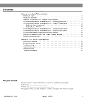
... remote control 10 Setting Zone 2 Protocol 10 Connecting the Lifestyle® stereo amplifier to a Model 20 music center 11 Connecting the Lifestyle® stereo amplifier to a Model 5 music center 13 Connecting speakers to your Lifestyle® stereo amplifier 14 Checking to see if you keep your Lifestyle® stereo amplifier. Contents Setting up your...
... remote control 10 Setting Zone 2 Protocol 10 Connecting the Lifestyle® stereo amplifier to a Model 20 music center 11 Connecting the Lifestyle® stereo amplifier to a Model 5 music center 13 Connecting speakers to your Lifestyle® stereo amplifier 14 Checking to see if you keep your Lifestyle® stereo amplifier. Contents Setting up your...
The Bose® Lifestyle® amplifier - Owner's guide
Page 9
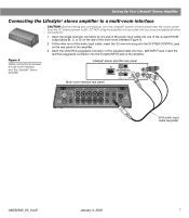
...; stereo amplifier to a multi-room interface CAUTION: Before making any connections, turn the Lifestyle® system off and disconnect the music center from the AC (mains) power outlet. DO NOT plug the amplifier into an outlet until you have ... INPUT 30-ft audio input cable (supplied) AM262840_00_V.pdf January 4, 2002 7 Figure 6 Cable connections between a multi-room interface and the Lifestyle® stereo amplifier Lifestyle® stereo amplifier rear panel Multi-room interface rear panel 4 Ω MINIMUM LL R L SYSTEM RR CONTROL L R +-
...; stereo amplifier to a multi-room interface CAUTION: Before making any connections, turn the Lifestyle® system off and disconnect the music center from the AC (mains) power outlet. DO NOT plug the amplifier into an outlet until you have ... INPUT 30-ft audio input cable (supplied) AM262840_00_V.pdf January 4, 2002 7 Figure 6 Cable connections between a multi-room interface and the Lifestyle® stereo amplifier Lifestyle® stereo amplifier rear panel Multi-room interface rear panel 4 Ω MINIMUM LL R L SYSTEM RR CONTROL L R +-
The Bose® Lifestyle® amplifier - Owner's guide
Page 10
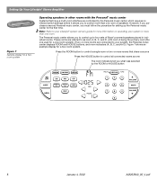
... you purchase a second Personal music center, you to control a single room or two or more than one room. If two or more than one room of Bose® powered speakers placed in individual rooms. These rooms are connected to four sets of speakers. Note: Refer to your Lifestyle® system owner's guide for...
... you purchase a second Personal music center, you to control a single room or two or more than one room. If two or more than one room of Bose® powered speakers placed in individual rooms. These rooms are connected to four sets of speakers. Note: Refer to your Lifestyle® system owner's guide for...
The Bose® Lifestyle® amplifier - Owner's guide
Page 13
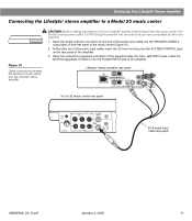
...of the amplifier. 3. Setting Up Your Lifestyle® Stereo Amplifier Connecting the Lifestyle® stereo amplifier to a Model 20 music center ® Figure 10 Cable connections between the Model 20 music center and the Lifestyle® stereo amplifier CAUTION: Before making ...connections, turn the Lifestyle® system off and disconnect the music center from the AC (mains) power ...
...of the amplifier. 3. Setting Up Your Lifestyle® Stereo Amplifier Connecting the Lifestyle® stereo amplifier to a Model 20 music center ® Figure 10 Cable connections between the Model 20 music center and the Lifestyle® stereo amplifier CAUTION: Before making ...connections, turn the Lifestyle® system off and disconnect the music center from the AC (mains) power ...

The Bose® Lifestyle® amplifier - Owner's guide
Page 14
... up a Zone 2 remote control Setting up the RC-20 remote control for Zone 2 If your system uses a Model 20 music center, you need to set up (on operating your system in your Lifestyle® system owner's guide for more than one room. Slide switch 5 down (off), and switches 6 and 8 up a second RC...
... up a Zone 2 remote control Setting up the RC-20 remote control for Zone 2 If your system uses a Model 20 music center, you need to set up (on operating your system in your Lifestyle® system owner's guide for more than one room. Slide switch 5 down (off), and switches 6 and 8 up a second RC...
The Bose® Lifestyle® amplifier - Owner's guide
Page 15
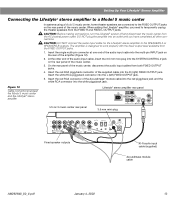
...the audio input cable into the SYSTEM CONTROL 2 jack on the rear of the music center. 3. Figure 12 Cable connections between the Model 5 music center and the Lifestyle® stereo amplifier Model 5 music center rear panel Lifestyle® stereo amplifier rear panel 4 Ω MINIMUM LL LL SYSTEM ...INPUT jack on the rear panel of the amplifier (Figure 12). 2. CAUTION: Before making connections, turn the Lifestyle® system off and disconnect the music center from the FIXED OUTPUT jacks. 1. The amplifier is designed to work properly with the fixed ...
...the audio input cable into the SYSTEM CONTROL 2 jack on the rear of the music center. 3. Figure 12 Cable connections between the Model 5 music center and the Lifestyle® stereo amplifier Model 5 music center rear panel Lifestyle® stereo amplifier rear panel 4 Ω MINIMUM LL LL SYSTEM ...INPUT jack on the rear panel of the amplifier (Figure 12). 2. CAUTION: Before making connections, turn the Lifestyle® system off and disconnect the music center from the FIXED OUTPUT jacks. 1. The amplifier is designed to work properly with the fixed ...
The Bose® Lifestyle® amplifier - Owner's guide
Page 16
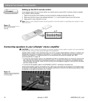
... cable to the SPEAKER OUTPUT L terminals in the listening area (as you need to set up a second RC-5 remote control to operate your Lifestyle® stereo amplifier. 1. Press the red terminal tab. Press the black terminal tab. Doing so may cause damage to any ampli&#...amplifier to powered speakers of two insulated wires. Setting Up Your Lifestyle® Stereo Amplifier ® Figure 13 RC-5 remote switch settings Setting up the RC-5 remote control If your system uses a Model 5 music center, you face it should always be connected to the SPEAKER OUTPUT R ...
... cable to the SPEAKER OUTPUT L terminals in the listening area (as you need to set up a second RC-5 remote control to operate your Lifestyle® stereo amplifier. 1. Press the red terminal tab. Press the black terminal tab. Doing so may cause damage to any ampli&#...amplifier to powered speakers of two insulated wires. Setting Up Your Lifestyle® Stereo Amplifier ® Figure 13 RC-5 remote switch settings Setting up the RC-5 remote control If your system uses a Model 5 music center, you face it should always be connected to the SPEAKER OUTPUT R ...
The Bose® Lifestyle® amplifier - Owner's guide
Page 17
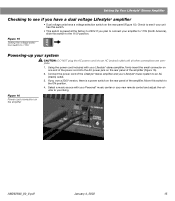
...amplifier and your Lifestyle® music system to your liking. Move this switch. • This switch is a power switch on the amplifier AM262840_00_V.pdf January 4, 2002 15 If you own a 230V version, there is preset at the factory to 230V. Select a music source with your new remote ...3. Figure 16 Power cord connection on the rear panel of the amplifier. Using the power cord included with your Personal® music center or your Lifestyle® stereo amplifier, firmly insert the small connector on one end of the power cord into an AC (mains) ...
...amplifier and your Lifestyle® music system to your liking. Move this switch. • This switch is a power switch on the amplifier AM262840_00_V.pdf January 4, 2002 15 If you own a 230V version, there is preset at the factory to 230V. Select a music source with your new remote ...3. Figure 16 Power cord connection on the rear panel of the amplifier. Using the power cord included with your Personal® music center or your Lifestyle® stereo amplifier, firmly insert the small connector on one end of the power cord into an AC (mains) ...

The Bose® Lifestyle® amplifier - Owner's guide
Page 18
...become dusty over time. Troubleshooting If you do Neither speaker plays • Make sure the Lifestyle® music center and the amplifier are in working order. • Be sure a music source is selected (AM, FM, CD, AUX, etc.). Problem What to arrange for ...guidelines below. For additional help, see the troubleshooting information in the product packaging for service, or contact Bose Customer Service. If the problem still exists, contact your Lifestyle® system after the wires are firmly connected at hardware stores. This is commonly available at...
...become dusty over time. Troubleshooting If you do Neither speaker plays • Make sure the Lifestyle® music center and the amplifier are in working order. • Be sure a music source is selected (AM, FM, CD, AUX, etc.). Problem What to arrange for ...guidelines below. For additional help, see the troubleshooting information in the product packaging for service, or contact Bose Customer Service. If the problem still exists, contact your Lifestyle® system after the wires are firmly connected at hardware stores. This is commonly available at...

Owner's guide
Page 2
... to alert the user to the presence of uninsulated dangerous voltage within an equilateral triangle, is located on the back panel and bottom of your Lifestyle® music center and the bottom panel of your Acoustimass® module: The lightning flash with a polarized power plug, to prevent electric shock, match wide blade...
... to alert the user to the presence of uninsulated dangerous voltage within an equilateral triangle, is located on the back panel and bottom of your Lifestyle® music center and the bottom panel of your Acoustimass® module: The lightning flash with a polarized power plug, to prevent electric shock, match wide blade...

Owner's guide
Page 5
... and the bottom panel of your Lifestyle® 25 system 28 Product Information Technical information 29 Accessories ...29 Index ...30 Bose® Corporation inside back cover AM187718_01_V.pdf For your Lifestyle® 25 system 15 The music center display 15 The system controls 16 Other music center controls 17 The Lifestyle® 25 remote control 17 Listening to compact...
... and the bottom panel of your Lifestyle® 25 system 28 Product Information Technical information 29 Accessories ...29 Index ...30 Bose® Corporation inside back cover AM187718_01_V.pdf For your Lifestyle® 25 system 15 The music center display 15 The system controls 16 Other music center controls 17 The Lifestyle® 25 remote control 17 Listening to compact...

Owner's guide
Page 6
... sent to reproduce the realism of movie sound especially for operating two listening zones Bose VideoStageTM decoder technology enables the Lifestyle® 25 system to left or right front speakers. Save your Lifestyle® 25 system, VideoStage directs sound so it to the surround (rear) speakers. This...; music center with built-in stereo, but not surround-encoded, VideoStage decoder technology directs it appears to come from the center of the TV screen. Sounds from all five speakers all of the time. You will help you for purchasing the Bose® Lifestyle® 25 system...
... sent to reproduce the realism of movie sound especially for operating two listening zones Bose VideoStageTM decoder technology enables the Lifestyle® 25 system to left or right front speakers. Save your Lifestyle® 25 system, VideoStage directs sound so it to the surround (rear) speakers. This...; music center with built-in stereo, but not surround-encoded, VideoStage decoder technology directs it appears to come from the center of the TV screen. Sounds from all five speakers all of the time. You will help you for purchasing the Bose® Lifestyle® 25 system...

Owner's guide
Page 7
...future use. Use care when you remove the protective plastic film from the bottom of the Lifestyle® music center before setting up your Lifestyle® 25 system: • Lifestyle® music center • Music center power pack* • 5 cube speaker arrays • 5 speaker cables (2 surround...Rubber feet Stereo cable Test CD AM antenna THE BOSE SPECIAL EDITION LIFESTYLE MUSIC SYSTEM CD ® Lifestyle® CD Australia AM187718_01_V.pdf December 20, 2001 5 Unpack the carton Carefully unpack your authorized Bose dealer immediately. Figure 1 What comes with your ...
...future use. Use care when you remove the protective plastic film from the bottom of the Lifestyle® music center before setting up your Lifestyle® 25 system: • Lifestyle® music center • Music center power pack* • 5 cube speaker arrays • 5 speaker cables (2 surround...Rubber feet Stereo cable Test CD AM antenna THE BOSE SPECIAL EDITION LIFESTYLE MUSIC SYSTEM CD ® Lifestyle® CD Australia AM187718_01_V.pdf December 20, 2001 5 Unpack the carton Carefully unpack your authorized Bose dealer immediately. Figure 1 What comes with your ...

Owner's guide
Page 9
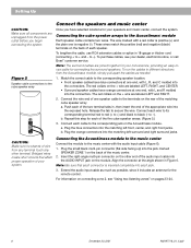
... port or creating too much bass. 6. An alternate position is at least 18 inches (45 cm) from the Acoustimass® module. Place the music center on the right side panel. 2. The rubber feet provide increased stability and protection from a wall and the ceiling. For proper ventilation, place... it within 30 feet (9.1 m) of the Acoustimass module (the length of your dealer or call Bose® customer service. 3. Note: Once you need additional audio and/or video cables to the same end of the sound source (Figure 3). Place ...
... port or creating too much bass. 6. An alternate position is at least 18 inches (45 cm) from the Acoustimass® module. Place the music center on the right side panel. 2. The rubber feet provide increased stability and protection from a wall and the ceiling. For proper ventilation, place... it within 30 feet (9.1 m) of the Acoustimass module (the length of your dealer or call Bose® customer service. 3. Note: Once you need additional audio and/or video cables to the same end of the sound source (Figure 3). Place ...
Owner's guide
Page 10
...into the connectors. to -). Note: The surround cables are joined together for your convenience, providing an easy-touse cable for your speakers and music center, connect the system. Release the tab to the Acoustimass® module Each speaker cable contains two wires. Repeat this step for the remote...the wire. These wires match the positive (red) and negative (black) terminals on the back of your dealer, electronics store, or call Bose® customer service. To lengthen the cable, use RCA extension cables or splice in Figure 6. Match the correct cable to the corresponding ...
...into the connectors. to -). Note: The surround cables are joined together for your convenience, providing an easy-touse cable for your speakers and music center, connect the system. Release the tab to the Acoustimass® module Each speaker cable contains two wires. Repeat this step for the remote...the wire. These wires match the positive (red) and negative (black) terminals on the back of your dealer, electronics store, or call Bose® customer service. To lengthen the cable, use RCA extension cables or splice in Figure 6. Match the correct cable to the corresponding ...

Owner's guide
Page 11
...power packs. Connecting the Acoustimass® module power cord 1. In Europe, use the correct power pack for your area. Connecting the music center power pack The Lifestyle® music center comes with either a 100V, 120V, 230V, or 240V power pack. If it to use the adapter plug provided. If you...setting. 2. Using the wrong one may damage your local electric utility for the proper voltage, slide it is not set correctly. Use only the Bose® power pack model specified for Europe and Australia. Use 115V for North America, and 230V for your area: • Model PS71, ...
...power packs. Connecting the Acoustimass® module power cord 1. In Europe, use the correct power pack for your area. Connecting the music center power pack The Lifestyle® music center comes with either a 100V, 120V, 230V, or 240V power pack. If it to use the adapter plug provided. If you...setting. 2. Using the wrong one may damage your local electric utility for the proper voltage, slide it is not set correctly. Use only the Bose® power pack model specified for Europe and Australia. Use 115V for North America, and 230V for your area: • Model PS71, ...

Owner's guide
Page 12
... electronics stores, or call Bose®customer service. Setting Up Figure 9 Connecting components through your TV If your stereo TV has fixed audio outputs (the audio signal level does not change), and it allows you must be supplied with the Lifestyle® 25 system. If your VCR...signal (VCR, laserdisc, cable, etc.): • Connect your TV, you set up your components. Note: Your Lifestyle® 25 system includes one 6-foot (1.8 m) stereo cable to the music center inputs. Match red connectors to right (R) jacks and black or white connectors to left (L) audio outputs from ...
... electronics stores, or call Bose®customer service. Setting Up Figure 9 Connecting components through your TV If your stereo TV has fixed audio outputs (the audio signal level does not change), and it allows you must be supplied with the Lifestyle® 25 system. If your VCR...signal (VCR, laserdisc, cable, etc.): • Connect your TV, you set up your components. Note: Your Lifestyle® 25 system includes one 6-foot (1.8 m) stereo cable to the music center inputs. Match red connectors to right (R) jacks and black or white connectors to left (L) audio outputs from ...

Owner's guide
Page 13
...Cable TV Laserdisc (3) To connect components directly to the Lifestyle® music center If you cannot (or do not choose to)... theater components to the appropriate VCR inputs. • Connect the VCR video out signal to the Lifestyle® music center. If the audio signal passes through two coaxial cable connections (like the connection from a cable...TV. Do not connect any speakers to the TV.) • Connect the VCR fixed audio outputs to your Lifestyle® system automatically selects SURROUND (5-speaker) mode, and selecting AUX or TAPE automatically selects STEREO (2-speaker) mode....
...Cable TV Laserdisc (3) To connect components directly to the Lifestyle® music center If you cannot (or do not choose to)... theater components to the appropriate VCR inputs. • Connect the VCR video out signal to the Lifestyle® music center. If the audio signal passes through two coaxial cable connections (like the connection from a cable...TV. Do not connect any speakers to the TV.) • Connect the VCR fixed audio outputs to your Lifestyle® system automatically selects SURROUND (5-speaker) mode, and selecting AUX or TAPE automatically selects STEREO (2-speaker) mode....

Owner's guide
Page 14
....pdf Connect the outputs (PLAY) from the component to your dealer for the appropriate model. Figure 13 Connecting other components to the music center AUX INPUT jacks. See Figure 13. Additional CD player or changer To use an external CD player or changer, connect the ... tape, or Digital Compact Cassette), connect the inputs (REC) of the tape deck to the music center TAPE IN jacks. Note: The Lifestyle® 25 system cannot turn a connected component on or off. Consult your Lifestyle® system, matching the red connector to R (right), white (or black) connector to connect...
....pdf Connect the outputs (PLAY) from the component to your dealer for the appropriate model. Figure 13 Connecting other components to the music center AUX INPUT jacks. See Figure 13. Additional CD player or changer To use an external CD player or changer, connect the ... tape, or Digital Compact Cassette), connect the inputs (REC) of the tape deck to the music center TAPE IN jacks. Note: The Lifestyle® 25 system cannot turn a connected component on or off. Consult your Lifestyle® system, matching the red connector to R (right), white (or black) connector to connect...

Owner's guide
Page 15
...Plug the FM antenna connector into the AM ANTENNA jack on a wall. To stand the antenna up on the back of your Lifestyle® music center provides connections for the supplied AM and FM antennas (Figure 14). Figure 14 The antenna connections Setting Up Connect the antennas ...installer. Note: A central antenna or cable, or an outdoor FM antenna, may want to adjust the antenna location or orientation as possible from the music center and other components, and at least four feet (1.2 m) from the Acoustimass® module. Follow all safety instructions. AM antenna connections 1. AM...
...Plug the FM antenna connector into the AM ANTENNA jack on a wall. To stand the antenna up on the back of your Lifestyle® music center provides connections for the supplied AM and FM antennas (Figure 14). Figure 14 The antenna connections Setting Up Connect the antennas ...installer. Note: A central antenna or cable, or an outdoor FM antenna, may want to adjust the antenna location or orientation as possible from the music center and other components, and at least four feet (1.2 m) from the Acoustimass® module. Follow all safety instructions. AM antenna connections 1. AM...


