Owner's guide
Page 9
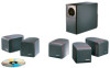
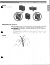
...to connect your system. There are already made for you . Figure 9 Separating cables //' age to your system. The connections at the Acoustimass module are three sets of cables, joined together to form ribbons, which can result in damage to your system. • The supplied... from the outlet (AC power mains). A CAUTION: Never use broken or frayed wiring which may result in electricalshock or dam- Figure 8 •oustimasc module positions Setting Up Your Acoustimass 600 Speaker System Connecting the speakers CAUTION: Before making any connections, turn off your receiver...
...to connect your system. There are already made for you . Figure 9 Separating cables //' age to your system. The connections at the Acoustimass module are three sets of cables, joined together to form ribbons, which can result in damage to your system. • The supplied... from the outlet (AC power mains). A CAUTION: Never use broken or frayed wiring which may result in electricalshock or dam- Figure 8 •oustimasc module positions Setting Up Your Acoustimass 600 Speaker System Connecting the speakers CAUTION: Before making any connections, turn off your receiver...

Owner's guide
Page 10
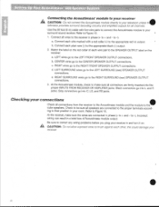
...extension cable available from Bose' Customer Service. A 8 e V a4 SURROUND MERCERS po*R con • I System input cable RS LS Surround speakers cable • 10 Refer to the outputs on the inside back cover. You may want to keep unextended lengths of wires to connect the Acoustimass module to page 18...center, left front, and right front cube speakers. • Use the 50 foot (15 m) surround speakers cable with two pairs of wires to connect the Acoustimass module to the left and right surround cube speakers. • Use the 20 foot (6 m) system input cable with five pairs of cable...
...extension cable available from Bose' Customer Service. A 8 e V a4 SURROUND MERCERS po*R con • I System input cable RS LS Surround speakers cable • 10 Refer to the outputs on the inside back cover. You may want to keep unextended lengths of wires to connect the Acoustimass module to page 18...center, left front, and right front cube speakers. • Use the 50 foot (15 m) surround speakers cable with two pairs of wires to connect the Acoustimass module to the left and right surround cube speakers. • Use the 20 foot (6 m) system input cable with five pairs of cable...
Owner's guide
Page 11
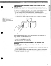
Setting Up Your Acoustimass 600 Speaker System • Connecting the Acoustimass® module to the center and front cube speakers A CAUTION: Never connect the cubes directly to the receiver. Use the 20 foot (6 m) cable with gray connectors to join the Acoustimass module to the surround speakers. • The... gray connector marked LS goes into the gray terminal on the left surround speaker (to your left of wires to connect the Acoustimass module to be sure the connectors are firmly inserted into the R jack. Figure 11 Inserting gray connector marked C into the...
Setting Up Your Acoustimass 600 Speaker System • Connecting the Acoustimass® module to the center and front cube speakers A CAUTION: Never connect the cubes directly to the receiver. Use the 20 foot (6 m) cable with gray connectors to join the Acoustimass module to the surround speakers. • The... gray connector marked LS goes into the gray terminal on the left surround speaker (to your left of wires to connect the Acoustimass module to be sure the connectors are firmly inserted into the R jack. Figure 11 Inserting gray connector marked C into the...
Owner's guide
Page 12
... 10. 1. television provides surround decoding circuitry and amplified outputs for all wires to the• cube speakers. a. b. At the Acoustimass module, check to make sure the wires are connected in a total loss of each plain wire (-) to the LEFT FRONT SPEAKER OUTPUT connections. Be sure to the ... in phase (+ to your receiver. • 12 A CAUTION: Do not allow exposed wires to brush against each wire marked with five wire pairs to connect the Acoustimass module to + and - LEFT wires go to the appropriate black (-) output. 2. At the receiver, make sure all connections ...
... 10. 1. television provides surround decoding circuitry and amplified outputs for all wires to the• cube speakers. a. b. At the Acoustimass module, check to make sure the wires are connected in a total loss of each plain wire (-) to the LEFT FRONT SPEAKER OUTPUT connections. Be sure to the ... in phase (+ to your receiver. • 12 A CAUTION: Do not allow exposed wires to brush against each wire marked with five wire pairs to connect the Acoustimass module to + and - LEFT wires go to the appropriate black (-) output. 2. At the receiver, make sure all connections ...
Owner's guide
Page 18
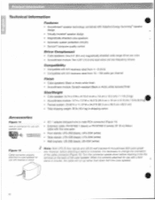
...wire-pairs • Floor stands: UFS-20B (black), UFS-20W (white) • Table stands: UTS-20B (black), UTS-20W (white) • Wall brackets: UB-20B (black), UB-20W (white) Figure 15 --- - 4P Note: Both UFS-20 floor stands and UB-20 wall brackets fit Acoustimass 600... cube speakers. 24' (' C. Sti Technical Information Features • • Acoustimass' speaker technology combined with Adaptive Energy Summingm speaker design • • Virtually Invisible• speaker design...
...wire-pairs • Floor stands: UFS-20B (black), UFS-20W (white) • Table stands: UTS-20B (black), UTS-20W (white) • Wall brackets: UB-20B (black), UB-20W (white) Figure 15 --- - 4P Note: Both UFS-20 floor stands and UB-20 wall brackets fit Acoustimass 600... cube speakers. 24' (' C. Sti Technical Information Features • • Acoustimass' speaker technology combined with Adaptive Energy Summingm speaker design • • Virtually Invisible• speaker design...


